Aiphone MEM Installation Manual and Operating Instructions
Open the original PDF document
View PDFMDM SERIES
Installation Manual and Operating Instructions
3 Channel - VOX -MOH - Phone and VoIP Interface
MD35M - 35 WATTS MD60M - 60 WATTS MD120M - 120 WATTS
IMPORTANT NOTE: THIS OPERATING MANUAL IS PROVIDED AS AN INSTALLATION AND AS AN OPERATING AID. MIEG CORPORATION and MEM AUDIO DOES NOT ASSUME ANY RESPONSIBILITY AS TO ITS ACCURACY AND SHALL NOT BE LIABLE IN TORT OR CON-TRACT FOR ANY DIRECT CONSEQUENTIAL OR INCIDENTAL LOSS OR DAMAGE ARISING FROM THE INSTALLATION, USE OR INABILITY TO USE THIS PRODUCT.
CAUTION !
TO REDUCE THE RISK OF FIRE OR ELECTRIC SHOCK DO NOT EXPOSE THIS APPLIANCE TO WATER, RAIN OR MOISTURE

SOUND IS BEAUTIFUL WWW.MEMAUDIO.COM
REV. 1.1

DESCRIPTION AND APPLICATIONS SPECIFICATIONS
3 Channel Inputs
Wide Frequency Response
Very Low Distortion
Balanced Microphone Input
Phantom Power on MIC Input with Selector
Balanced Telephone Paging Input
VoIP Telephone paging Input
Tel and Mic Vox Sensitivity Control
Auxiliary Input With Stereo Summing
Auxiliary Input Gain
Independent Input Controls
Bass and Treble Controls
VOX - Voice Activated Muting
Direct Muting or Unmuting
12 Volt Accessory Power Output
600 ohm or 10K (VoIP) MOH Output with Separate Output Level Control
8 ohm, 25 Volt & 70 Volt
Output Impedance
Rack Mounting with Optional Kits
Power Output: Distortion: 35/ 60/ 120 Watts RMS Less than 0.5% THD 20 - 20,000 Hz ± 2 db
Frequency Response:
Inputs:
Input 1 Auxiliary
Input 2 Microphone Balanced
Input 3 Telephone Transformer Balanced
Sensitivity & Z:
Input 1 Input 2* Input 3 Mic=1 Mv - 250 ohm balanced Tel=100 Mv - 600 ohm balanced Aux=200 Mv - 47K ohm
VoIP 50K ohm 100 Mv unbalanced
* Hum & Noise: Telephone Input: Music on Hold Output: Mic -70 db, Aux/ -75 db 600 ohm Transformer balanced 600 ohm-1 Volt Transf. balanced VoIP 10K - 1 Volt unbalanced
Output Impedance:
Controls:
Front Panel: AUX Volume, MIC Volume,
Rear Panel Telpage Volume, Bass, Treble AUX Input Gain, MOH Level
MIC/ TEL Vox Sensitivity On MIC Input w/internal jumper
8 ohm, 25 Volt and 70 Volt line
Phantom Power: MOH Source: AUX Input
Tone Control Action: +/-10 db at 100 Hz and 10 K hz
VOX:
Net Weight:
Voice Activated Muting MIC/TEL mutes AUX Input
External Contacts
Direct Muting: MIC Unmuting: Mutes or Unmutes MIC Input only
Rack Mounting: Power Requirement: Power Consumption: Optional Rack Kits 120 Volt, 50-60 Hz 110/ 230/ 600 VA
Terminations: Phoenix Connectors, RCA Jacks
Housing Finish: Black
Dimensions: 12.5"W., 8.5"D., 1.75"H.
10.95 Lbs
(5.0 Kg)
UNPACKING
Immediately upon receipt of the amplifier, inspect the unit and shipping container for indications of improper handling or in transit damage. The equipment was carefully inspected and tested before leaving the factory. Notify the Transportation Company immediately if any damage is found. ONLY THE CONSIGNEE CAN FILE A CLAIM WITH THE CARRIER FOR DAMAGE DURING SHIPMENT. Be sure to save the carton and packing material as evidence of damage for the shipper inspection. DO NOT SHIP the unit back to the factory unless authorized by the factory.
IN TRANSIT DAMAGES ARE NOT COVERED BY THE MEMWARRANTY.
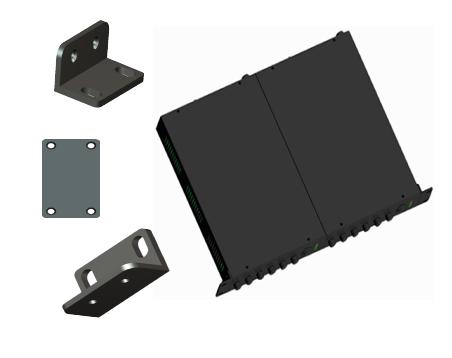
ACCESSORIES
(317.5x215.9x44.45mm)
MRK 1 - Standard 19" Rack Mounting Kit. Black finish. Complete with hardware
MRK 2 - Dual Amplifier 19" Rack Mounting Kit. Black finish. Complete with hardware
MRK1 Rack Kit

MRK2 Rack Kit


IMPORTANT SAFETY INSTRUCTIONS
READ BEFORE OPERATING READ BEFORE OPERATING
BEFORE OPERATING THE AMPLIFIER, BE SURE YOU FULLY UNDERSTAND ALL INSTRUCTIONS AND FEATURES OF THE APPLIANCE.
The lightning flash with arrowhead symbol, within an equilateral triangle, is intended to alert the user to the presence of uninsulated "dangerous voltage" within the product's enclosure that may be of sufficient magnitude to constitute a risk of electric shock to persons.
The exclamation point within an equilateral triangle is intended to alert the user to the presence of important operating and maintenance (servicing) instructions in the literature accompanying the appliance.
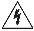


REFER SERVICING TO QUALIFIED SERVICE PERSONNEL. TO REDUCE THE RISK OF ELECTRIC SHOCK, DO NOT REMOVE COVER. NO USER-SERVICEABLE PARTS INSIDE. CAUTION:
CAUTION
- 1) Read these instructions carefully.
- 2) Keep these instructions.
- 3) Heed all Warnings.
- 4) Follow all instructions.
- 5) DO NOT use this apparatus near water.
- 6) Clean ONLY with a damp cloth.
- 7) DO NOT block any of the ventilation openings. Install in accordance with the instructions provided.
- 8) DO NOT install near any heat sources such as radiators, stoves, or other apparatus (including amplifiers) that produce heat.
- 9) DO NOT mount amplifier into a container or a closed unventilated closet while operating.
- 10) DO NOT place any object or accessory equipment such as Tuners, Mixers, Cassette Decks, etc. on top of the amplifier. Obstructing or closing the cabinet ventilation openings may cause overheating.
- 11) DO NOT defeat the safety purpose of the polarized or grounding type plug. A polarized plug has two blades with one wider than the other. A grounding type plug has two blades and a third grounding prong. The wide blade and or the third prong is provided for your safety. When the provided plug does not fit into your outlet, consult a certified electrician for replacement of the obsolete outlet.
- 12) Use only the attachments and accessories specified in this manual.

- 13) Do not place this product on an unstable cart, stand, tripod, bracket, or table. The product may fall, causing serious injury to a person, and serious damage to the product. If a cart is used, use caution when moving the cart/apparatus combination to avoid injury from tip-over.
- 14) Unplug this apparatus during lighting storms or when unused for long periods of time.
- 15) Refer all servicing to qualified service personnel only. Servicing is required when the apparatus has been damaged in any way, such as power supply cord or plug is damaged, liquid has been spilled or objects have fallen into the apparatus, the apparatus has been exposed to rain or moisture, does not operate normally, or has been dropped.
- 16) DO NOT replace fuses unless power cord is removed from the AC wall outlet.
- 17) DO NOT install accessories unless the power cord is removed from the AC wall outlet.
WARNING
WARNING:TO REDUCE THE RISK OF FIRE OR ELECTRIC SHOCK, DO NOT EXPOSE THIS APPLIANCE TO RAIN OR MOISTURE. DAN-GEROUS HIGH VOLTAGES ARE PRESENT INSIDE THE ENCLOSURE. DO NOT OPEN THE CABINET. REFER SERVICING TO QUALIFIED PERSONNEL ONLY.

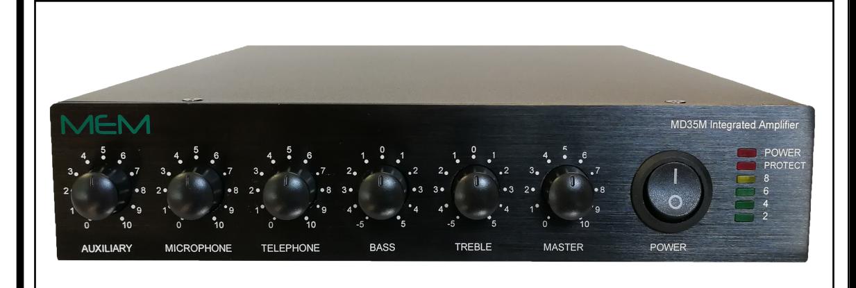
INTEGRATED AMPLIFIERS

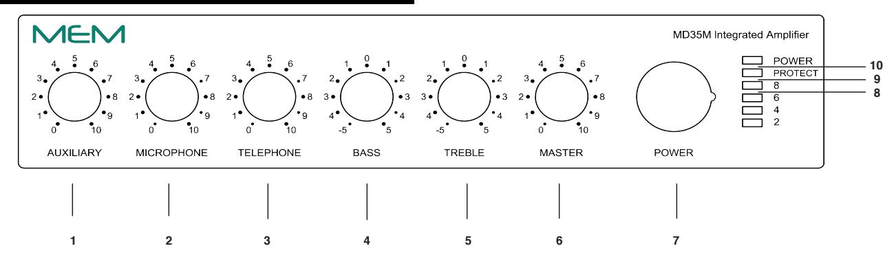
FRONT PANEL CONTROLS
Fig. 4 - Front Panel Controls
7)
- AUXILIARY Volume Control 1)
- 2) MICROPHONE Volume Control
- 3) TELEPHONE Volume Control
- 4) BASS Control
-
TREBLE Control
5) 6)
- MASTER Volume Control 9)
- POWER Switch
- POWER Indicator 10)
-
8) SIGNAL LEVEL Indicator
- PROTECT Indicator
Fig. 4A - Rear Panel Inputs and Outputs REAR PANEL INPUTS OUTPUTS
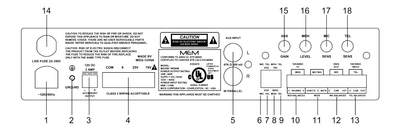
- AC Power Cord
- Chassis Ground Screw 2)
- 3) 12 Volt Accessory Power Tap
- Speaker Output 4)
- 5) AUX Input
- Mic Vox Circuit Off/On 6)
- Tel Vox Circuit Off/On 7)
- MOH 10K/600 Ohm (VoIP) 8)
- 9) Tel Input 10K/600 Ohm (VoIP)
- MOH Balanced Output 10)
- Unmute/ Mute Terminal 11)
- 12) Microphone Balanced Input
- Telephone Balanced Input 13)
- AC Line Fuse 14)
- AUX Input Gain 15)
- 16) MOH Output Level
- 17) MIC Vox Sensitivity
- 18) TEL Vox Sensitivity
RACK MOUNTING
- A) Procure the optional accessory MRK1 Rack Mount Kit. Fig. 4B Optional MRK2 side by side kit.
- B) Turn amplifier up side down and remove the four rubber feet by removing the four center pins.
- C) Remove three screws on each side of the amplifier holding the amplifier cover.
D) Install the rack kit brackets by using the self-tapping screws provided.
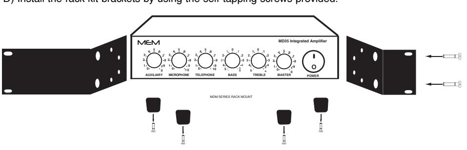
Fig. 4B - MRK2 SXS Rack Kit Mounting

INSTALLATION AND WIRING
CAUTION ! REMOVAL OF THE AMPLIFIER COVER PRESENTS AN ELECTRICAL SHOCK HAZARD ALWAYS REMOVE THE POWER CORD FROM THE AC WALL OUTLET
THE SERVICING INSTRUCTIONS ARE FOR USE BY QUALIFIED PERSONNEL ONLY.TO AVOID ELECTRIC SHOCK DO NOT PERFORM ANY SERVICING OTHER THAN THAT CONTAINED IN THE OPERATING INSTRUCTIONS UNLESS YOU ARE QUALIFIED TO DO SO. REFER SERVICING TO QUALIFIED SERVICE PERSONNEL ONLY.
TROUBLESHOOTING CHART
This Troubleshooting Chart is provided to the installer as an aid in locating and correcting possible problems that may arise during installation or after use. This chart should only be used by qualified personnel trained in repair and maintenance of electrical apparatus.
PROBLEM SYMPTOMS PROBABLE CAUSE
AMPLIFIER IS COMPLETELY DEAD.
POWER INDICATOR DOES NOT GLOW.
POWER INDICATOR GLOWS BUT THERE IS NO OUTPUT FROM THE AMPLIFIER.
LOUD HUM OR CRACKLING SOUND FROM THE SPEAK-ERS.
OUTPUT LEVEL CHANGES CYCLICALLY
SOUND IS INTERMITTENT.
SOUND IS DISTORTED AND OVERDRIVEN.
ACOUSTIC FEEDBACK OR LOUD SQUEAL OCCURS WHEN AMPLIFIER IS TURNED ON.
- 1) NO VOLTAGE PRESENT AT AC OUTLET.
- 2) AC LINE FUSE OPEN.
- 3) DEFECTIVE OR OPEN POWER CORD.
- 4) POWER SWITCH INOPERATIVE.
- 5) POWER TRANSFORMER WINDING OPEN.
- 6) POWER INDICATOR DEFECTIVE OR DISCONNECTED.
- 1) INPUT CONTROLS SETTING NOT ADJUSTED PROPERLY.
- 2) SPEAKER WIRES SHORTED.
- 3) SPEAKER(S) LINE INTERRUPTED.
- 4) MICROPHONE OR PROGRAM SOURCE INTERRUPTED.
- 1) MICROPHONE INPUTS INCORRECTLY WIRED.
- 2) OPEN GROUND OR SHIELD IN INPUT CABLES.
- 3) SPEAKER TERMINALS SHORTED TO CHASSIS GROUND.
- 1) SPEAKER LINE SHORTED.
- 2) ONE OR MORE SPEAKER OR LINE TRANSFORMER SHORTED.
- 3) OUTPUT IMPEDANCE LOAD MISMATCHED WITH AMPLIFIER OUTPUT IMPEDANCE SETTING (OVERLOAD).
- 4) IN CONSTANT VOLTAGE SYSTEMS (25-70 V) THE TOTAL LOAD POWER REQUIREMENT EXCEEDS THE AMPLIFIER POWER RAT-ING (OVERLOAD).
- 5) EXCESSIVELY HIGH SETTING OF ONE OR MOREVOLUME CON-TROLS.
- 1) MICROPHONE IS LOCATED TOO CLOSE OR IS FACING SPEAK-ERS.
- 2) VOLUME CONTROL SETTING TOO HIGH.
- 3) TONE CONTROLS SHOULD BE SET IN THE CUT RANGE.
AC LINE FUSE REPLACEMENT
CAUTION: TO REDUCE THE RISK OF FIRE REPLACE ONLY WITH THE SAME TYPE OF FUSE.
Procure a Fuse Type: GMA UL
Turn amplifier power switch to the Off position. Remove power cord from AC outlet. Insert the tip of a cross screwdriver inside the Fuse Holder Cross screw, turn screw counterclockwise and remove the fuse by pulling outwardly. Replace Fuse in fuse holder.

CUSTOMER SERVICE
REPLACEMENT PARTS
Please provide complete information when you request replacement parts from either the Factory or a MEM Authorized Distributor. Be certain to include the Part Number and Description as it appears on the parts list, the Model Number of the unit and if possible the Serial Number and the date of purchase of the unit. Replacement parts inventory is maintained specifically to repair MEM products. Part sales for other reasons or applications will be declined.
ORDERING FROM THE FACTORY Print all information on a purchase order form and mail to: 2300 CLEMENTS FERRY ROAD, SUITE 202 CHARLESTON, SC 29492 MIEG CORPORATION
Be sure to include the following:
- MEM part number
- Part description
- Quantity required
- Model number of the unit
- Serial number of the unit
- Your payment or your authorization for COD shipment for parts not covered by the Warranty or if your company has a current account with the factory
RETAIN ORIGINAL IN WARRANTY PARTS UNTIL YOU RECEIVE REPLACEMENTS. PARTS THAT SHOULD BE RETURNED TO THE FACTORY WILL BE LISTED ON YOUR PACKING SLIP.
For your convenience replacement parts are also available through MEM Authorized Distributors and Dealers nation wide. Obtain a location list directly from the Factory or your regional MEM Representative.
TECHNICAL CONSULTATION
- Need help with your installation ?
- Need help with the operation of the unit ?
- Need help with a repair ?
Call or write for assistance. You will find our Technical Dept.. eager to help or assist you with any technical problem you may have encountered except "`Customizing'' for a unique application.
The effectiveness of our consultation service depends on the accuracy of the information you furnish. Be sure to tell us:
- The Model and Serial number of the unit
- The date of purchase
- An exact description of the problem
- All you have done in attempting to correct the problem
Call our Customer Service phone number:
1-843-819-8883
REPLACEMENT PARTS REPAIR SERVICE
REPAIR SERVICE
Repair service for out of warranty MEM products may be obtained form your local MEM distributor or any other qualified repair station.
In warranty repairs must be returned to the Factory. Prior authorization must be obtained from the Factory. Products received without authorization will be refused by our Receiving Department.
IN WARRANTY REPAIR SERVICE
Call or write the Factory to obtain an authorization to return the product for repairs.
Pack the equipment in the original carton or in a strong carton with at least THREE INCHES of resilient packing material on all sides, top and bottom. Seal the carton with reinforced tape and mark it FRAGILE on at least two sides. Remember, the Carrier will not accept liability for shipping damages if the unit is improperly packed.
EQUIPMENT RECEIVED IN DAMAGED CONDITION DUE TO POOR PACKING WILL BE REFUSED AND THE WARRANTY COVERAGE IS AUTOMATICALLY VOIDED.
The MEM Limited Warranty provides:
The examination of the returned product must disclose in our judgement, a manufacturing defect. The warranty does not extend to any product that has been subject to misuse, neglect, accident, improper installation or where the serial number of the product has been removed or defaced.
Ship via insured prepaid via UPS, FedEx, DHL or USPS to:
2300 CLEMENTS FERRY ROAD, SUITE 202 CHARLESTON, SC 29492 ATTN.: SERVICE DEPARTMENT The equipment will be returned freight prepaid after repairs. MIEG CORPORATION
Be sure to include the following:
- Your name and address
- Date of purchase and copy of invoice
- A brief description of the problem
- A return address shipping label
OUT OF WARRANTY REPAIR SERVICE
Follow return instructions as per in warranty repair service. Prior to performing all necessary repairs, you will be advised of the charges and at that time a written authorization by you will be required including authorization to return the equipment COD for the service and shipping charges. This will avoid unnecessary delays in returning the equipment to you.