Aiphone IX System QuickStart Programming Guide 1
Open the original PDF document
View PDFAIPHONE
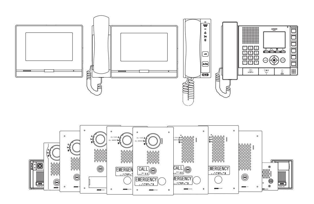
IX SYSTEM
IP Network-Compatible System
Quick Start Programming Guide
IX Support Tool version 5.0.0.0 or later
ATTENTION:
This is an abbreviated programming manual addressing basic program settings for an IX System using the IX Support Tool. A complete set of instructions (IX Web Setting Manual / IX Operation Manual / IX Support Tool Setting Manual) can be found at www.aiphone.net. In North America for additional literature and media, visit www.aiphone.com/IX.
GENERAL OVERVIEW:
Table of Contents
| Pages 3-7 | Programming a New System |
|---|---|
| - Create a New System Using the Support Tool Programming Wizard | |
| Page 8-10 | Network Camera Integration |
| - Adding a 3rd Party IP Camera | |
| Page 11-13 | SIP Server and VoIP Phone Integration |
| - Adding a VoIP phone and SIP server | |
| Page 14-16 | Partitioning a System |
| - Master Station Address Book and Door Station Call-in | |
| Page 17-20 | Call Transfer |
| - Setting up Absent, Delayed, and Scheduled Transfers | |
| Page 21-24 | Adding a New Station |
| - Adding and Configuring a new IX Station |
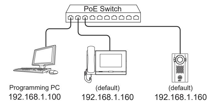
System Preparation
Support Tool has been downloaded and installed The programming PC and the IX Series stations have been connected to a PoE switch (not router) and have completed their boot up process. The programming PC is in the same subnet (default 192.168.1.x) as the IX Series stations. Before beginning the programming process, ensure the following steps have been completed:
Network Information and Installation Requirements
IX Series stations are set to the same default IPv4 address of 192.168.1.160 . The Support Tool programming software is designed to batch configure all IX stations simultaneously, finding each device on the network via its individualized MAC address. Note that the IX Series is designed to function on a managed network, but the broadcast protocol used to find IX stations may not function properly in this environment.
It is possible that a secondary NIC card, such as a VPN or WiFi connection, may prevent Support Tool from finding stations on a network during programming, including the association and uploading processes. Disabling these network interface cards before programming may prevent these issues.


For best results, place all IX stations on the same unmanaged network switch and wait for each station to power on before launching Support Tool.
System functionality when using programming Wizard
The Support Tool Programming Wizard is designed to quickly configure IX Series stations, automating the programming steps needed to configure a basic system. This configuration gives each station a default Station Name, Number, and IP address, as well as enables door release. Additional settings are available once the programming has been completed using the wizard.
Note: Support Tool can be downloaded from www.aiphone.net
Getting Started
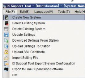
To create a New System using the Programming Wizard, launch Support Tool and enter the ID (Username) and Password. If this is the first time Support Tool is launched, the New System programming window will automatically open. However, if an existing program file is currently in use, choose File(F) > Create New System.
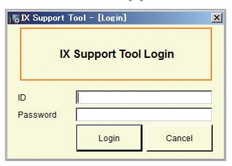
Default Settings
ID: admin Password: admin
Launch IX Support Tool Select Create New System
Step 1: System Settings
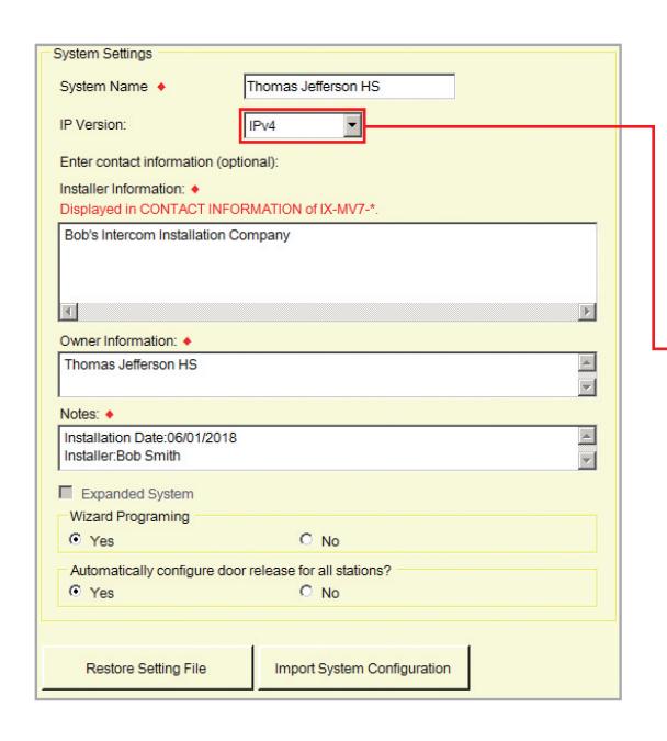
1.1 - System Settings
Fill in all fields.
System Name, Installer Information, Owner Information, and Notes are all customizable fields that uniquely identify information about the system being created.
Protocol
IPv4 is the default. If using IPv6, select it from the drop down menu.
*This Guide will explain network and system settings using IPv4 examples.
1.2-Wizard Programing
Confirm that Yes is selected.
1.3-Door Release Setting
Select Yes to automatically configure door release for all stations.
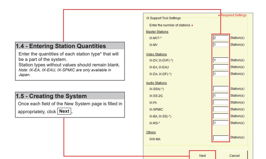
* Station Type Key
IX-MV7-*:
IX-MV7-HB, IX-MV7-HW, IX-MV7-B, IX-MV7-W
IX-DV, IX-DVF(-*):
IX-DVF-P, IX-DVF-2RA, IX-DVF-RA
IX-DA, IX-DF(-*):
IX-DF-HID, IX-DF-RP10, IX-DF-2RA
IX-SSA(-*):
IX-SSA-2RA, IX-SSA-RA
IX-BA, IX-SS(-*):
IX-SS-2RA, IX-SS-RA
IX-RS-*:
IX-RS-B, IX-RS-W
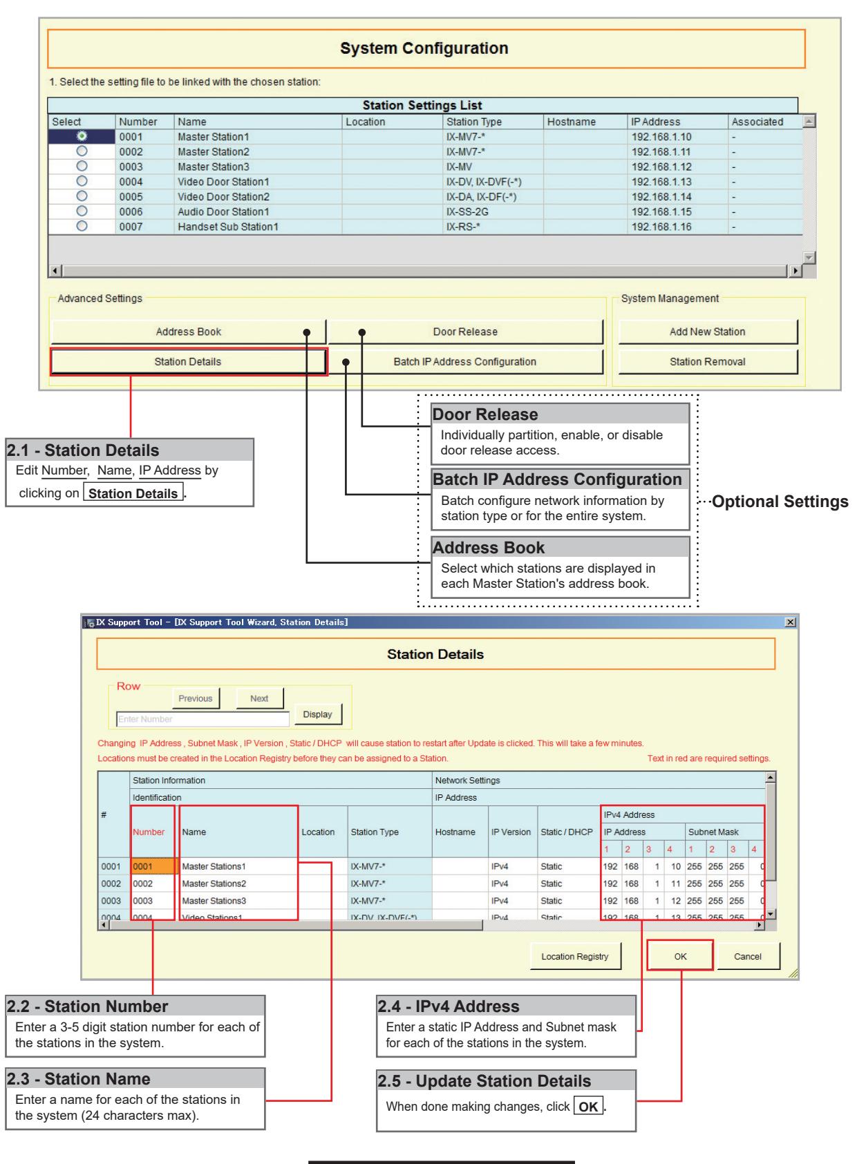
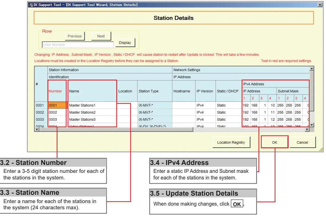
Step 2: Station Customization - Optional
Support Tool will provide each station a default Station Name, four-digit Number, and IP Address starting from 192.168.1.10. To edit this information, click Station Details in the Advanced Settings section, shown below. To use the default information created by Support Tool, skip to Step 3.
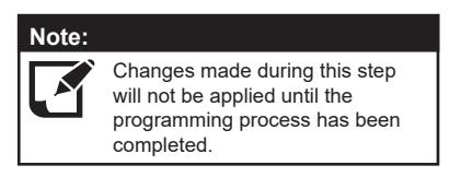
Step 3: Association
The association process is where the station information created in Support Tool is associated with a station found on the network. Choose one of two methods, Automatic (recommended) or Manual (page 6). Once associated, the station will receive its Station Name, Number, and network information after a short power cycle.
Automatic
Clicking the <u>Associate Automatically</u> button will pair a station from the top <u>Station Settings List</u> to the same type of station in the <u>Station List</u> below it. The stations are chosen at random. When the stations have been associated, scroll to the bottom of this page to review the <u>Associated Station List</u>, and confirm each station's status. This list will show each station's newly associated information, as well as it's MAC address. This is the recommended association method for stations in a bench scenario.
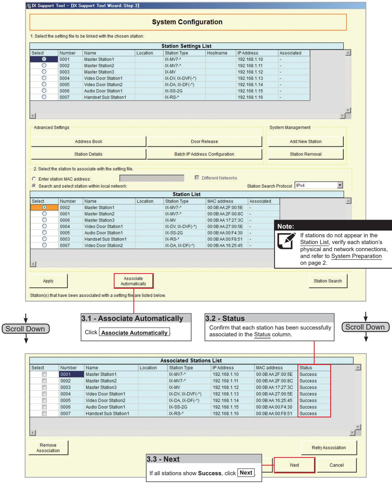
Go to page 7 "Setting File Upload"
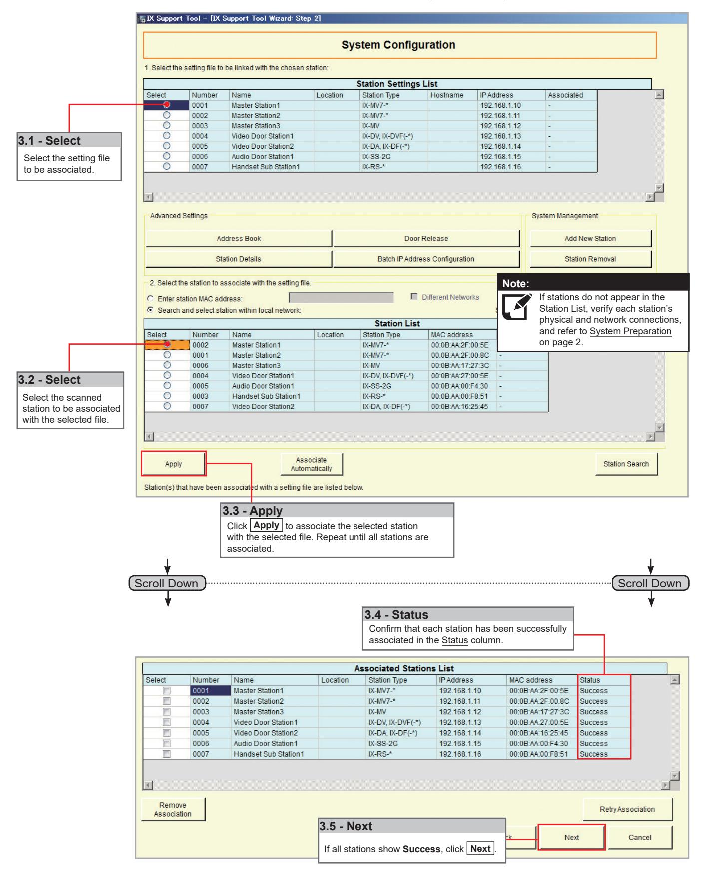
Step 3: Association
Manual
Manual Association allows the selection of a station by MAC address to pair with a station of the same type from the top Station Setting List and the Station List below it. When the stations have been associated, scroll to the bottom of this page to review the Associated Station List, and confirm each station's status. This is the recommended association method for stations that have already been deployed.
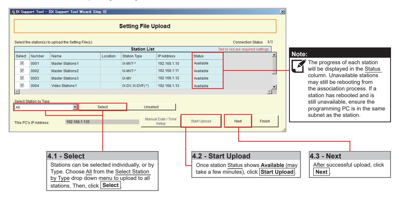
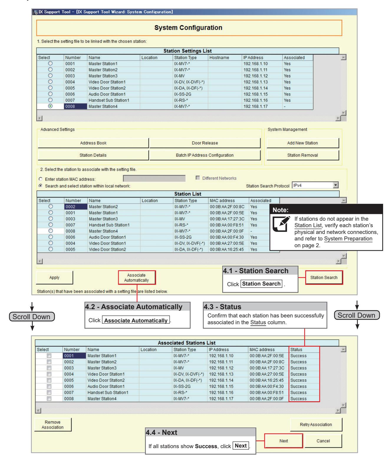
Step 4: Setting File Upload
Once each station has been associated with its individual station information, the setting file containing the rest of the system's information will need to be uploaded to each station. To upload the setting file, the programming PC will need to be in the same subnet as the associated stations (refer to Step 3). The PC's current IP address is listed in the bottom left-hand side of this window.
Note that without uploading a setting file, most functions and features will be unavailable to the stations.
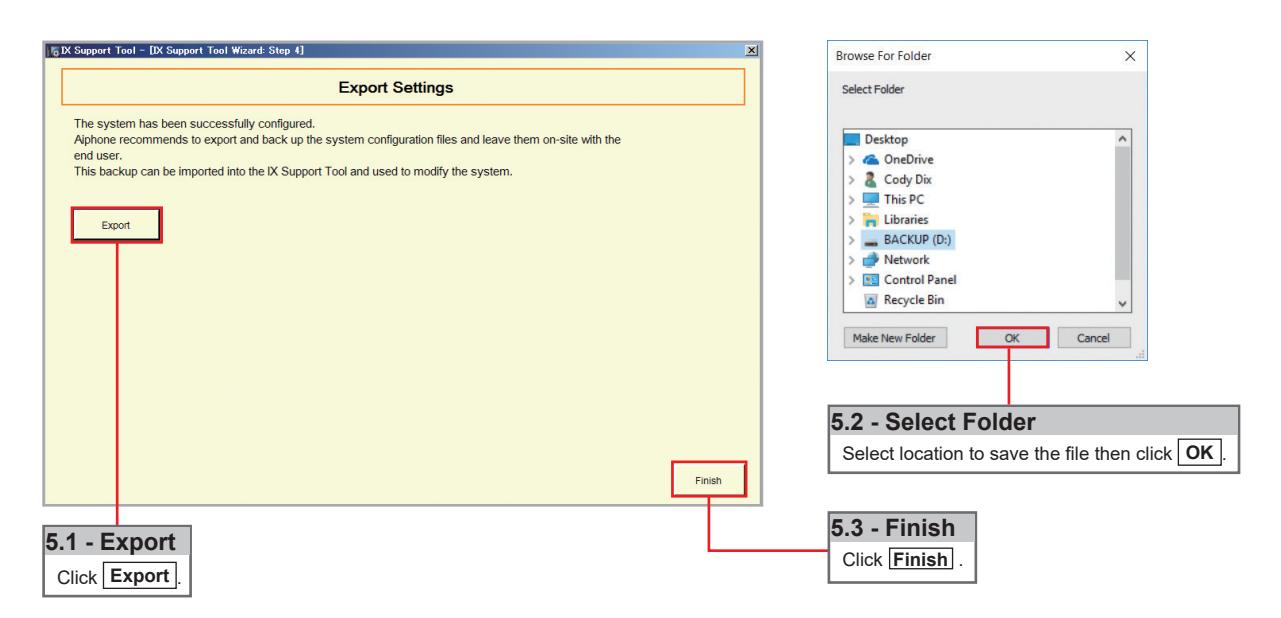
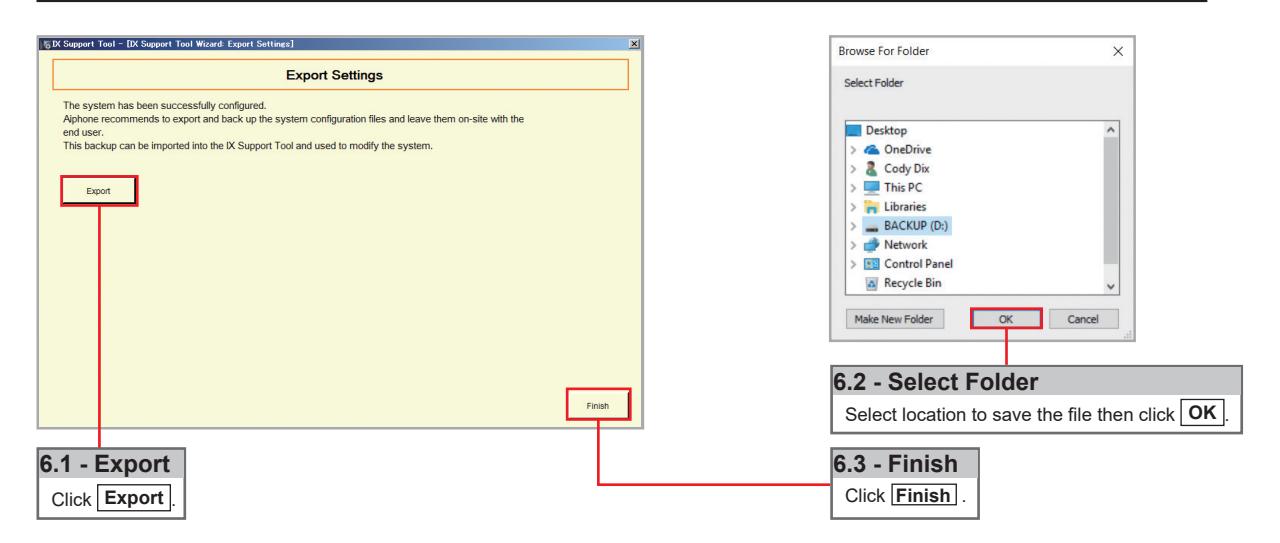
Step 5: Export Settings
The final step in the Programming Wizard is to create a copy of the system's setting file and export it to a secure location or external drive.

Network Camera Integration
Getting Started
The IX Series allows integration of network cameras that are ONVIF profile S compliant. These cameras can be called up by either audio or audio and video stations, as well as individually monitored by master stations.
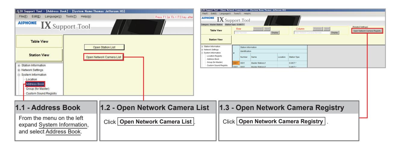
Step 1: Opening Network Camera Registry
Network Cameras must be registered in Support Tool prior to associating with a station.
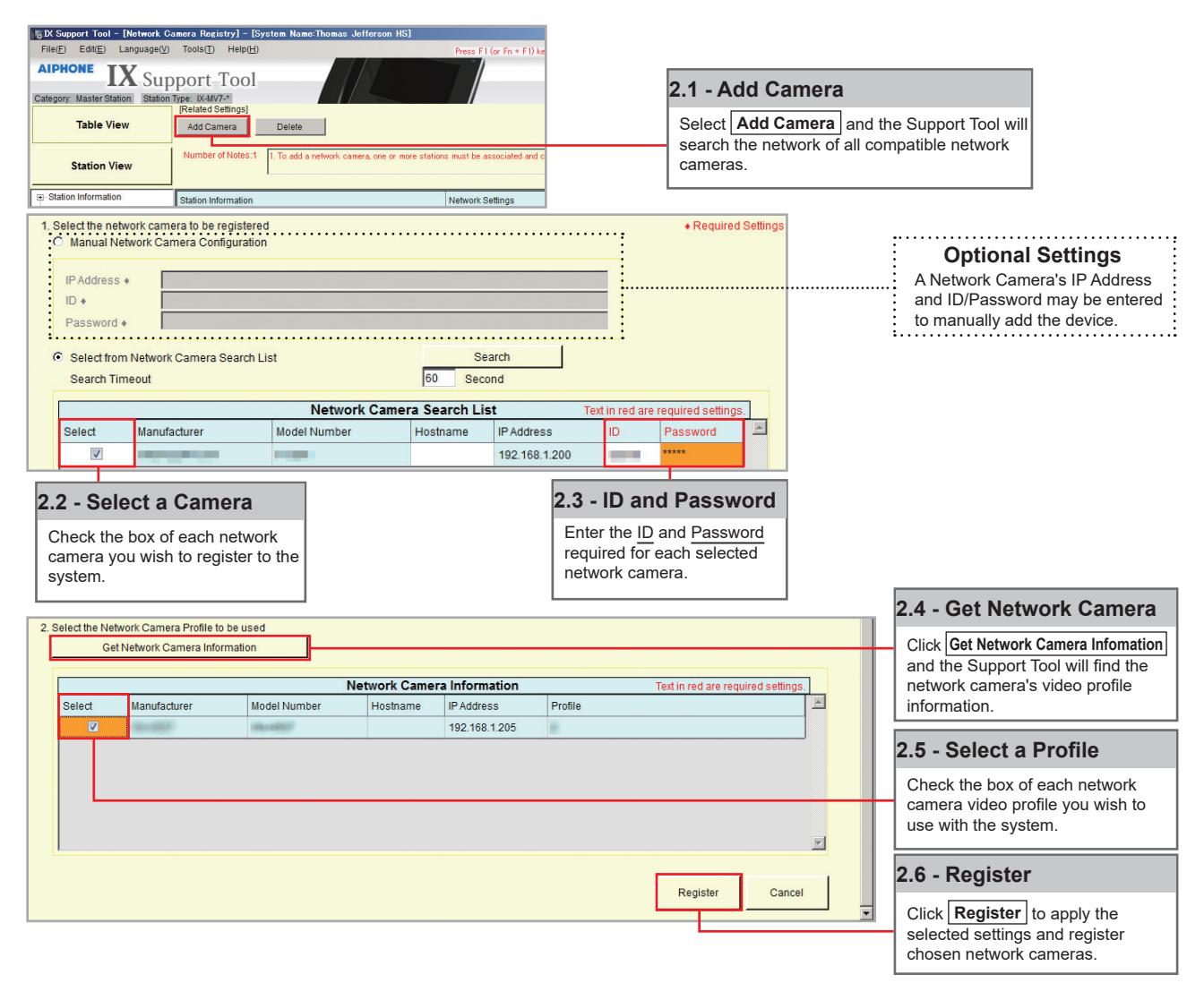
Step 2: Registering a Network Camera
Support Tool will search for available Network Cameras on the network, and any camera found will be listed in the Network Camera Search List. If a known camera is not found, place the programming PC on the same network switch as the camera(s), and attempt the search again.
Network Camera Integration
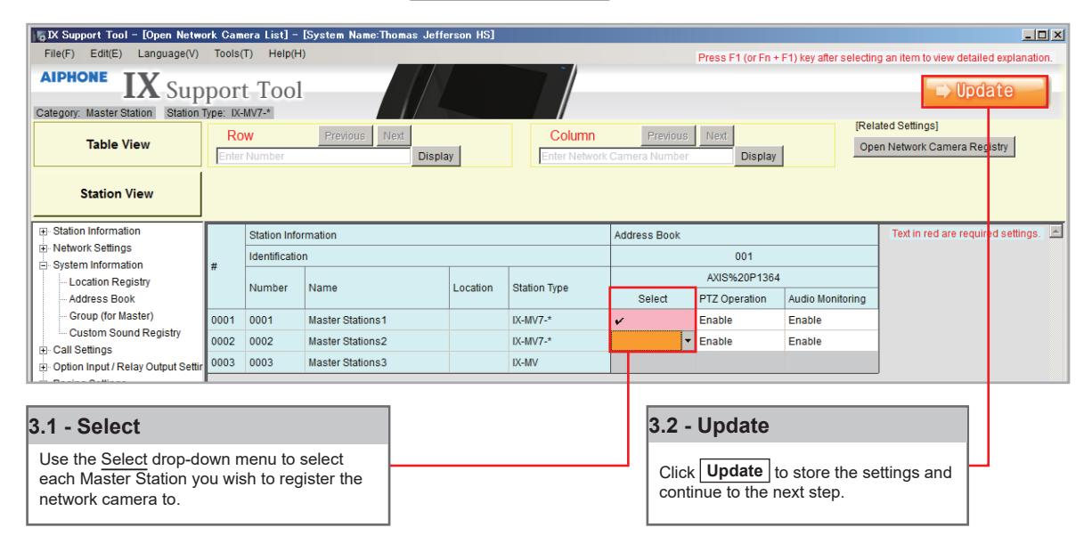
Step 3: Registering a Network Camera to a Master Station
For a Master Station to interact with a Network Camera, either during a camera call-up or while monitoring, it must be registered to a Master Station's Network Camera List.
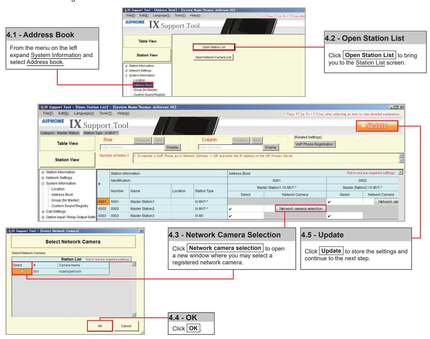
Step 4: Assigning a Network Camera to a Station
To allow a Network Camera to be used in conjunction with an IX Series station for camera call-up, the camera must be registered to each station it will interact with.
Network Camera Integration
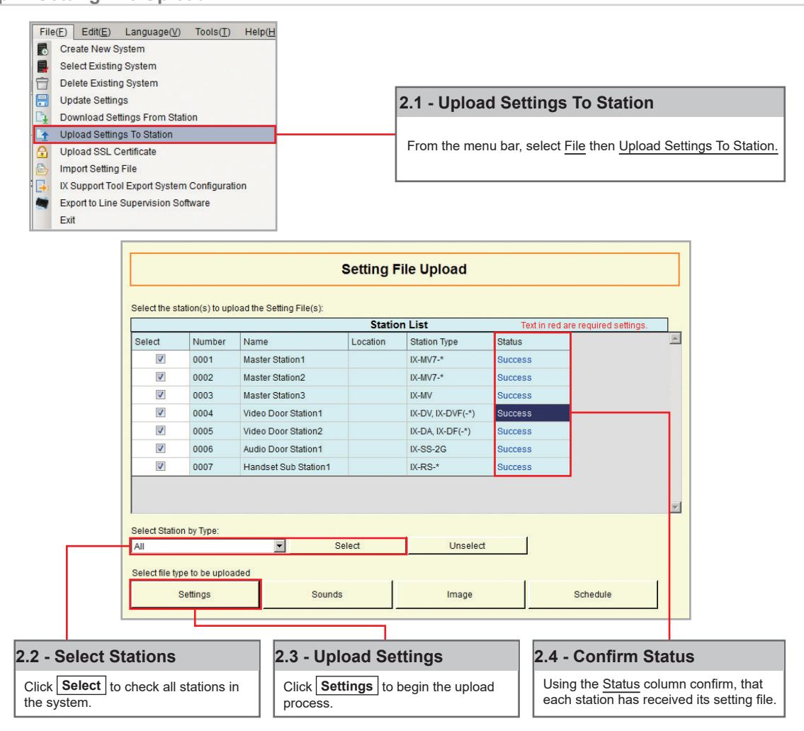
Step 5: Setting File Upload
The final step in this process is uploading the setting file to each station. This program file contains the Network Camera information, as well as the Network Camera settings configured for each station.
Note that without uploading a setting file, most functions and features will be unavailable to the stations.
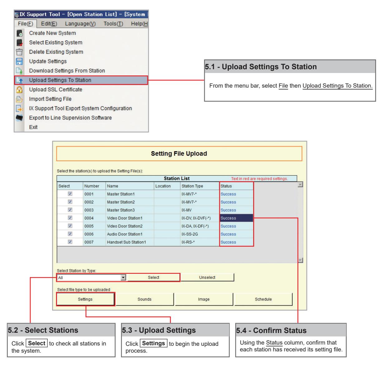

It is recommended that a copy of the settings be saved after uploading settings to the stations. Refer t o page 7 o f this guide for the procedure to export and save settings.
SIP Server and VoIP Phone Integration
Getting Started
For SIP server and VoIP phone integration, configuration is needed both within the SIP Server as well as Support Tool. IX Series stations must be registered within the SIP server and given an extension, and the SIP server information must also be added to Support Tool. SIP server configuration varies by manufacturer. Refer to the manufacturer's literature for more information or support.
SIP Server Registration
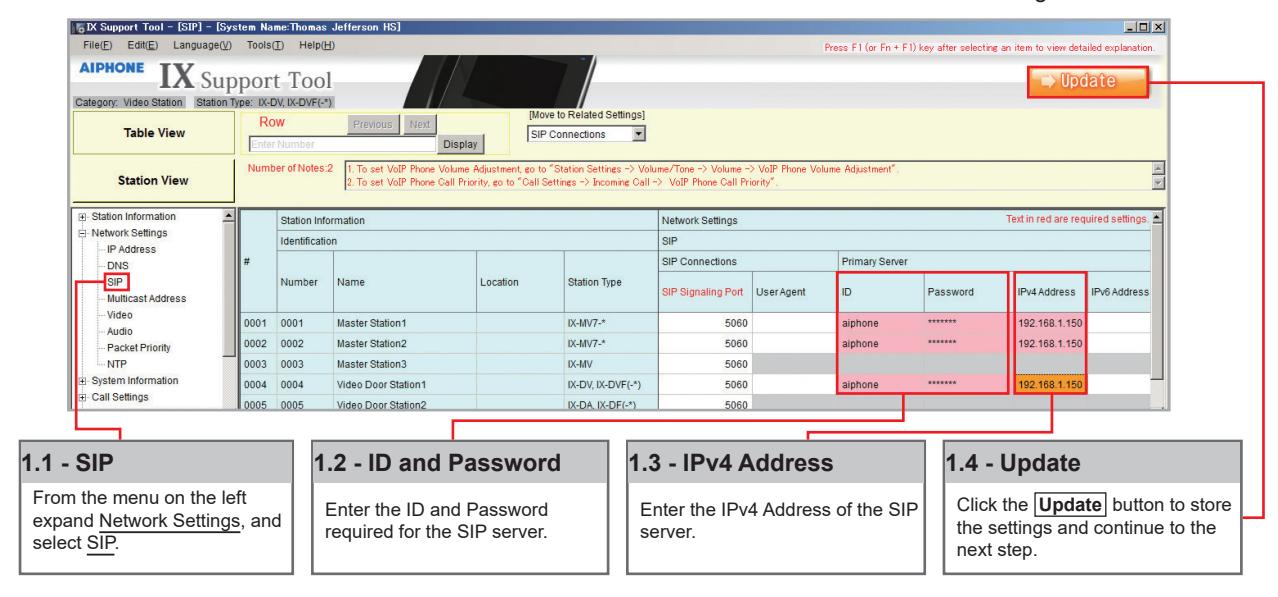
Step 1: SIP Server Registration
Enter the network information and ID/Password for the SIP server the IX Series station is registered to.
Step 2: Setting File Upload
SIP Server and VoIP Phone Integration
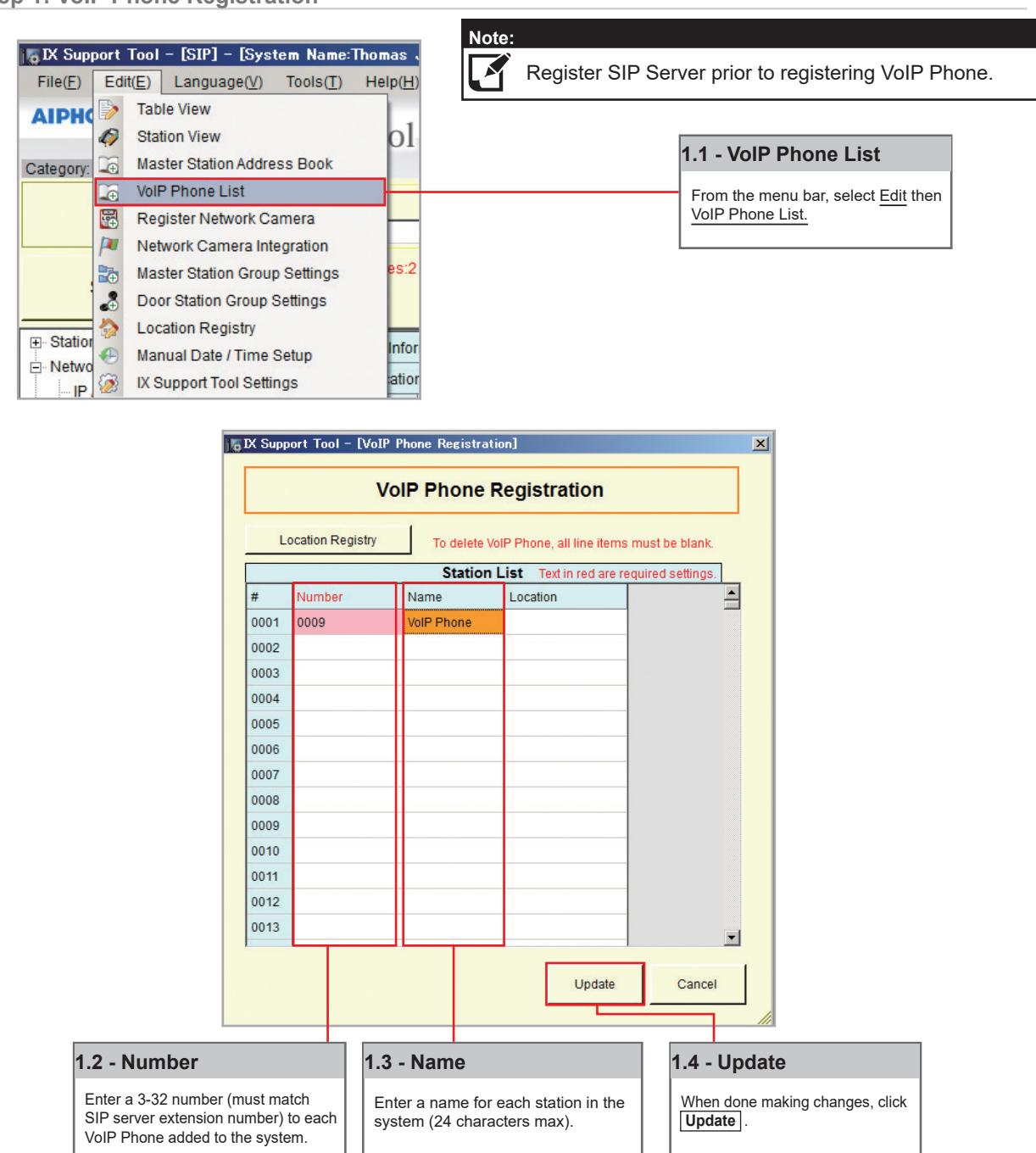
VoIP Phone Registration
Step 1: VoIP Phone Registration
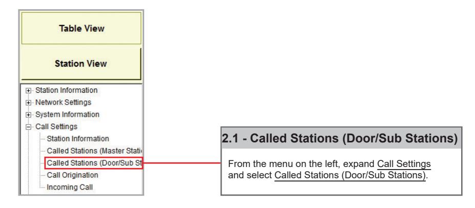
Step 2: Door Station Call List
Enabling a door station to call a registered VoIP phone.
SIP Server and VoIP Phone Integration
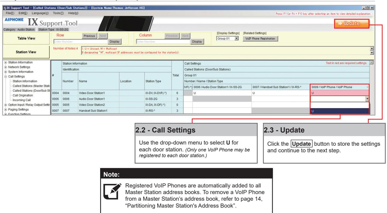
Step 2: Door Station Call List (cont.)
Step 3: Setting File Upload

It is recommended that a copy of the settings be saved after uploading settings to the stations. Refer to page 7 of this guide for the procedure to export and save settings.
Partitioning a System
Getting Started
An IX Series system can be partitioned into smaller groups of stations within a single system by editing Master Station Address Books, as well as individual Door Station call groups.
Master Station
Step 1: Address Book
Each Master Station has an address book that, by default, contains the station information for every station that is part of the system. A station must exist in a Master Station's address book if the Master Station should be able to call that station directly, activate a Door Station's door release, transfer a call to another Master Station, or any other feature requiring interaction by the Master Station.
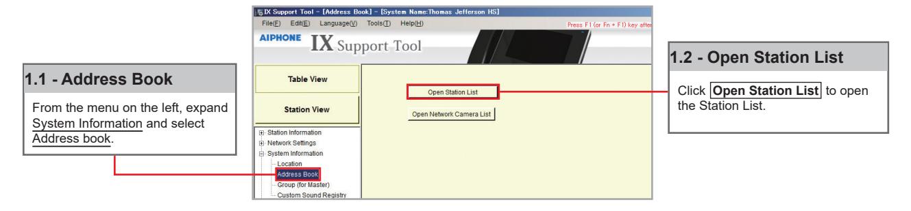
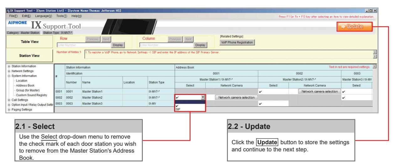
Step 2: Open Station List
By default, all stations within a system are in each Master Station's Address Book, represented on this page by a check mark. To remove a station from the Address Book, choose a Master Station and remove the check mark of a station from its list.
Door Station
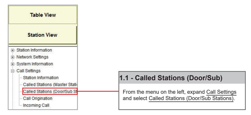
Step 1: Called Stations
To partition door/sub stations, find Call Settings on the left-hand menu and select Called Stations (Door/Sub Stations).
Partitioning a System
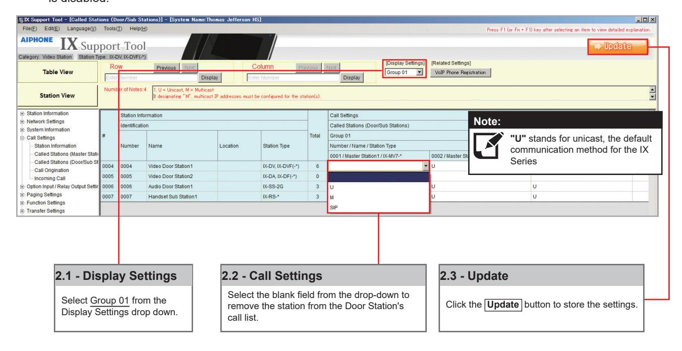
Step 2: Call List Partitioning
Station Type: IX-DV, IX-DVF(-*), IX-SSA(-*), IX-SS-2G, IX-RS-*
The above station types will default to calling Group 01. On the Called Station for Door/Sub Stations page, select Group 01 from the Display Settings drop down. There will be a list of all Door and Master Stations, with a " U" between each by default. A " U" represents call-in between these stations is enabled; a blank space means call-in is disabled.
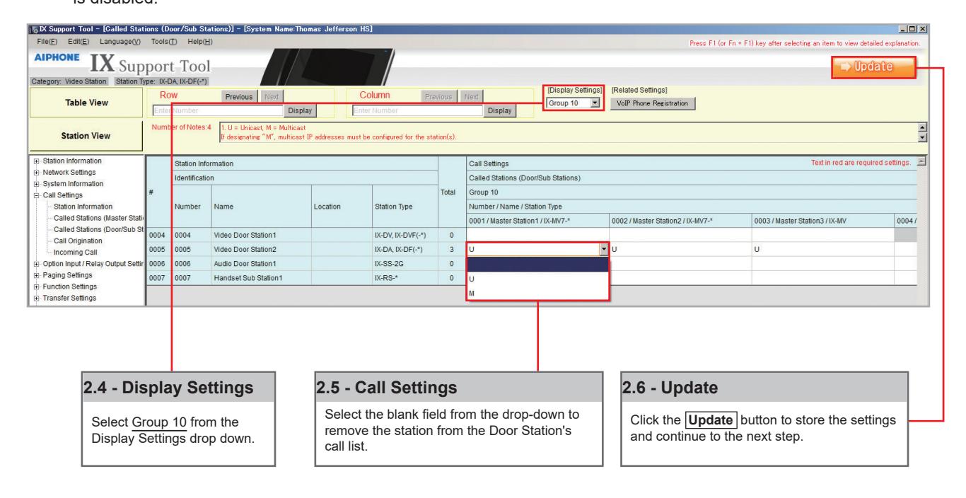
Station Type: IX-DA, IX-DF (-*), IX-BA, IX-SS(-*)
The above station types will default to calling Group 10. On the Called Station for Door/Sub Stations page, select Group 10 from the Display Settings drop down. There will be a list of all Door and Master Stations, with a " U" between each by default. A " U" represents call-in between these stations is enabled; a blank space means call-in is disabled.
Partitioning a System
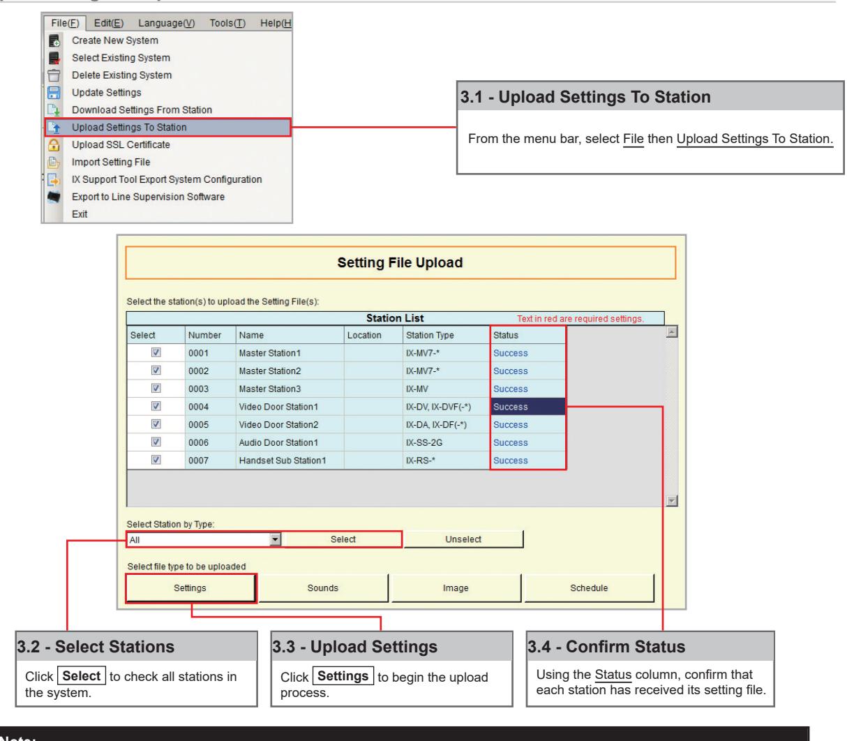
Step 3: Setting File Upload
The final step in this process is uploading the setting file to each station. This program file contains the system partitioning created in the previous steps, as well as any other setting configuration changes made.
Note that without uploading a setting file, most functions and features will be unavailable to the stations.
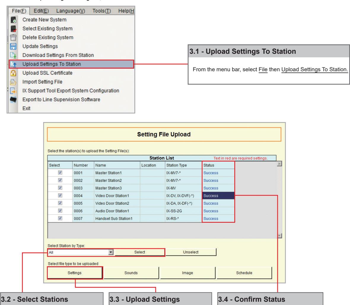

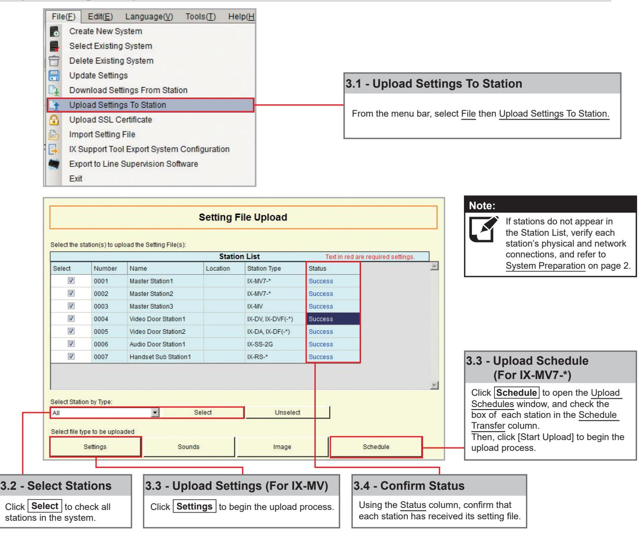
the system.
Click Select to check all stations in
It is recommended that a copy of the settings be saved after uploading settings to the stations. Refer to page 7 of this guide for the procedure to export and save settings.
Click Settings to begin the upload
process.
Using the Status column, confirm that each station has received its setting file.
Getting Started
The IX Series offers three types of call transfers: Absent, Delay, and Schedule. Before configuring a Transfer Setting, refer to page 14 for help partitioning an IX Series system.
The amount of time set for each station's Call Timeout (Call Settings > Call Origination) should take into consideration the longest possible time a call will need to reach the final transfer destination. For example, a Door Station calling into a Master Station using a Delay Transfer to up to two other Master Stations should have a Call Timeout set to 90 seconds. 30 seconds for the initial call, up to 30 seconds for the first transfer, and 30 seconds for the second.
Absent Transfer
Absent Transfer is meant to be turned "On" or "Off" by manually pressing the Transfer button on the Master Station. If Absent Transfer is "On", an incoming call will immediately be transferred when received by the Master Station.
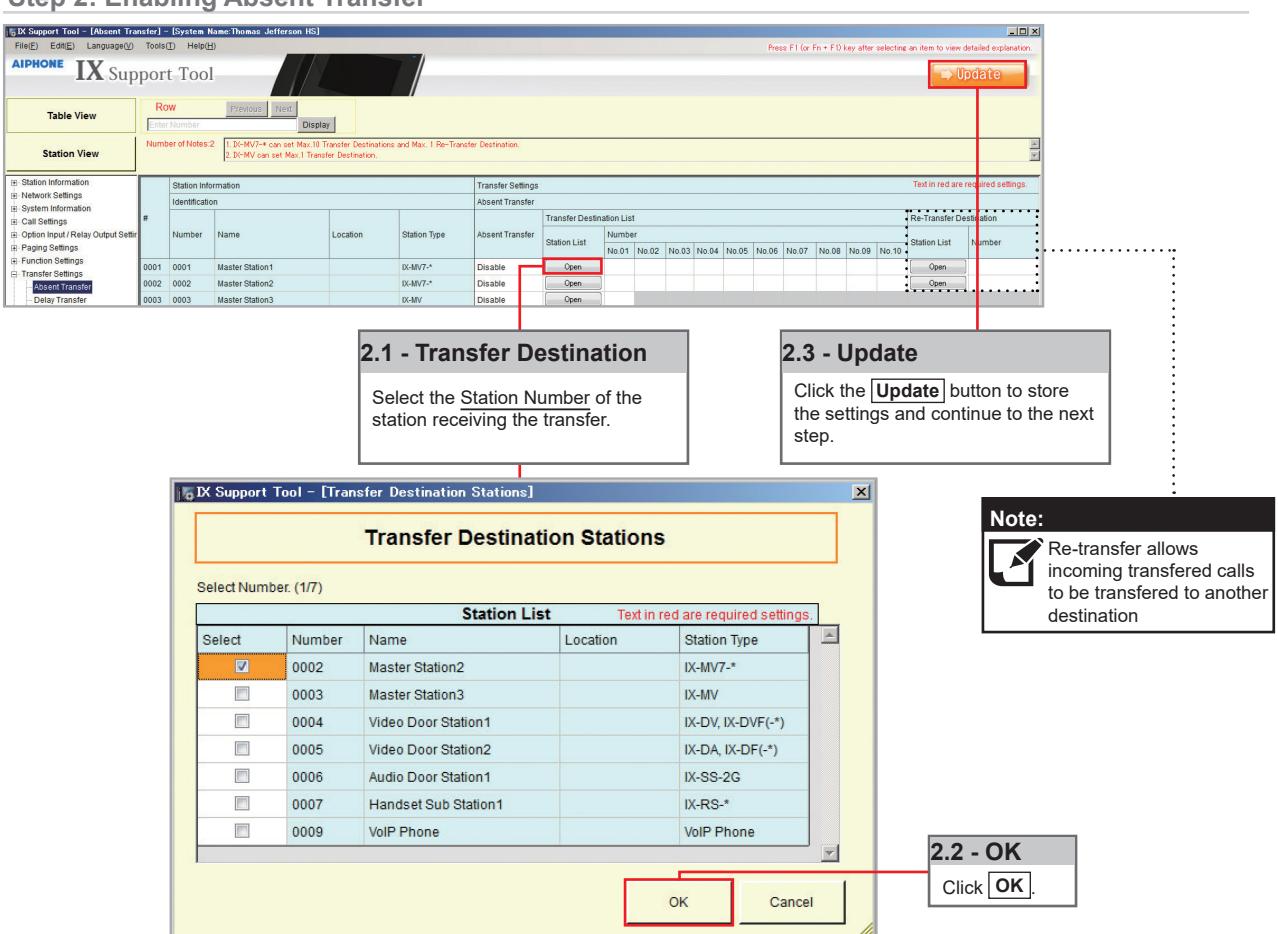
Note: To avoid call transfer loops, two stations should not be set to transfer to the other. Every station should have a unique transfer destination.
Step 1: Opening Absent Transfer
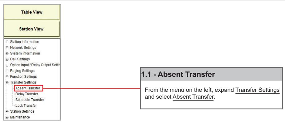
Step 2: Enabling Absent Transfer
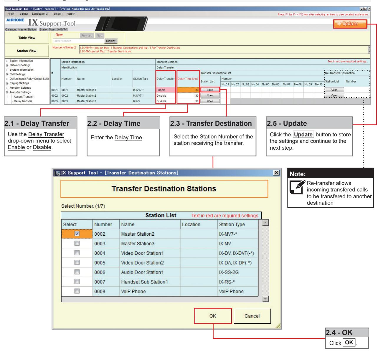
Delay Transfer
Delay Transfer should be used if a station should receive an incoming call and then transfer that call to another Master Station after a predetermined amount of time (in seconds).
Step 1: Opening Delay Transfer
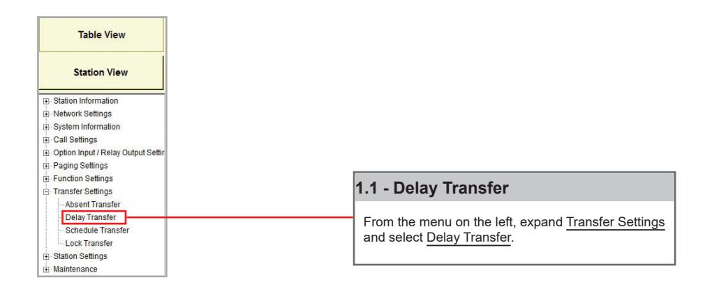
Step 2: Enabling Delay Transfer
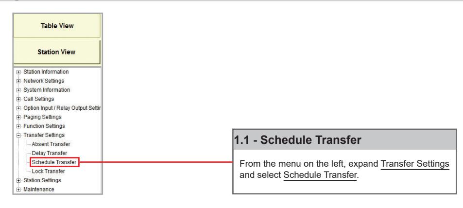
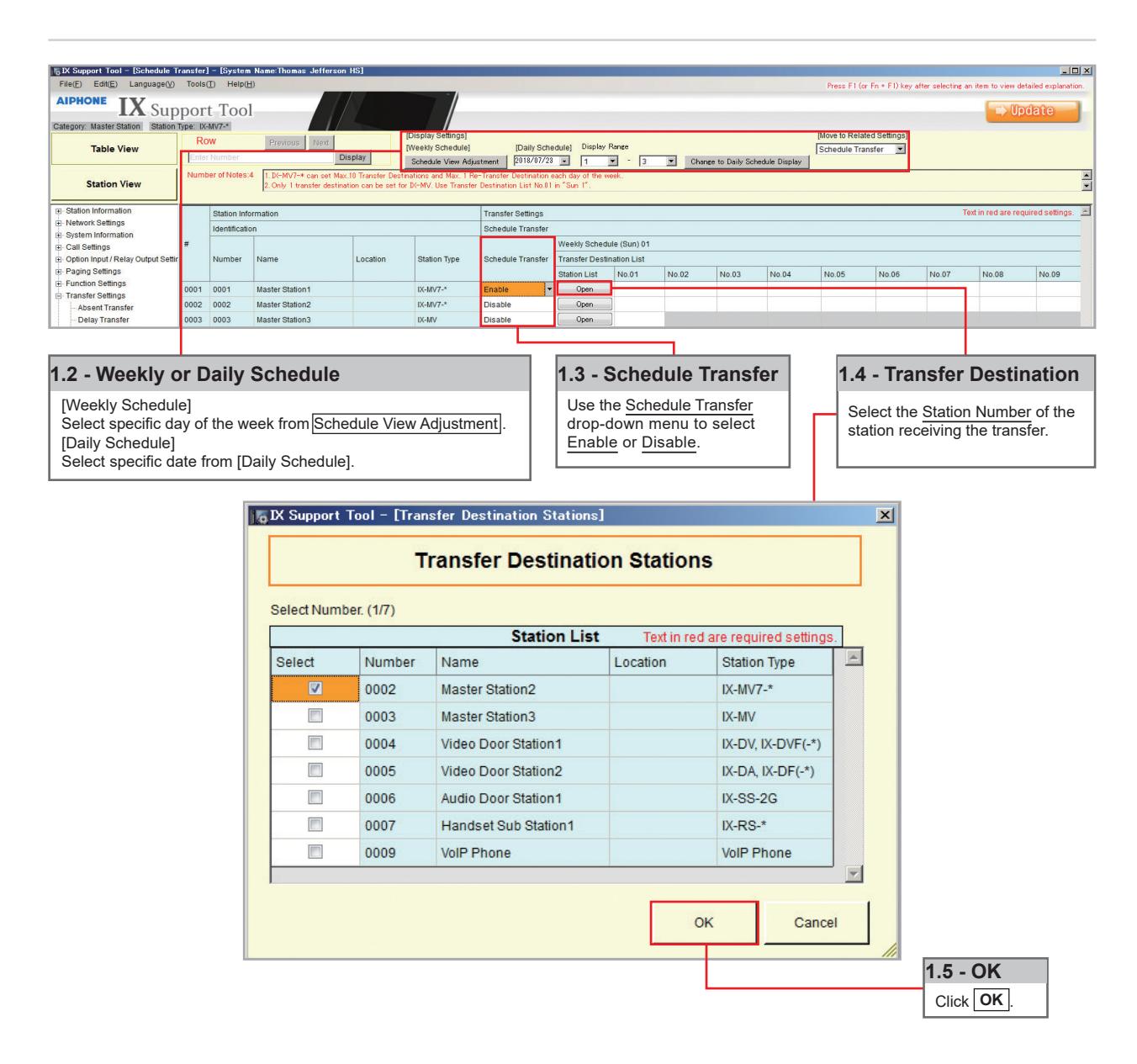
Schedule Transfer
Schedule Transfer can be used in scenarios when a call should be transferred from a Master Station based on a predetermined daily or weekly schedule.
Note: To avoid call transfer loops, two stations should not be set to transfer to the other. Every station should have a unique transfer destination.
Step 1: Opening Schedule Transfer
Step 2: Schedule Transfer Start and End Time
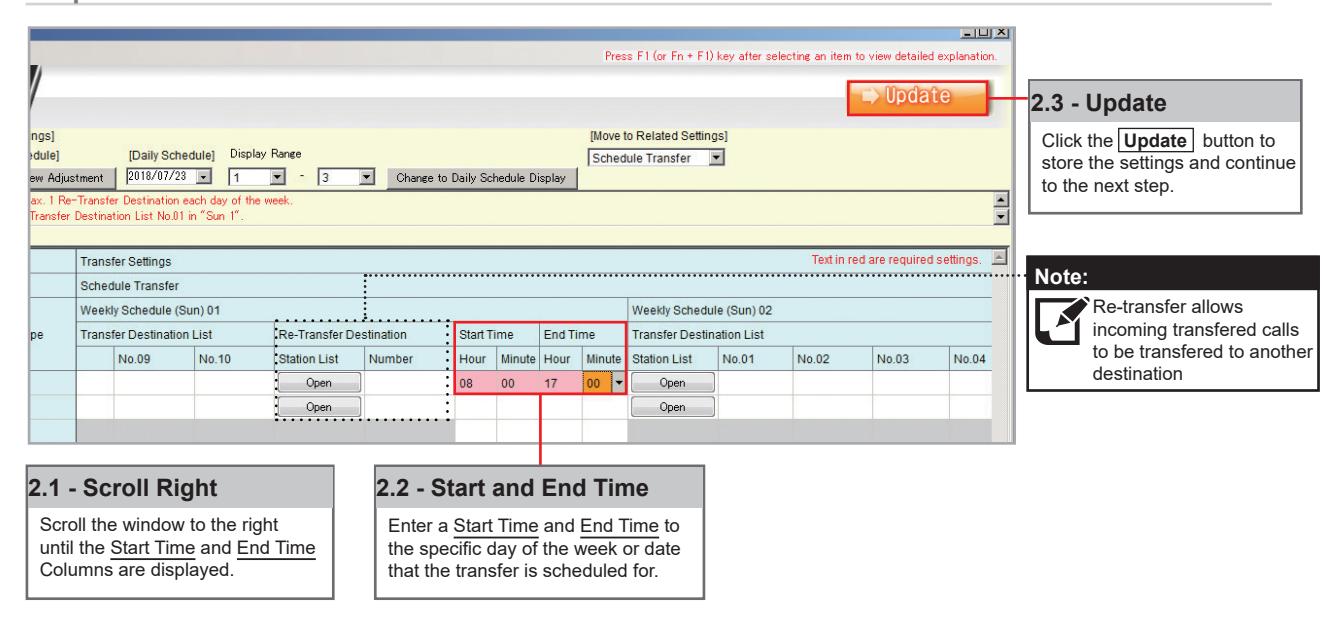
Uploading
The final step in this process is uploading the setting file to each station. This program file contains the transfer settings created in the previous steps, as well as any other setting configuration changes made.
Note that without uploading a setting file, most functions and features will be unavailable to the stations.
Step 3: Setting File Upload
Getting Started
To add a new station to an existing system, the existing program file is needed as well as network connection to all existing stations. Ensure the new station is connected to the network and has completed its initial boot up before starting step one.
Step 1: Opening the "Add New Station" Window
There are several ways to add a new station in Support Tool. The following method is done by returning to the System Configuration page.
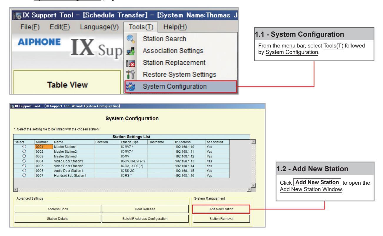
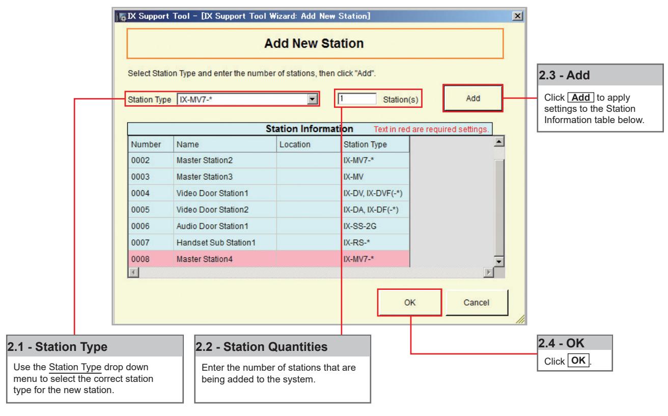
Step 2: Adding a New Station
New stations can be added in batches by station type.
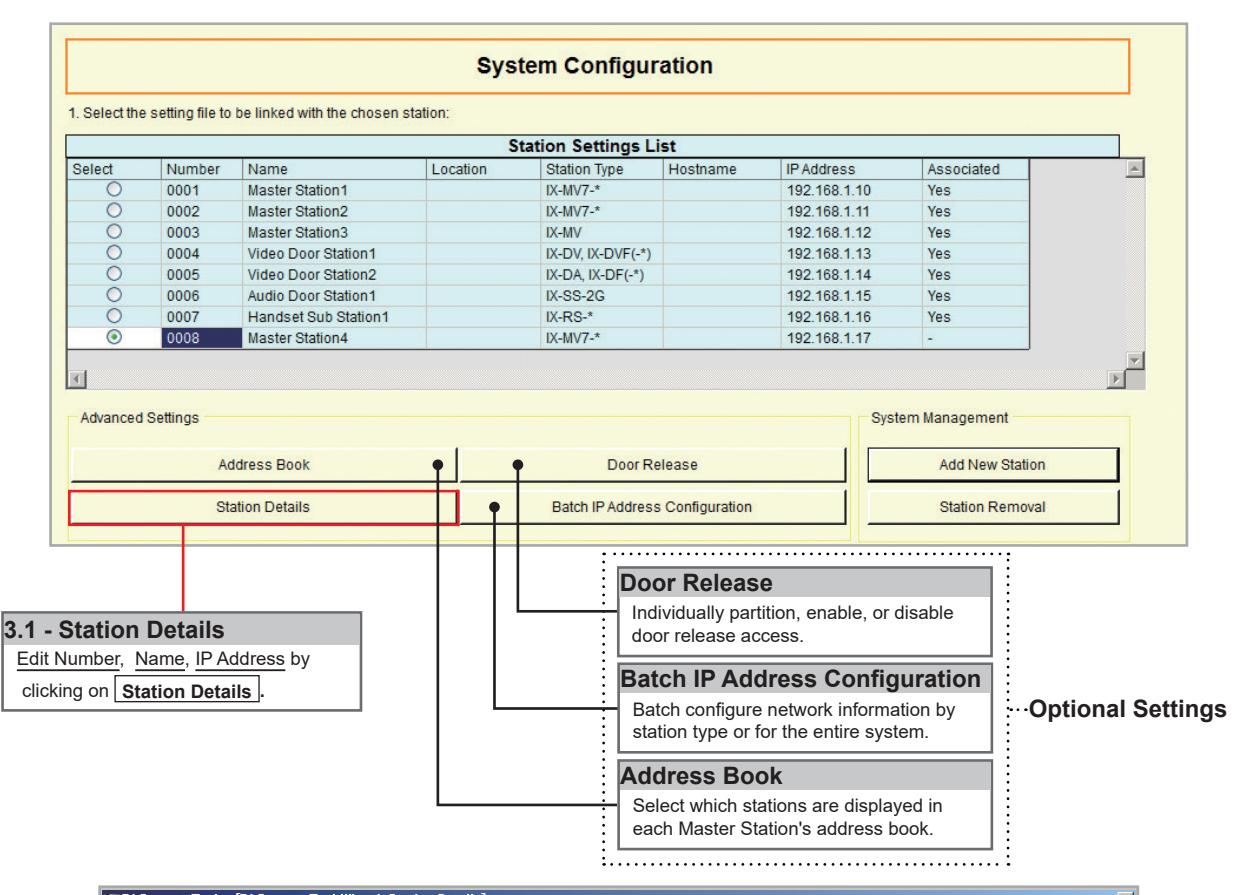
Step 3: Station Customization - Optional
Support Tool will provide each station a default Station Name, four-digit Number, and IP Address starting from 192.168.1.10. To edit this information, click Station Details in the Advanced Settings section, shown below. To use the default information created by Support Tool, skip to Step 4.
Step 4: Association
The association process is where the station information created in Support Tool is associated with a station found on the network. Choose one of two methods, Automatic (recommended) or Manual (page 6). Once associated, the station will receive its Station Name, Number, and network information after a short power cycle.
Step 5: Setting File Upload
Once each station has been associated with its individual station information, the setting file containing the rest of the system's information will need to be uploaded to each device. To upload the setting file, the programming PC will need to be in the same subnet as the associated stations (refer to Step 4). The PC's current IP address is listed in the bottom left-hand side of this window.
Note that without uploading a setting file, most functions and features will be unavailable to the stations.
Step 6: Export Settings
The final step in this section is to create a copy of the system's setting file and exporting it to a secure location or external drive.

If the original program file is lost, or Support Tool is moved to a different PC, this copy can be used to access the system programming to add or remove a station, or to make programming changes.

AIPHONE CO., LTD., NAGOYA, JAPAN
Issue Date: Feb.2019 FK2465 Ⓑ 0219 MQ 61339