Aiphone C-123LW Supplemental Instructions
Open the original PDF document
View PDF

C-123LW Supplemental Instructions
Dual Master ChimeCom System
- REFER TO INSTALLATION MANUAL INSIDE C-123L/A BOX FOR STANDARD INSTALLATION INFORMATION -
The C-123LW Dual Master ChimeCom set provides chime, communication, and door release for one door and two inside locations. This supplemental instruction manual addresses many of the additional functions and modifications for the Chime Com system, including installation and troubleshooting information.
MASTER STATION:
C-ML/A: Master station with door release button (Normally Open)
COMPATIBLE DOOR STATIONS: (Weather resistant, made for outdoor use)
C-D Surface mount, included in C-123L/A and C-123LW kit
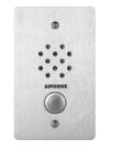
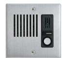
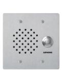
LE-D Surface mount, plastic door station (replacement for C-D) LE-DA Flush mount in 2-gang box, stainless steel cover LE-SS-1G Vandal resistant, 1-gang flush mount, stainless steel LE-SS/A Vandal resistant, 2-gang flush mount, stainless steel
LE-SSR Vandal resistant, 2-gang flush mount, stainless steel, red mushroom button
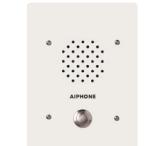
LS-NVP/C Vandal resistant, 3-gang flush mount, white powder-coat finish
OPTIONAL COMPONENTS & ACCESSORIES:
RY-AC/A External signaling relay (Requires 12VDC power supply)
DAK-2S Dual master adaptor kit (2component modules)
(1 kit per 2 master stations. Use 2 DAK-2S for up to 4 total master stations)
SBX-1G Surface mount box for LE-SS-1G
SBX-2G Surface mount box for LE-SS, LE-SSR, LE-DA
SBX-NVP Surface mount box for LS-NVP/C
EL-12S Door strike (for interior wood frame doors only) PT-1210N AC 12V Transformer (used for door strike) SKK-620C 6V DC power supply (1 per C-ML/A master)
822202 2 conductor, 22AWG, Shielded wire for up to 245', (500' and 1000' boxes)
821802 2 conductor, 18AWG, Shielded wire for up to 590', (1000' box)
Install two separate runs of this cable, one for the intercom and one for
the door release.
C-123L/A Set
LE-SS-1G
LE-DA
LE-SS
LS-NVP/C
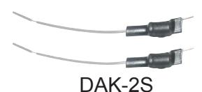
(2 component modules per kit)
DOOR RELEASE WIRES MUST BE IN A SEPARATELY JACKETED CABLE FROM THE INTERCOM WIRING.
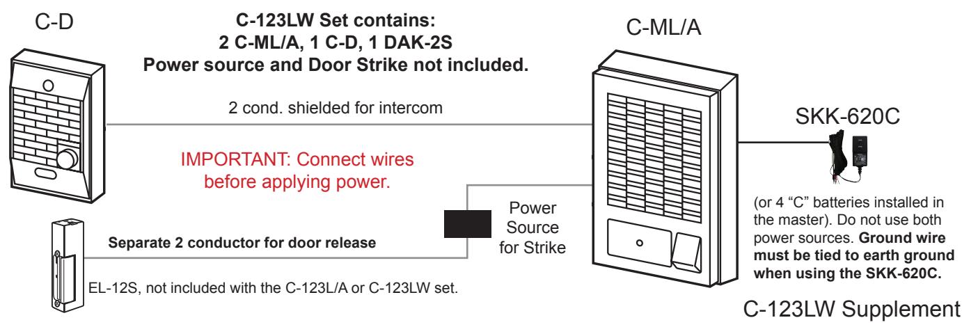
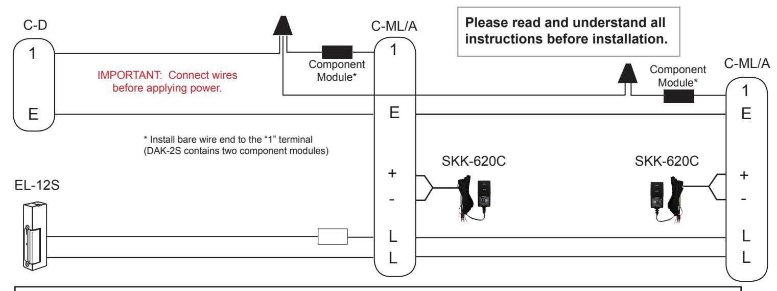
WIRING DIAGRAM: Dual Master Chime Com System with DAK-2S Dual Master Adaptor
IMPORTANT!!!
Each master REQUIRES an SKK-620C power supply, or 4 "C" batteries. (Do not install both on one C-ML/A.)
OPERATION NOTES:
- 1. Only one master can be used at a time.
- 2. If both masters are activated, a feedback (squeal) will be heard through the system when either TALK button is pressed.
- 3. If feedback occurs, wait approximately 15 seconds, or until the masters turns off automatically. At that time, communication can continue normally.
INSTALLATION GUIDELINES:
- 1. Run 2 conductor wire from the door station to the first master, then continue to the second master.
- 2. Install the units at the desired locations. (Do not install stations back to back on opposite sides of a wall.)
- 3. Separate SKK-620C power supplies or four "C" batteries are required for each master station.
- 4. DO NOT install both a power supply and batteries at any one master.
- Install the bare wire leg of the component module directly onto the "1" terminal of the C-ML/A's.
- 6. Attach the wire coming from the "1" terminal of the C-D to the colored wire end of the component modules at both masters. (The component modules will easily fit inside the space available.)
- 7. Connect the "E" terminals between the door station and master stations.
- 8. If door release is included, use a separate 2-conductor wire from the "L" terminals of the masters through an AC transformer and to the door strike.
- 9. The EL-12S is designed for a standard wood framed door, and for light to medium usage. If a different type of door is in place, install a strike appropriate for the door.
- 10. The door release button on the master station is a "Normally Open" contact closure for an electric strike. See page 3 for modification to "Normally Closed" if a magnetic lock is used.
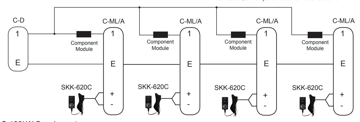
4 C-ML/A Master Stations with 1 Door
Note: In a multi-master system, all masters only talk to the door station, and only one master can be on at a time
C-123LW Supplement
Pg. 2
WIRING DIAGRAM: LEM-1DL System with External Signaling using RY-AC/A Relay
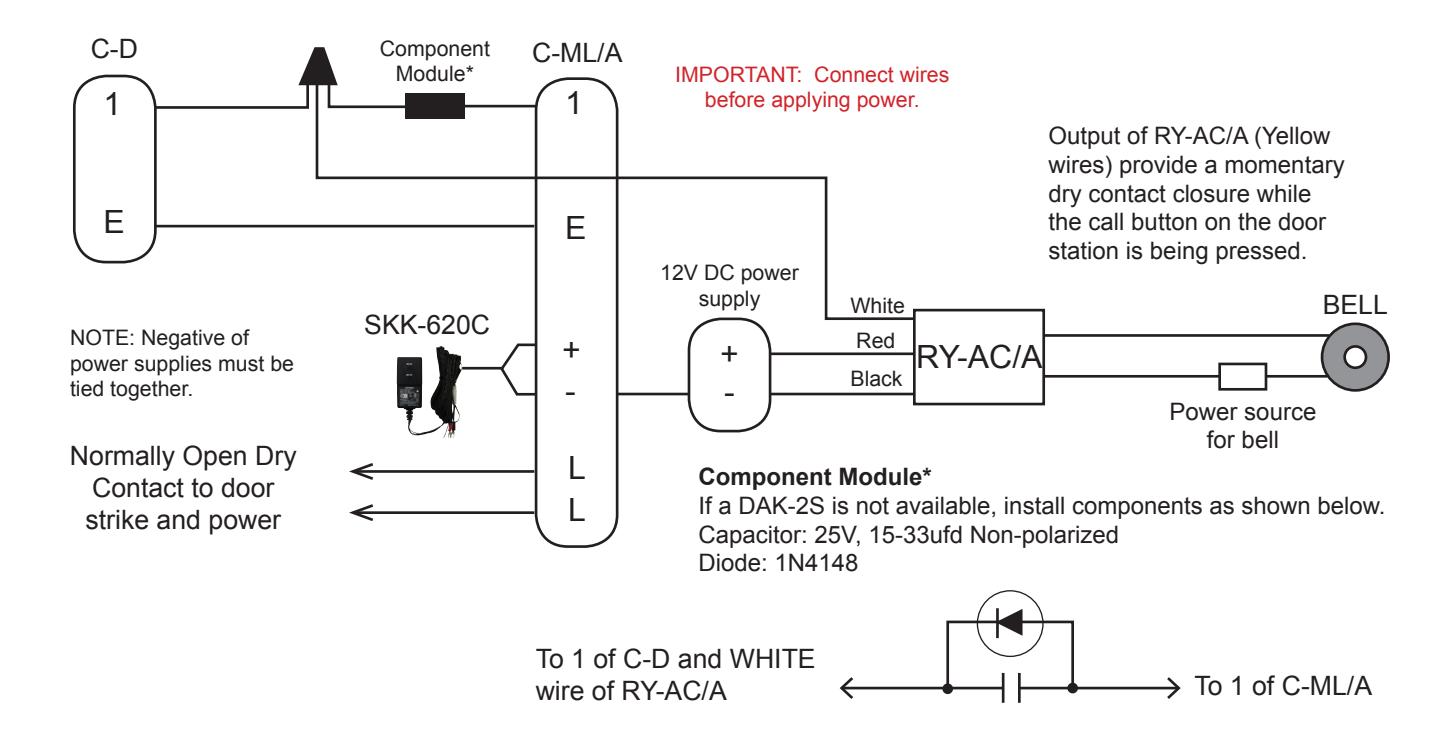
MODIFICATION INSTRUCTIONS:
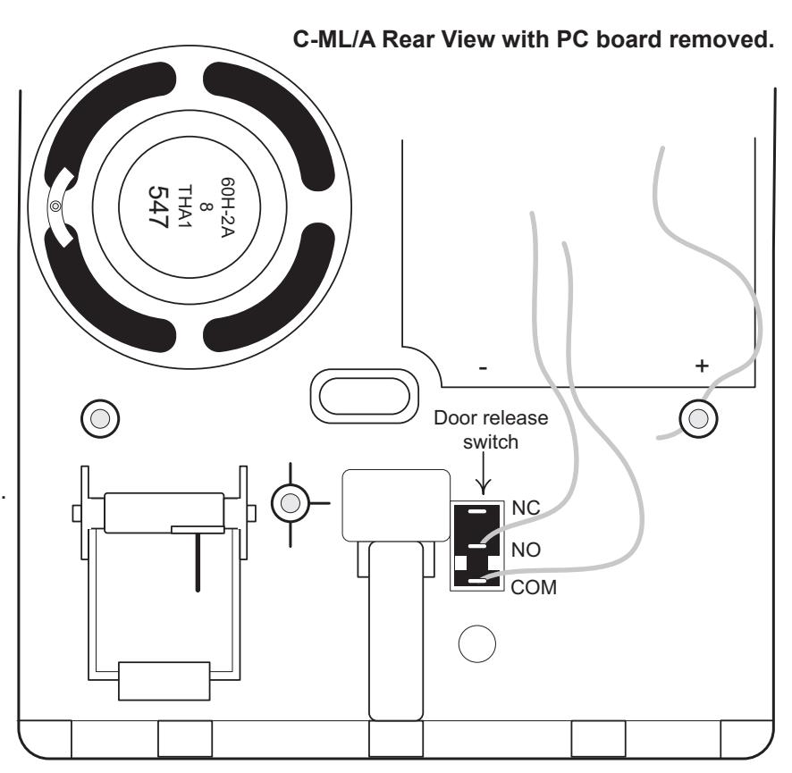
C-ML/A with Door Release contact Modified to Normally Closed (for Magnetic Lock)
Magnetic locks require Normally Closed contacts, keeping power applied to the magnet to keep the door locked, and breaking power to release the door. These instructions explain how to change the contact in the C-ML/A to Normally Closed.
- 1. Remove back chassis of C-ML/A and move the PC-754 board aside. Black door release switch will be visible.
- 2. On the switch, move* the wire from the NO contact (middle position) to the NC contact (top position). *Desoldering and resoldering is required.
- 3. This modification will change the door release button's function to Normally Closed, to be used with magnetic lock device.
- 4. Switch contact rating is 1A at 50V AC.
INSTALLATION TIPS:
- 1. Use shielded wire for the communication path, and ground one end of the shield to an earth ground.
- 2. Run intercom wire at least 20" away from AC wiring, fluorescent lights or dimmer switches.
- 3. Keep intercom cable away from alarm, data, phone, video cables, and any other potential source of interference.
- 4. Door release wires must be in a separately jacketed cable from the intercom wires. Use two separate cables; one for audio and one for door release.
- 5. When installing a second master station, wire must be run from the first master station, not from the door station. See diagram on page 2.
- 6. Do not install the master station near light switches, dimmer switches, or other devices that may cause interference with the intercom system.
- 7. Do not install the master station on the opposite wall from the door station. If the units are too close, acoustical feedback may result.
TROUBLESHOOTING GUIDE:
| PROBLEM | POSSIBLE CAUSE | SOLUTION |
|---|---|---|
|
No call in from door to master, but
communication works fine. |
Reversed DAK-2S component module. |
When door calls in, it shorts the #1 terminal to the E terminal.
If the DAK-2S is installed backwards the chime from the door call-in will not be heard. Install the DAK-2S component module with the bare wire under the 1 terminal, and the door station 1 wired to the colored wired end of the DAK-2S. |
|
When the talk button is pressed, the other
master rings. |
Missing or reversed DAK-2S
component module. |
Install the DAK-2S component module as described above
and shown on the dual master instructions. |
|
When the talk buton is pressed, feedback is
heard at both masters. |
Common power supply. |
If both C-ML/A's share the same power supply, a ground loop
feedback will occur when the talk button is pushed. Install a separate power source for each master. |
| Unit appears dead; No functionality | Terminals 1 and - crossed |
+/- are on left column, E/1 are on right column. If swapped,
unit will appear dead. Verify that 1 from the door station is connected to 1, and negative of power supply is connected to |
| System squeals and batteries get hot |
Power supply and batteries both
installed. |
Take batteries out of the master station. Both power sources
cannot be used simultaneously. |
| Chime tone sounds weak, low frequency | Weak batteries or low voltage. |
If batteries are installed, replace them. If using a power supply,
check for 6VDC. If low, install a new SKK-620C. |
| Master stays on; does not time out. | Incorrect cable being used. |
If the resistance of the wire is too great, usually from
exceeding distance limitations, the master may not time out as designed. Refer to wire specifications in the instructions. |
| Voice volume is too loud or too soft. | Volume control not adjusted properly. |
Remove front cover of the C-ML/A and locate volume
potentiometer through hole at bottom of unit. Use a small screwdriver to adjust the volume, clockwise to increase. |
| Chime tone volume is too loud. | Standard volume level. |
There is not a separate call tone volume adjustment on the
C-ML/A so the volume level cannot be altered. Surface mount component level modification would be required, which is not paractical. |
| RY-AC/A external signaling relay not working. | Missing or wrong connection. |
Make sure the negative from the 12VDC supply for the RY-AC/A
is connected to the negative of the C-ML/A master. Make sure the WHITE wire of the RY-AC/A is connected to the DAK-2S component module to terminal 1, not negative terminal. |