Aegis Power Cell Removal and Replacement
Open the original PDF document
View PDF

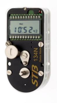
Aegis Digital Time Movement Power Cell Removal and Reinstallation 114E, 134W & 134N Movements
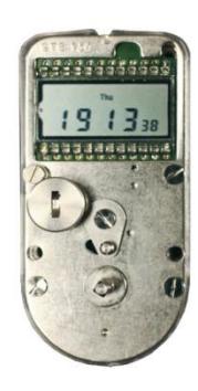
Removal of the power cell is required to reset some of the Aegis movements for programming or to replace the power cell with a fresh one. Digital movements are designed to fail safe. This means that if the cell power is inadequate, the movement will fail to arm and instantly release. A universal battery symbol will appear in the lower right-hand corner of the LCD display indicating that there is inadequate power for locking. Unless you have been trained in how to change these power cells, contact a qualified service technician. Annual inspection and replacement of all power cells is recommended.
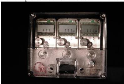
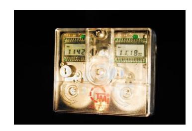
Remove the Plexiglas front cover. The three (3) movement assembly cover is retained by 4 hexagonal screws located at each corner of the assembly. The two (2) movement assembly covers are first retained with a cross tip screw at the top center of the assembly and then removing the flat tip screw underneath to remove the larger cover.
Power Cell Removal
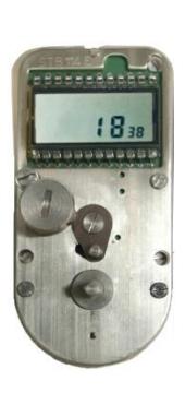
The power cell is located below and to the left of LCD display on each movement. To remove the power cell cap, use the head of the winding key to turn the power cell cap counterclockwise. Note: there will be a spring between the bottom of the cap and the power cell. Remove the power cell. If the power cell is being removed to reinitiate the movement, wait at least 30 seconds prior to reinstalling the power cell. If the power cell is being replace due to inadequate power, install a fresh Duracell #DL 1/3 N power cell. If the power cell is changed within a 10 second time span, all programming data will be retained by the 134 N movement. Never hold the power cell between the thumb and forefinger on the + and – poles of the battery simultaneously, as this could immediately discharge the power cell.
Power Cell Installation:
Ascertain that the power cell cap has the spring in it before securing the cell to the movement. Carefully insert the power cell with the + facing upwards. Reinstall the power cell cap by using the winding key head to gently push down and turning the cap clockwise. When installed correctly, the slot in the power cell cap will be vertical. When a new or existing power cell is installed the screen will show all 8's. If not present, remove and reinstall the power cell to achieve.
Reinstall the covers and refer to programming and operating instructions for the specific 114E, 134W and 134N models.
WWW.tmilock.com Corporate Headquarters : 127 SE 29th St • Topeka, Kansas 66605 • USA Tel. 785-232-8705 Fax 785-232-2603