Addendum to the Alarm Lock ETDL Cylinder Adapter Kit Addendum
Open the original PDF document
View PDF

CYLINDER ADAPTER KIT ADDENDUM
345 Bayview Avenue Amityville, New York 11701 For Sales and Repairs 1-800-ALA-LOCK For Technical Service 1-800-645-9440
© ALARM LOCK 2003
WI 1177 1/03
CAUTION PROPER ALIGNMENT OF GEARS IS CRITICAL!
FAILURE TO ALIGN GEARS PROPERLY WILL CAUSE LOCK TO MALFUNCTION.
Note: See the illustrated instructions, WI 1163, "How to Replace Cylinder" for detailed replacement procedures. After inserting the new cylinder and Slide Plate, and before replacing the Cover Plate (step 16), align the gears as follows:
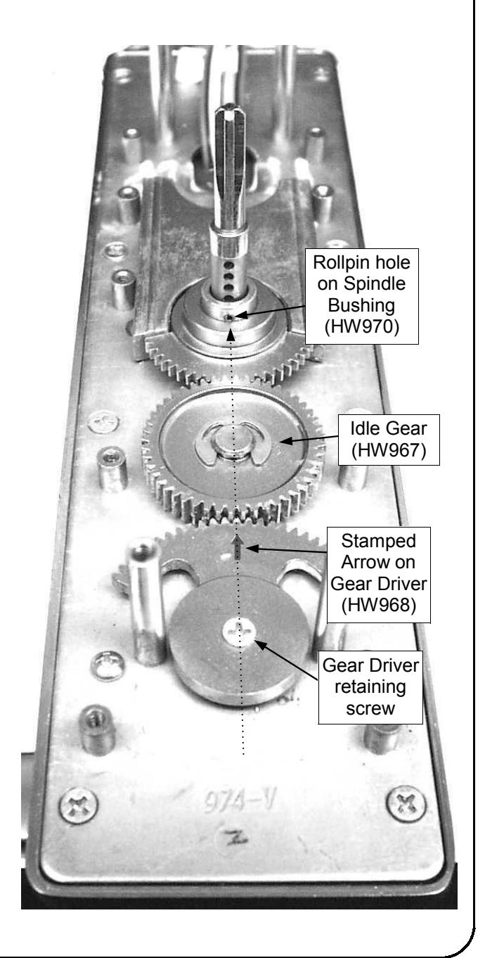
The rollpin hole located on the Spindle Bushing (HW970) must be aligned with the stamped arrow on the Gear Driver (HW968). Using a straight edge (or for convenience you can use the Cover Plate HW1016 instead of a straight edge) align the gears as shown in the illustration at right:
Place one end of the straight edge directly over the center retaining screw of the Gear Driver. Align the other end of the straight edge with the rollpin hole. The stamped arrow (!) on the Gear Driver must be directly underneath the straight edge when aligned with the rollpin hole.
If the arrow is not aligned, loosen the Gear Driver retaining screw, lift the Gear Driver. The Slide Plate springs will cause the Spindle Bushing to self-align (if the Slide Plate is installed properly). Re-position the Gear Driver until the arrow is aligned with the rollpin hole. Tighten the Gear Driver Retaining screw, and Replace the Cover Plate and Frame Spacer as per the directions in WI 1163.