Addendum Instruction Sheet for Low Profile Locks (Cylindrical,Mortise,Exit Devices)
Open the original PDF document
View PDFAddendum Instruction Sheet for Low Profile Locks, Cylindrical, Mortise, and Exit Device
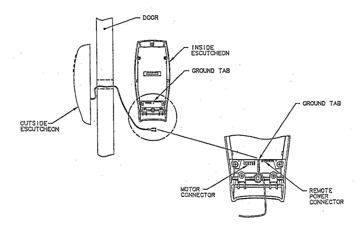
1. The Low Profile Lock is provided with a ground wire attached to the Outside Escutcheon assembly (See Figure 1). During the installation of the lock to the door, the ground wire is routed through the hole in the door used by the keypad wire assembly (ribbon cable) and attached to the ground tab (E3) on the controller PCB (See Figure 2).
Note: The purpose of the ground wire is to provide a reliable connection between the Inside and Outside Escutcheons for the purpose of dissipating static electricity.
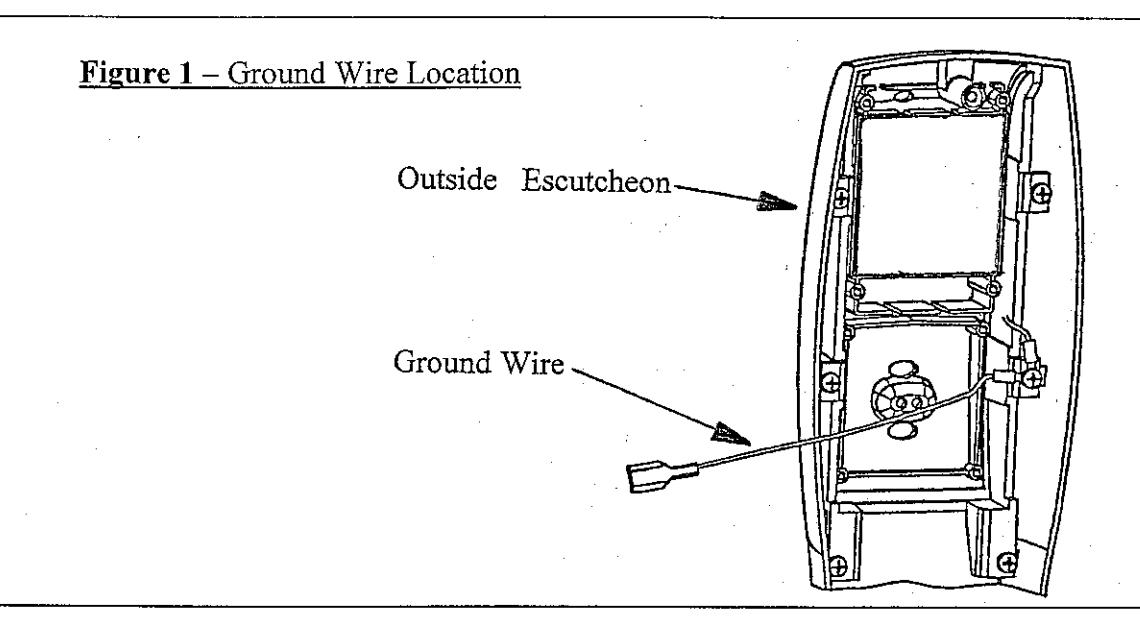
Figure 2 - Ground Wire Routing to Ground Tab (E3)
Addendum Instruction Sheet for Low Profile Locks, Cylindrical, Mortise, and Exit Device
2. The following diagram (See Figure 3) illustrates the correct installation of the motor harness connector onto the Controller PCB when viewed as shown. Correct orientation of the connector is critical for proper operation of the motorized lock. Verify connector orientation prior to mounting the Inside Escutcheon to the door.
Figure 3 - Motor Harness to Controller PCB Installation Diagram Inside Escutcheon Motor Connector Lock Body Wire Harnesses BROWN RED RED BLACK BLAĆK GREEN RED GREEN ORANGE 8200 Mortise 10-Line & 8200 Mortise YELLOW with Deadbolt without Deadbolt Motorized ET 8800/8900
This document supplements the following instruction booklets: A7453, A7454 and A7455