Adams Rite PS-EXIT Power Supply Installation Instructions
Open the original PDF document
View PDFPS-Exit Exit Device Power Supply

Installation Instructions
Overview
The Adams Rite PS-EXIT power supply provides power and control for up to two MLR or LR exit devices. Each exit device is controlled by a timer that is initiated by a switch closure. The timer is user-configured and holds the exit device(s) in the unlatched position for 2 – 60 seconds. At the end of the selected time, the exit device(s) will re-latch. If the switch controlling the exit device is closed longer than the selected time, the exit device remains unlatched until the controlling switch is released.
- An optional mode is available that allows both retraction timers to activate in response to a closure of either switch.
- The PS-EXIT is listed as an Exit Device, Access Control System Unit to UL294 requirements for power supplies and Canadian Standards CAN/CSA - C22.2.
- Exit devices under access system control remain latched during a complete power failure but always allow free mechanical egress.
Specifications
PART NUMBERS & LOCATIONS
| CIRCUIT BOARD | PART NUMBER | LOCATION |
|---|---|---|
| PS-EXIT | 31-0725 | Power Supply |
| Battery Backup System Kit | BBK-EXIT | Power Supply |
PS-EXIT VOLTAGE MEASUREMENTS
- OUT1/OUT2 when IN1/IN2 is OPEN: less than 1.6 VDC
- OUT1/OUT2 when IN1/IN2 is CLOSED: 24 26 VDC
- OUT1/OUT2 are rated at a maximum output current of 400 mA each.
LED INDICATORS
| LED | COLOR | STATUS | |
|---|---|---|---|
| Main Power |
RED
ON when AC power is on |
||
| FIRE |
GREEN
ON if no fire alarm condition |
||
|
OUT1
GREEN ON during OUT1 unlock time interval |
|||
|
GREEN
ON during OUT2 unlock time interval OUT2 |
|||
|
IN1
GREEN ON when contacts at IN1 are closed |
|||
|
GREEN
ON when contacts at IN2 are closed IN2 |
|||
NOTE: The board must be replaced if OUT1 is on when IN1 is open or if OUT2 is on when IN2 is open.
PS-EXIT IS CLASSIFIED UNDER THE FOLLOWING UL294 PERFORMANCE LEVELS
- Endurance, Level IV
- Line Security, Level I
- Destructive Attack, Level I
- Standby Power, Level IV (with battery backup system BBK-EXIT)
Connector & Signal Descriptions
| CONNECTOR | PIN | DESCRIPTION | |
|---|---|---|---|
| 1 | 24-V (+) from battery charging system during AC fail | ||
| J1 | 2 | 24VDC supplied to battery charging system | |
| Battery Backup | 3 | 24-V return | |
| 1 & 2 | Input #2, normally-open activation switch input | ||
| 3 & 4 | Input #1, normally-open activation switch input | ||
| 5 | Exit Device #2 return | ||
| J3 | 6 | Exit Device #2, +24 VDC when activated | |
| Field Wiring | 7 | Exit Device #1 return | |
| 8 | Exit Device #1, +24 VDC when activated | ||
| 9 & 10 | Fire alarm interface, normally-closed (no alarm) input | ||
| L | Main (AC) power live/hot input | ||
| J4 Main Power | N | Main (AC) power neutral/return input | |
| Safety ground screw | Connection point for AC safety ground | ||
NOTES: Fuse F2 is not user-serviceable. If replacement is needed, it must be returned to the factory. The maximum RMS input current to the PS-EXIT is 0.70 A at 115 VAC.
Configure the PS-EXIT
NOTE: PS-EXIT is rated for 115 VAC only. Switch 2 (SW2) is factory preset for 115 VAC operation.
- 1 ENSURE that PS-EXIT is set to 115 VAC as shown in Diagram 1.
- 2 SET the desired operating mode with DIP-switch 1 on SW1 as shown in Diagram 2. NOTE: PS-EXIT has two operating modes. PS-EXIT is factory-preset for single-input operation.
SINGLE INPUT (SEQUENTIAL OPERATION)
APPLICATION: control double-door exit with one input. OPERATION: either input retracts the corresponding exit followed by retraction of the second device.
DUAL INPUT (INDEPENDENT OPERATION)
APPLICATION: control two separate exits with two inputs. OPERATION: Input IN1 retracts device connect to OUT1. Input IN2 retracts device connect to OUT2.
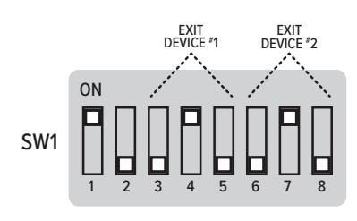
Configure the Unlock Times
NOTE: PS-EXIT has two unlock timers.
1 To configure the unlock time for OUT1, set DIPswitches 3, 4, and 5 on SW1 to ON/OFF for the desired unlock time listed in the table below. See the example settings shown in Diagram 3.
|
DIP
SWITCH |
2
SEC |
5
SEC |
10
SEC |
15
SEC |
20
SEC |
30
SEC |
45
SEC |
60
SEC |
|---|---|---|---|---|---|---|---|---|
| 3 | OFF | ON | OFF | ON | OFF | ON | OFF | ON |
| 4 | OFF | OFF | ON | ON | OFF | OFF | ON | ON |
| 5 | OFF | OFF | OFF | OFF | ON | ON | ON | ON |
2 To configure the unlock time for OUT2, set DIPswitches 6, 7, and 8 on SW1 to ON/OFF for the desired unlock time listed in the table below. See the example settings shown in Diagram 3.
|
DIP
SWITCH |
2
SEC |
5
SEC |
10
SEC |
15
SEC |
20
SEC |
30
SEC |
45
SEC |
60
SEC |
|---|---|---|---|---|---|---|---|---|
| 6 | OFF | ON | OFF | ON | OFF | ON | OFF | ON |
| 7 | OFF | OFF | ON | ON | OFF | OFF | ON | ON |
| 8 | OFF | OFF | OFF | OFF | ON | ON | ON | ON |
CAUTION
Damage to the PS-EXIT or to exit devices may occur if connections are not made in accordance with the following procedure, or if connections are bypassed or omitted.
DIAGRAM 1: Primary Voltage Setting
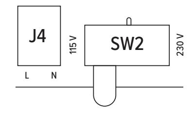
DIAGRAM 2: Dip Switch 1
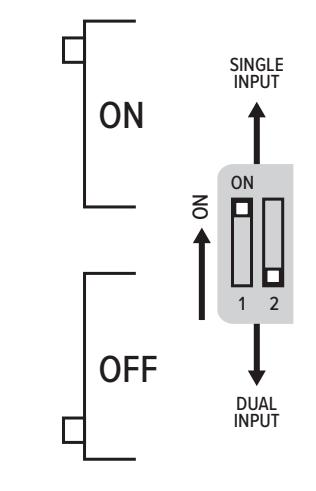
DIAGRAM 3: Unlock Times
Connect the Fire Alarm Interface
NOTES: If used with fire doors, PS-EXIT is required to be under the control of an automatic fire alarm control system. PS-EXIT is factory preset to be used without a fire alarm interface.
- 1 ENSURE that the installed jumper is in place at Positions 9 and 10 (FIRE) of Terminal Block J3 to use PS-EXIT without a fire alarm interface.
- 2 REMOVE the jumper and CONNECT the normally-closed relay contacts of the fire alarm interface to Positions 9 and 10 (FIRE) of Terminal Block J3.
NOTES: Closed relay contacts indicate no alarm condition.
In the event of a fire alarm, the exit devices immediately latch secure. Exit devices remain latched during a fire alarm but always allow free mechanical egress.
The maximum current through the fire alarm contacts is 10 mA at 24 VDC.
Connect the Input Control Switches & Exit Devices
3 CONNECT the normally-open activation switch (dry contacts) for Exit Device #1 to terminals 3 and 4 (IN1) on Terminal Block J3.
NOTE: The exit device is rated for continuous duty.
- 4 CONNECT the normally-open activation switch (dry contacts) for Exit Device #2 to terminals 1 and 2 (IN2) on Terminal Block J3.
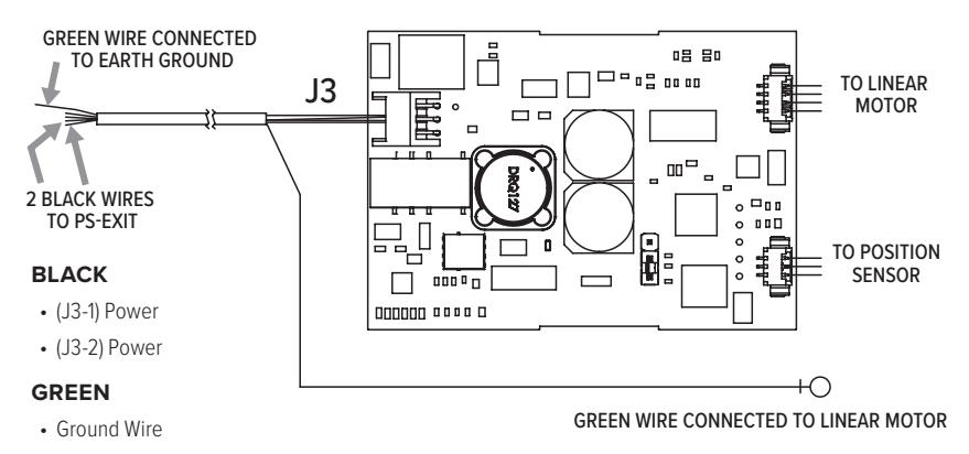
- 5 CONNECT the exit devices to PS-EXIT with wire lengths specified in the table. Exit device wiring is illustrated in Diagram 4.
| MLR | LR | |||
|---|---|---|---|---|
|
CABLE
LENGTH (FT) |
WIRE GAUGE
(AWG) |
CABLE
LENGTH (FT) |
WIRE GAUGE
(AWG) |
|
| 0 – 300 | 18 | 0 – 40 | 16 | |
| 300 – 600 | 16 | 40 – 60 | 14 | |
| 600 – 900 | 14 | 60 – 100 | 12 | |
DIAGRAM 4: Exit Device Wiring
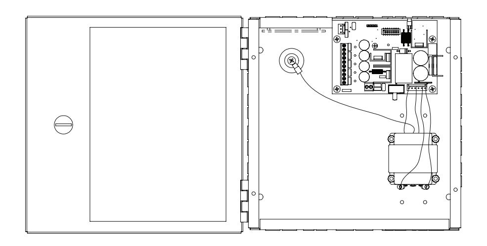
Mount the PS-EXIT power supply
- 1 MOUNT the PS-EXIT power supply close to the exit device (door) to be operated. For UL 294 compliance, PS-EXIT must be installed in a controlled/protected area. NOTES: Mounting holes are 1/4" in diameter. Enclosure dimensions are 10" x 10" x 4".
- 2 FASTEN the PS-EXIT power supply securely to the wall using the mounting holes located on the back of the enclosure.
INSTALL THE BATTERY BACKUP SYSTEM (BBK-EXIT)
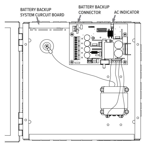
- 3 ORDER the BBK-EXIT Battery Backup System Kit and two 12 V, 7 AH batteries (EverOn EVA12-7.5F or equivalent). Install the BBK-EXIT along with the batteries in the PS-EXIT enclosure. NOTE: Mounting studs are provided in the PS-EXIT enclosure for the battery-backup circuit board.
- 4 INSTALL the Battery Backup System circuit board in the enclosure as illustrated in Diagram 5. NOTE: The Adams Rite Battery Backup System circuit board has a short wiring harness to connect to the PS-EXIT circuit board.
- 5 PLUG the orange connector of the wiring harness into the BATTERY BACKUP connector (J1) of the PS-EXIT circuit board.
- 6 CONNECT the red (+) and black (–) wires from terminal block BATT1 on the BBK-EXIT circuit board to the positive and negative terminals, respectively, of the first battery.
- 7 CONNECT the red (+) and black (–) wires from terminal block BATT2 on the BBK-EXIT circuit board to the positive and negative terminals, respectively, of the second battery.
DIAGRAM 5:
Battery Backup Location
Wire the Automatic Door Interface (Optional)
NOTE: This step is required to use PS-EXIT with an automatic door opener. Automatic door-opening systems need an indication of the latched state. The latch controller, located in the panic bar device, has relay contacts that signal the latched state to the automatic door opener. The relay contacts are closed when the latch is fully retracted and are open when the latch is extended.
1 CONNECT the automatic door opener as indicated in Diagram 6.
CONNECT PRIMARY (AC) POWER
NOTE 1: An earth ground must be connected to the PS-EXIT enclosure and to the push bar.
NOTE 2: Terminal block J4 accommodates up to 12 AWG wire for the 115 VAC input.
NOTE 3: A circuit breaker rated at 20 A must be provided for the installation.
- 2 CONNECT the AC line wire to the J4 terminal labeled L.
- 3 CONNECT the AC neutral wire to the J4 terminal labeled N. NOTE: An earth ground connection is provided inside the enclosure.
- 4 CONNECT the ground wire to the ground screw on the back wall of the PS-EXIT enclosure.
DIAGRAM 6:
Automatic Door Operator
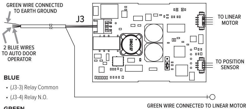
GREEN
• Ground Wire
Troubleshooting Guide
|
The exit device doesn't
unlock when connected to the access control system. |
1. ENSURE that the MAIN POWER and FIRE LEDs are on. If not, check AC power
and the fire alarm interface or fire alarm jumper. If operating on battery power, make sure the BATTERY BACKUP connector is properly seated. 2. ENSURE that switch SW2 (located next to transformer connector J5) is set to 115 VAC. 3. DISCONNECT access control from IN1 and IN2 and place a jumper wire at either IN1 or IN2. Set DIP-switch 1 on SW1 to ON. If the exit devices operate, check the access controller. |
|---|---|
| No power to the exit device |
ENSURE that the power connector at the exit device is properly
seated and that all wiring from the power supply to the exit is continuous and without short-circuits to ground. |
|
Neither exit device
retracts after the control switch is activated |
1. ENSURE that the exit device wires are securely
clamped at the PS-EXIT terminal block. 2. ENSURE continuity through power transfer devices, such as wired hinges and door cords/loops. |
|
Main Power LED (Red)
is not lit |
1. ENSURE that AC line voltage is present.
2. ENSURE that the Primary Voltage Selection Switch (SW2) is properly set. |
|
FIRE LED on PS-EXIT
Board is not lit |
ENSURE that there is a fire alarm interface connected between
J3-9 and J3-10 or that the factory-installed jumper is in place. |
|
IN1/IN2 LEDs do not light in
response to input switches |
1. CHECK to see if an open connection in the field wiring exists between
the PS-EXIT and the control switch used to activate the exit device. 2. CHECK if there is a defective control switch on J3-1 and J3-2 or J3-3 and J3-4. |
|
OUT1/OUT2 LEDs do
not light in response to input switches |
1. Replace PS-EXIT PCBA.
2. If one exit device works and one does not, perform the following: • PROP the door open. • CONNECT a voltmeter across the power leads coming from the exit device. • ACTIVATE the non-operational exit device. • If the voltmeter measures approximately 24 VDC at the time of activation and the device did not retract, replace the exit device. |
|
Exit devices retract even
though the control switch VERIFY that the controlling switch is in the open position. had not been activated |
|
8 of 8

adamsrite.com | 800 626 7590 techsupport.adamsrite@assaabloy.com 10027 S. 51st Street, Ste. 102 Phoenix, AZ 85044 USA