Adams Rite P8700 Pullman Exit Device Installation Instructions
Open the original PDF document
View PDF

P8700 RIM EXIT DEVICE INSTALLATION INSTRUCTION
whole or in part without the express written permission of Hanchett Entry Systems, Inc. is prohibited. 80-0180-348 1
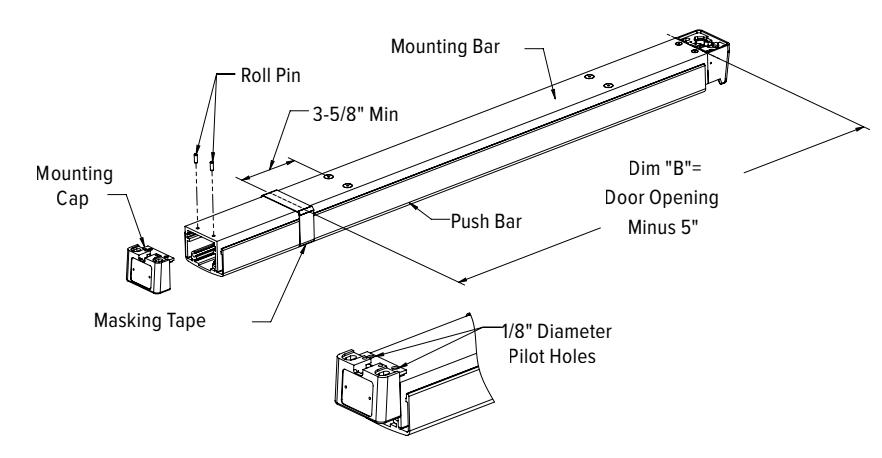
Cut-off Instructions for Non-standard Doors
- 1. Drive out two roll pins.
- 2. Remove mounting cap.
- 3. Collapse bar and tape down area of cut-off.
- 4. Determine extrusion length ("B" dim)
NOTE: 3-5/8" Minimum dimension from rivet centerline to new cut-off length as shown.
- 5. Measure mounting bar (not push bar) and mark extrusion length on tape.
- 6. Saw off excess length, remove tape and debur
- 7. Lay mounting cap over mounting bar and use as a guide to drill two 1/8" dia. holes.
- 8. Re-install mounting cap into mounting bar and drive two roll pins into holes.
Separating Push Bar and Mounting Bar Procedure
- 1. Remove both end caps
- 2. Slide push bar toward the hinge side of the door.
- 3. Continue to slide the push bar past the pivot plate that rides in push bar track.
- 4. Slide push bar in opposite direction keeping pivot plate out of track until pushbar is free of mounting plate.
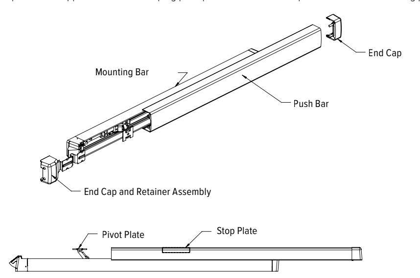
INSTALLING PUSH BAR TO MOUNTING BAR
With push bar in hand and mounting bar attached to door. Find stop plate staked into push bar (this plate is on the latch end of assembled unit). Slide the pivot plate nearest hinge into track of push bar until second pivot plate is exposed. Insert pivot plate into track on push bar and slide in opposite direction until push bar and mounting bar align.
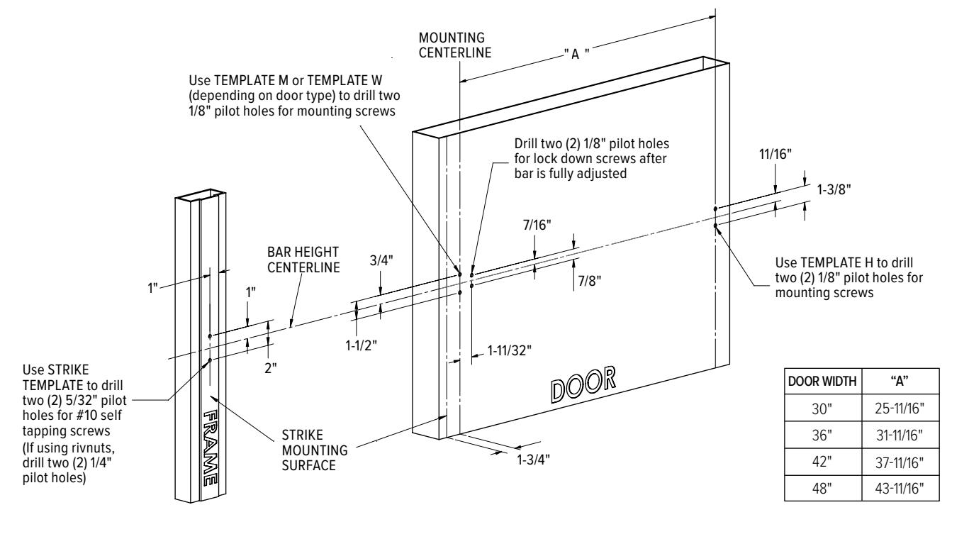
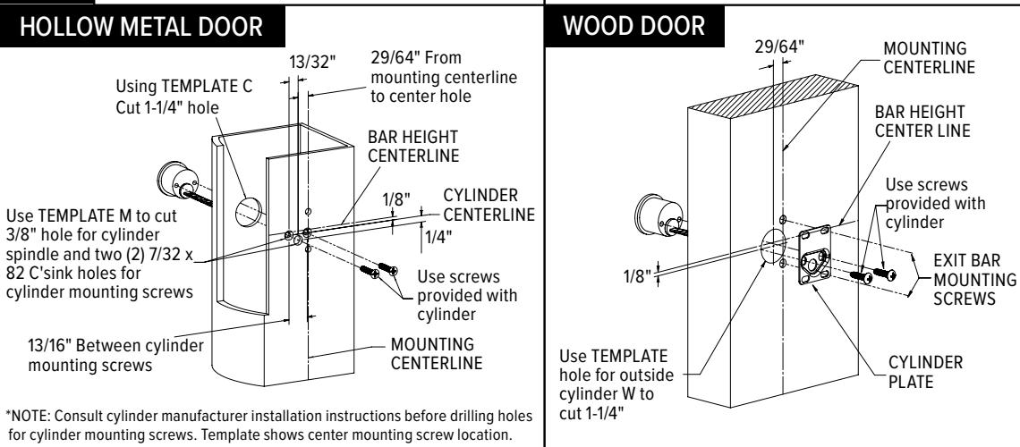
Determine bar height and use provided templates to drill pilot holes in door and frame. NOTE: If installing cylinder or trim, drill prep holes during this step as well. See 2b for details.
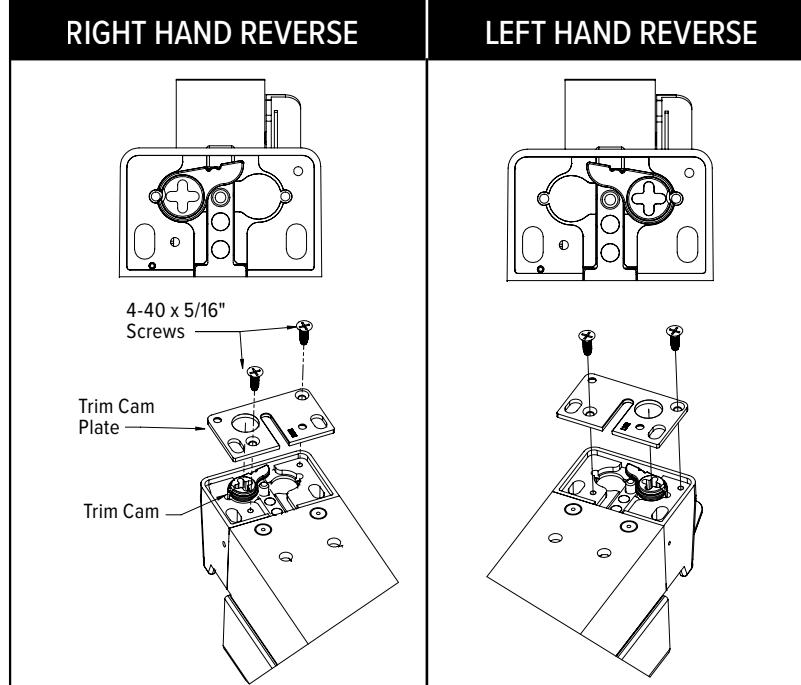
*SKIP STEPS 2a AND 2b IF NO OUTSIDE TRIM OR 2 a CYLINDER IS BEING INSTALLED
Install trim cam and trim cam plate on underside of exit bar as shown below. Ensure trim cam has proper engagement before installing bar onto door.
hole into outside surface of door then install cylinder.
Use TEMPLATE C to cut 1-1/4" Affix cylinder plate to cylinder. Ensure holes on plate align with holes for exit bar mounting screws.
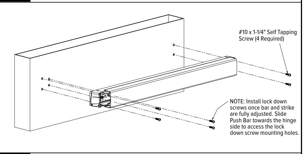
Install bar onto door frame using the provided #10 x 1-1/4" self tapping screws. Do not fully tighten screws until bar and strike have been properly adjusted.
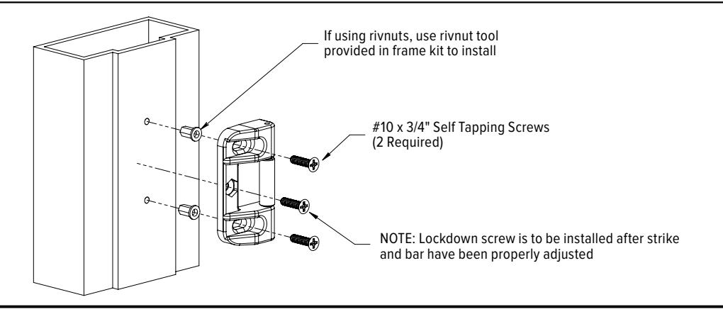
Install strike onto frame. Do not fully tighten screws until bar and strike have been properly adjusted.
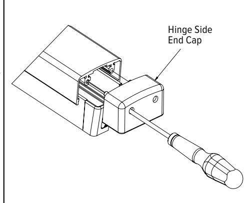
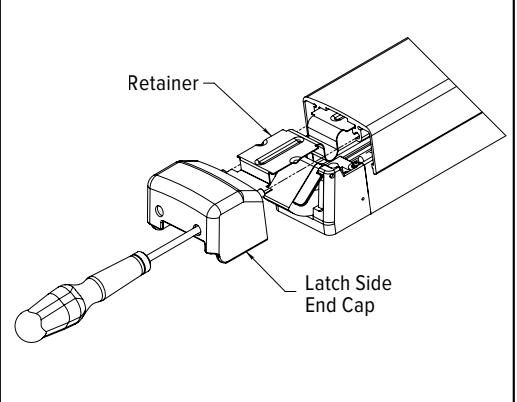
Use #2 Phillips head screw driver to install end caps. NOTE: screws are contained inside end cap assembly.
3