Adams Rite 8400 Exit Devices Installation Instructions
Open the original PDF document
View PDF

8400 Mortise Exit Device
Installation Instructions
Phoenix, AZ 85044 Tel: 1-800-872-3267
Mon-Fri: 6:00am - 4:00pm PDT
Fax: 1-800-232-7329
www.adamsrite.com
Preparing
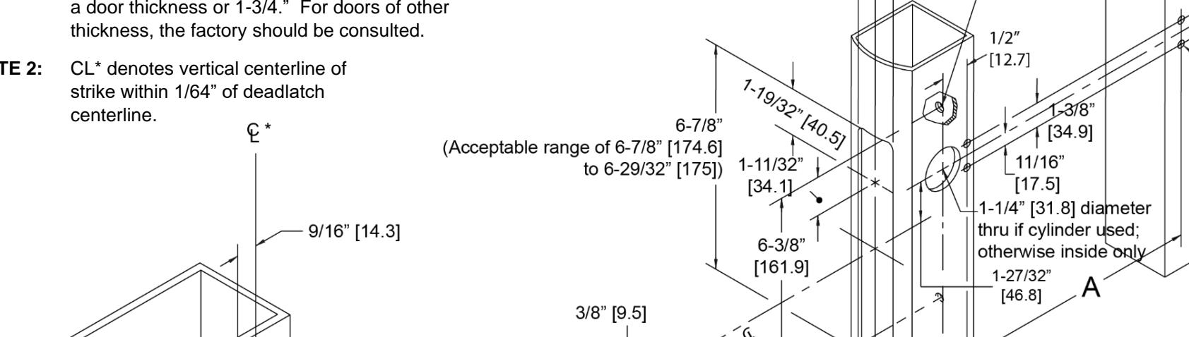
NOTE 1: These dimensions and templates assume a door thickness or 1-3/4." For doors of other
NOTE 2: CL* denotes vertical centerline of strike within 1/64" of deadlatch
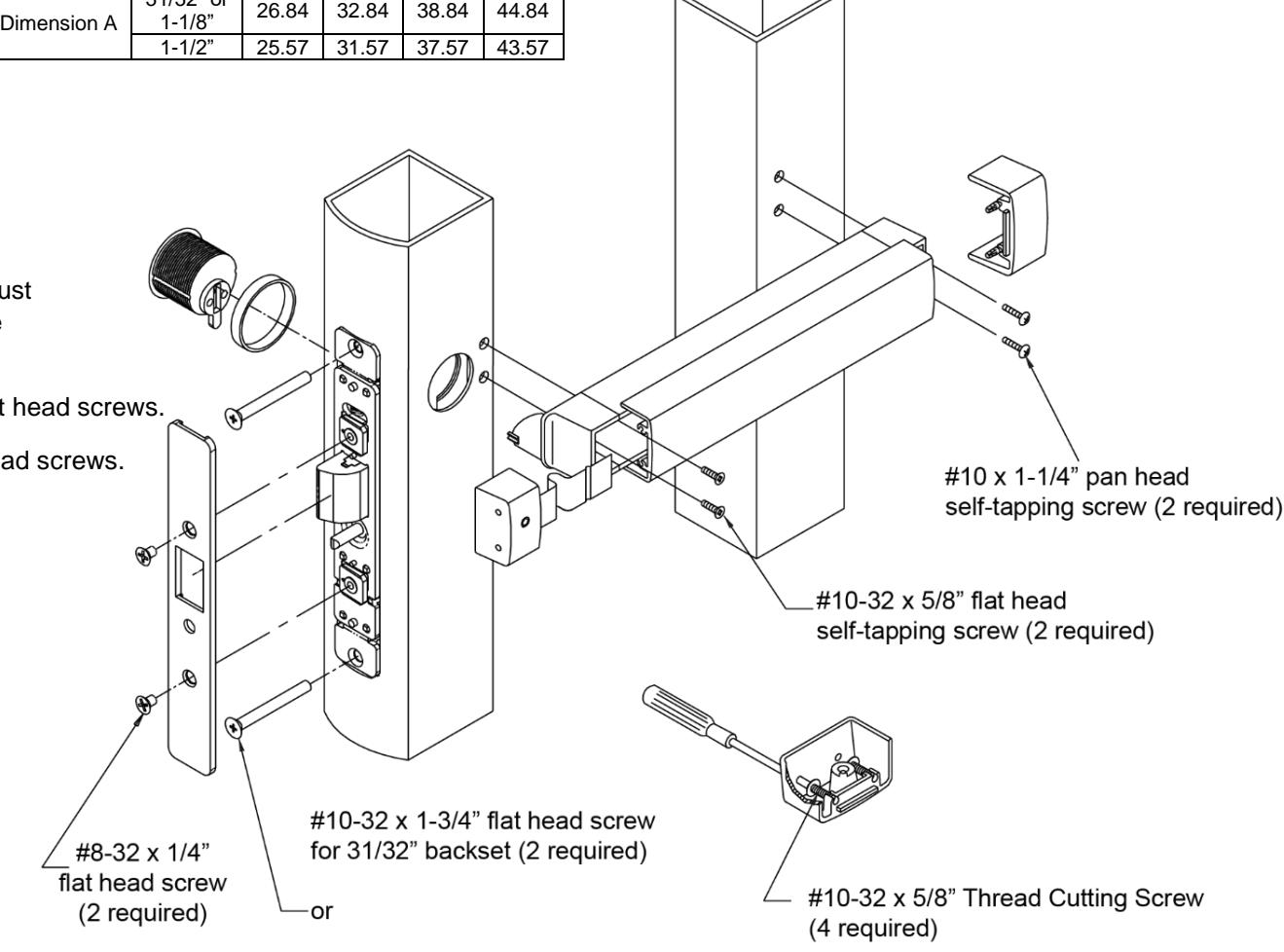
Mounting the Push Bar
1. DEPRESS latch bolt.
NOTE: The square key on plug must align with square notch on side plate.
- 2. INSERT bar assembly cam plug thru side plate.
- 3. INSTALL self-tapping screws on both ends and securely TIGHTEN.
- 4. TIGHTEN cam plug set screw.
- 5. INSTALL faceplate.
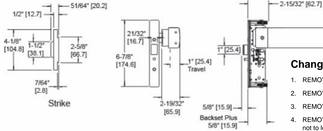
Backset Door Opening Width
31/32" or
30" 36" 42" 48"
6. INSTALL end caps (dogging socket at latch end).
Installing the Strike
NOTE: Both strike cup and strike plate must be installed properly to meet code requirements.
1. INSTALL cast strike cup with #10-32 flat head screws.
2. INSTALL strike plate with #10-32 flat head screws.
Installing the Deadlatch
- 1. ADJUST mounting post to length required to flush faceplate with nose of stile.
- 2. TIGHTEN lock case securely using #10-32 screws.
IMPORTANT NOTE
Installation must be in accordance to all applicable building and life safety codes.
Separating Push Bar and Mounting Bar
- 1. REMOVE both end caps (retainer is attached to nose end cap).
- 2. SLIDE push bar toward hinge side of door.
- 3. CONTINUE to slide push bar past the pivot plate that rides in push bar track.
- 4. SLIDE push bar in opposite direction, keeping pivot plate out of track until push bar is free of mounting bar.
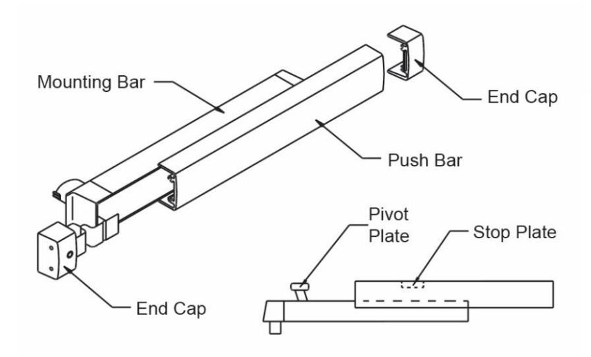
Installing Push Bar to Mounting Bar
- 1. With push bar in hand and mounting bar attached to door, FIND the stop plate staked into push bar (plate is on the latch end of the assembled unit).
- 2. SLIDE the pivot plate nearest the hinge into track of push bar until second pivot plate is exposed.
- 3. INSERT pivot plate into track on push bar and SLIDE in opposite direction until push bar and mounting bar align.
IMPORTANT NOTE
Installation must be in accordance to all applicable building and life safety codes.
Adams Rite is a brand associated with Hanchett Entry Systems, Inc., an ASSA ABLOY Group company. Copyright © 2016, Hanchett Entry Systems, Inc. All rights reserved. Reproduction in whole or in part without the express written permission of Hanchett Entry Systems, Inc. is prohibited.
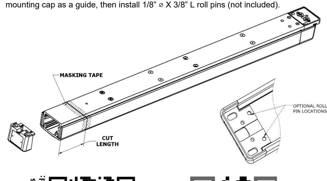
Bar Cutoff Instruction:
- 1. Remove push bar.
- 2. Tap mounting cap off hinge end of bar using a mallet or punch.
- 3. Re-install push bar, collapse, and tape down in area of cut-off.
- 4. Mark cut length on tape, see cutting guide on website for calculation.
- 5. Saw off excess, remove tape and deburr.
- 6. Tap mounting cap into bar using a soft mallet to protect finish.
- 7. Continue to installation instructions.
NOTE: Roll pin connection is optional; if desired, drill 1/8" holes thru bar using


Changing Hand of Exit Device
- 1. REMOVE screws and then spring retainer plate.
- 2. REMOVE two springs.
- 3. REMOVE auxiliary bolt.
- 4. REMOVE latch bolt and deadlocking arm assembly, being careful not to lose small internal spring.
- 5. REMOVE internal (deadlocking) spring.
- 6. SLIDE pin out of latch bolt and REMOVE deadlocking arm.
- 7. REPLACE deadlocking arm on opposite side of latch bolt and INSTALL pin.
- 8. INSTALL internal spring and INSERT latch bolt and deadlocking arm assembly into latch case.
- 9. INSTALL auxiliary bolt.
- 10. REPLACE two springs.
- 11. INSTALL spring retainer plate.
Exit Bar Front Back LHR Crank Cam (for easy removal. hold Cam stationary) RHR
Front View
- 1. REMOVE link from crank arm.
- ROTATE crank to opposite direction.
- CONTINUE moving crank arm as as bar is released.
Back View
- 1. REMOVE Cam screw.
- 2. FLIP Cam over to opposite position.
- 3. REPLACE Cam screw and TORQUE to 6.5-7.0 inch pounds.
2.375