Adams Rite 7111 Electric Strikes Wood Installation Instructions
Open the original PDF document
View PDF
PRODUCT MUST BE INSTALLED ACCORDING TO ALL APPLICABLE BUILDING AND LIFE SAFETY CODES
REF. TEMPLATE NO.: 52040-0
INSTALLATION INSTRUCTIONS
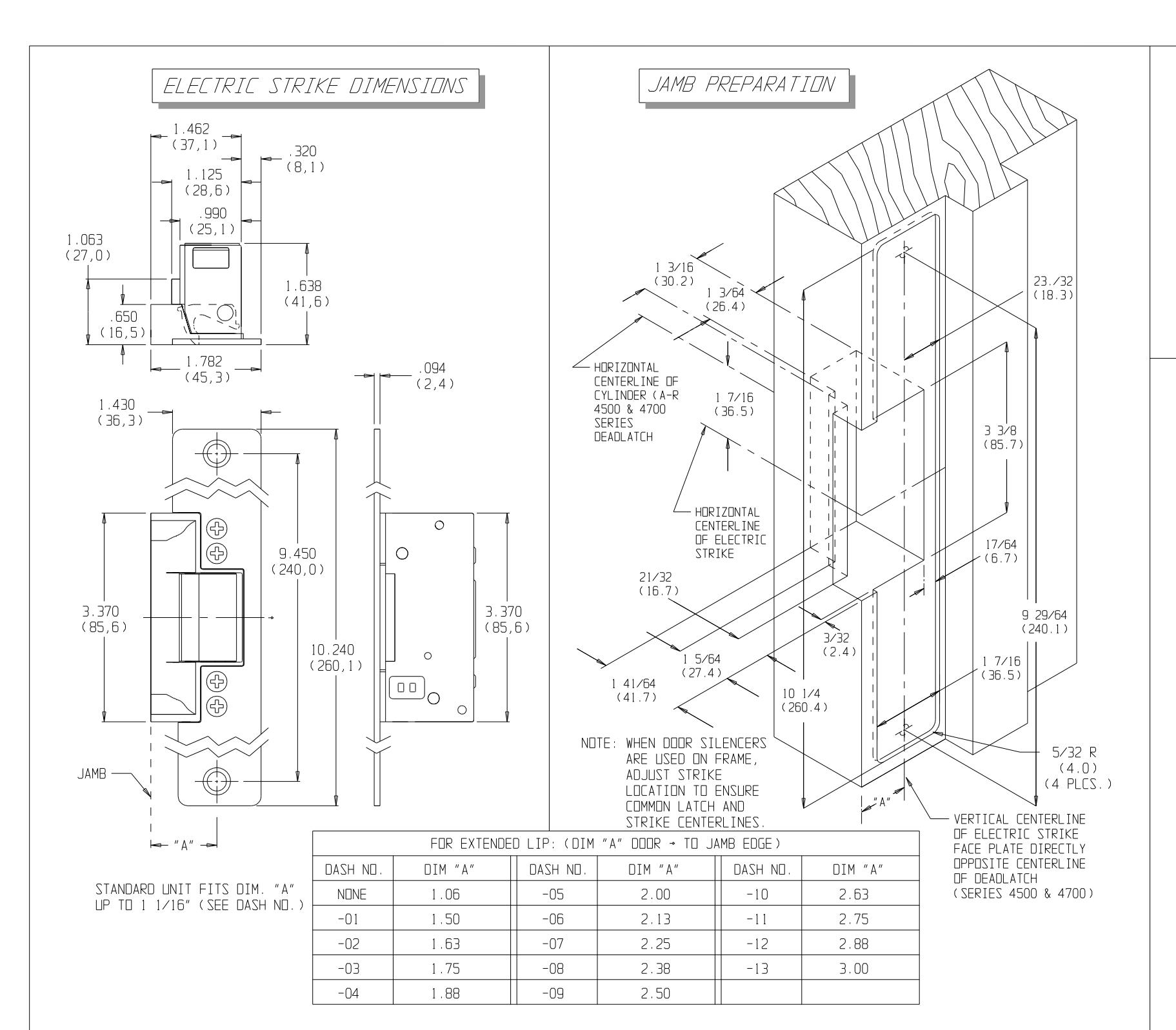
- 1. PREPARE DOOR JAMB PER DRAWING.
- 2. ATTACH SUBCOVER AND FACE PLATE TO THE CASE ASSEMBLY USING FOUR 8-32 X 1/4 SCREWS.
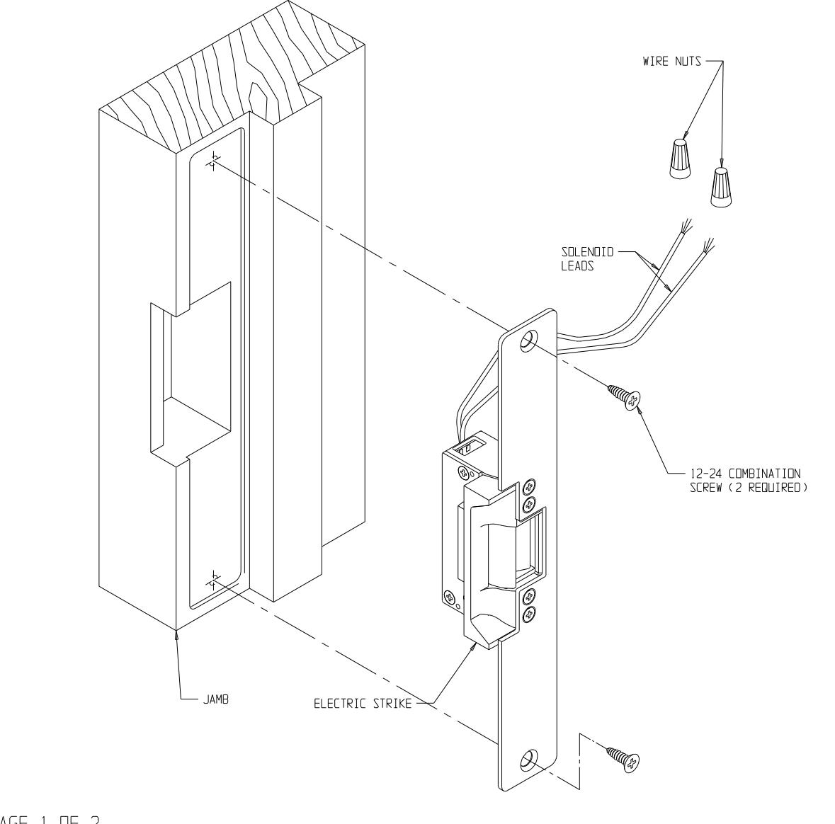
- 3. USING WIRE NUTS PROVIDED, CONNECT WIRES FROM SOLENDID TO THE WIRES COMING FROM THE LOW VOLTAGE SIDE OF THE TRANSFORMER.
- 4. INSERT ELECTRIC STRIKE INTO JAMB. ATTACH WITH TWO #12 COMBINATION SCREWS.
| STATIC STRENGTH | DYNAMIC STRENGTH | ENDURANCE | |
|---|---|---|---|
| 1500 lbs. | 70-foot-pound-force | 250,000 cycles | |
PAGE 1 DF 2
PAGE 2 DF 2 IS 80-0180-381 REV. H
www.adamsrite.com Phone: 80-0180-353
7111 ELECTRIC STRIKE FOR WOOD JAMB W/ AR 4500/4700/4900 DEADLATCHES
Fax: 866-582-4641 Rev. G
Ecn 11955B
Date: 06/28/12
Page 1 of 2
Appvd: MP
Date: 07/06/12
Notes:
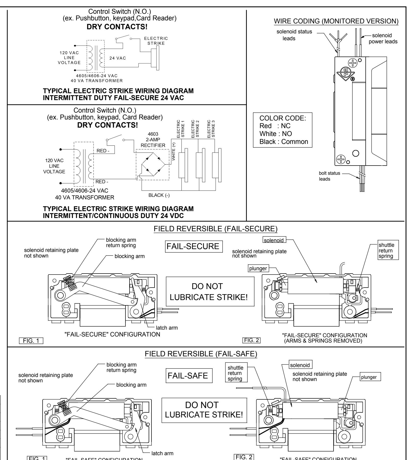
Fail-Secure Operation - Unlocks when energized. If power fails the strike remains in a locked condition.
Fail-Safe Operation - Locks when energized. Used in applications requiring automatic unlocking in case of power failure.
Available Voltages: 12V AC Intermittent duty, 12V AC/DC Continuous duty, 16V AC Intermittent duty, 16V AC/DC Continuous duty, 24V AC Intermittent duty, 24V AC/DC Continuous duty,
Warning!
AC Intermittent duty solenoids are designed to be energized 30 seconds at a time. Energizing for longer periods will damage the solenoid.
AC Continuous duty strikes are supplied with a A/R # 4603 rectifier attached to the solenoid leads. These are silent operation strikes - without the "buzzing" sound. They use a DC solenoid with an externally attached, full-wave bridge rectifier.
Wiring
The number of wires will vary depending on features of the strike. The voltage and amperage ratings are marked on all strike labels. The solenoid wires are not polarized.
Monitoring (Optional)
Monitored strikes contain two, internally mounted, switches: one is activated by the latch bolt's penetration of the strike and the other indicates that the strike jaw is either locked or unlocked by the solenoid.
All unused leads from monitor switches should be insulated.
Common contact -Black Normally open contact (NO) -White Normally closed contact (NC) -Red
Maximum switching current -7 Amps @ 250 VAC
Warning!
Intermittent duty solenoids should not be converted to fail-safe configuration. Fail-safe units use only continuous duty solenoids.
Solenoid Data
| 24 VDC CONT. | WHITE STRIPE ON BLACK | 141.6 | .170 | .170 | 4.09 | 4.09 |
| 16 VDC CONT. | GREEN STRIPE ON BLACK | 61.8 | .222 | .222 | 3.05 | 3.05 |
| 12 VDC CONT. | RED STRIPE ON BLACK | 34.6 | .332 | .332 | 3.81 | 3.81 |
| 24 VAC INT. | RED STRIFE ON BLACK | .744 | .431 | 19.15 | 6.43 | |
| 16 VAC INT. | BLUE STRIPE ON BLACK | 16.3 | 1.030 | .636 | 17.30 | 6.60 |
| 12 VAC INT. | YELLOW STRIPE ON BLACK | 8.8 | 1.420 | .813 | 17.74 | 5.82 |
| DESCRIPTION | WIRE COLOR |
COIL RESISTANCE
(OHMS ±5%) |
PEAK INSTANTANEOUS
CURRENT (AMPS) |
CONTINUOUS OR
HOLD CURRENT (AMPS) |
PEAK INSTANTANEOUS
POWER (WATTS) |
CONTINUOUS OR
HOLD POWER (WATTS) |
"FAIL-SAFE" CONFIGURATION (ARMS & SPRINGS REMOVED)

ASSA ABLOY
www.adamsrite.com Phone: 800-626-7590 800-872-3267
Fax: 866-582-4641
7100 SERIES (DATA SHEET WIRE CODING FIELD REVERSIBLE)
80-0180-381 Appvd: MP Date: 07/20/12 ECN: 11955D Date: 06/19/12 Rev. H Page 1 of 1
"FAIL-SAFE" CONFIGURATION