Adams Rite 4900 Deadlatches Installation Instructions
Open the original PDF document
View PDF

ASSA ABLOY
www.adamsrite.com Phone: 800-626-7590 800-872-3267
Fax: 866-582-4641
800-232-7329
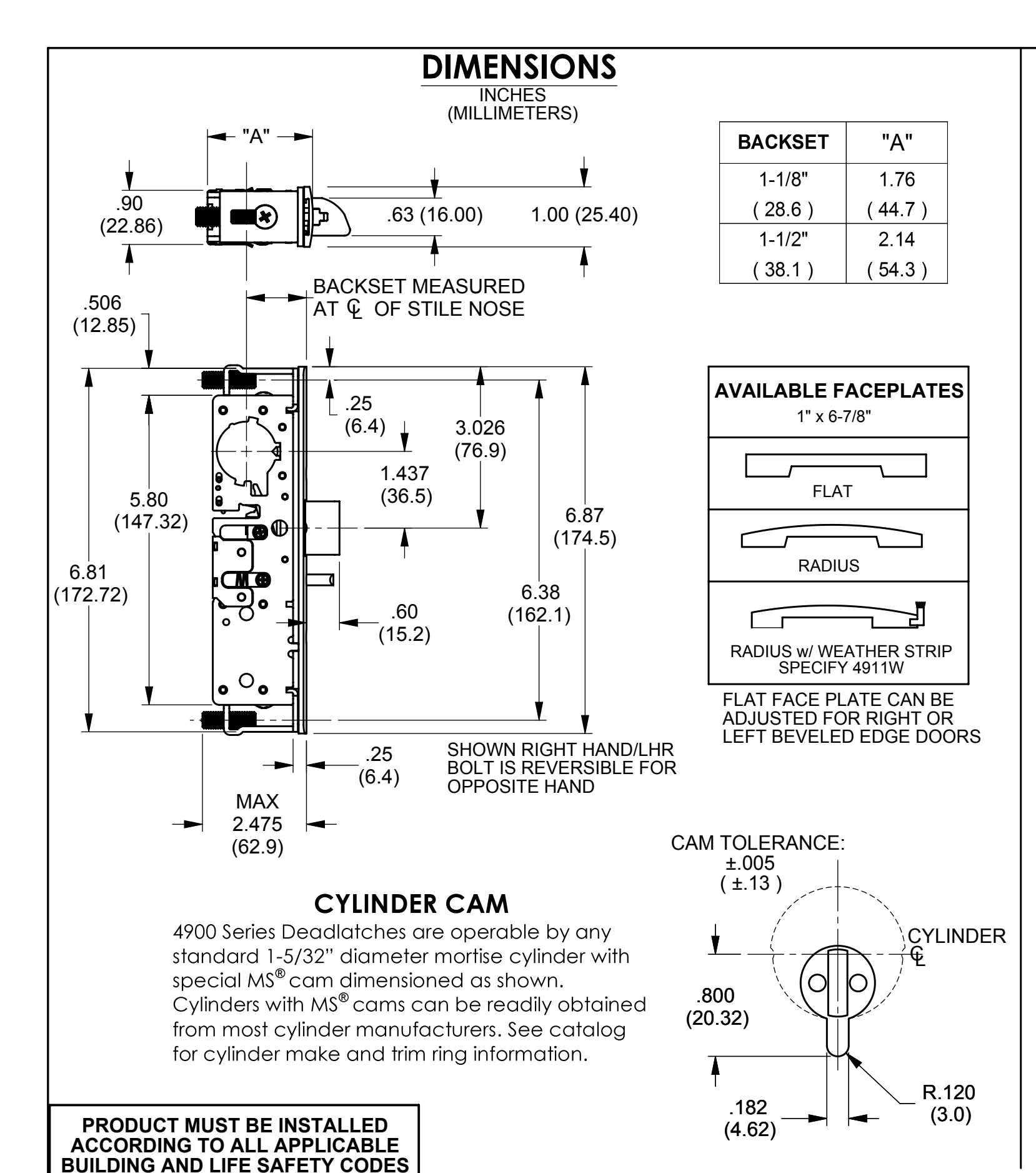
4900 SERIES DEADLATCH
80-0180-349
Rev. E
ECN: 11955B
Date: 06/28/12
INSTALLATION INSTRUCTIONS
Page 1 of 2 Appvd: MP Date: 07/06/12
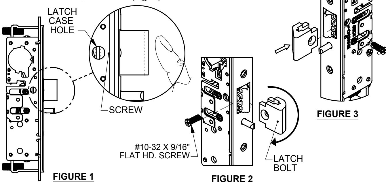
RE-HANDING
Depress latchbolt until #10-32 x 9/16" screw can be seen through the latch case hole (Fig. 1). Remove and rotate latch bolt to the opposite hand (Fig. 2). Depress latchbolt until the countersink screw hole on the latchbolt can be seen through the case hole. Insert and fasten #10-32 x 9/16" screw (Fig. 3).
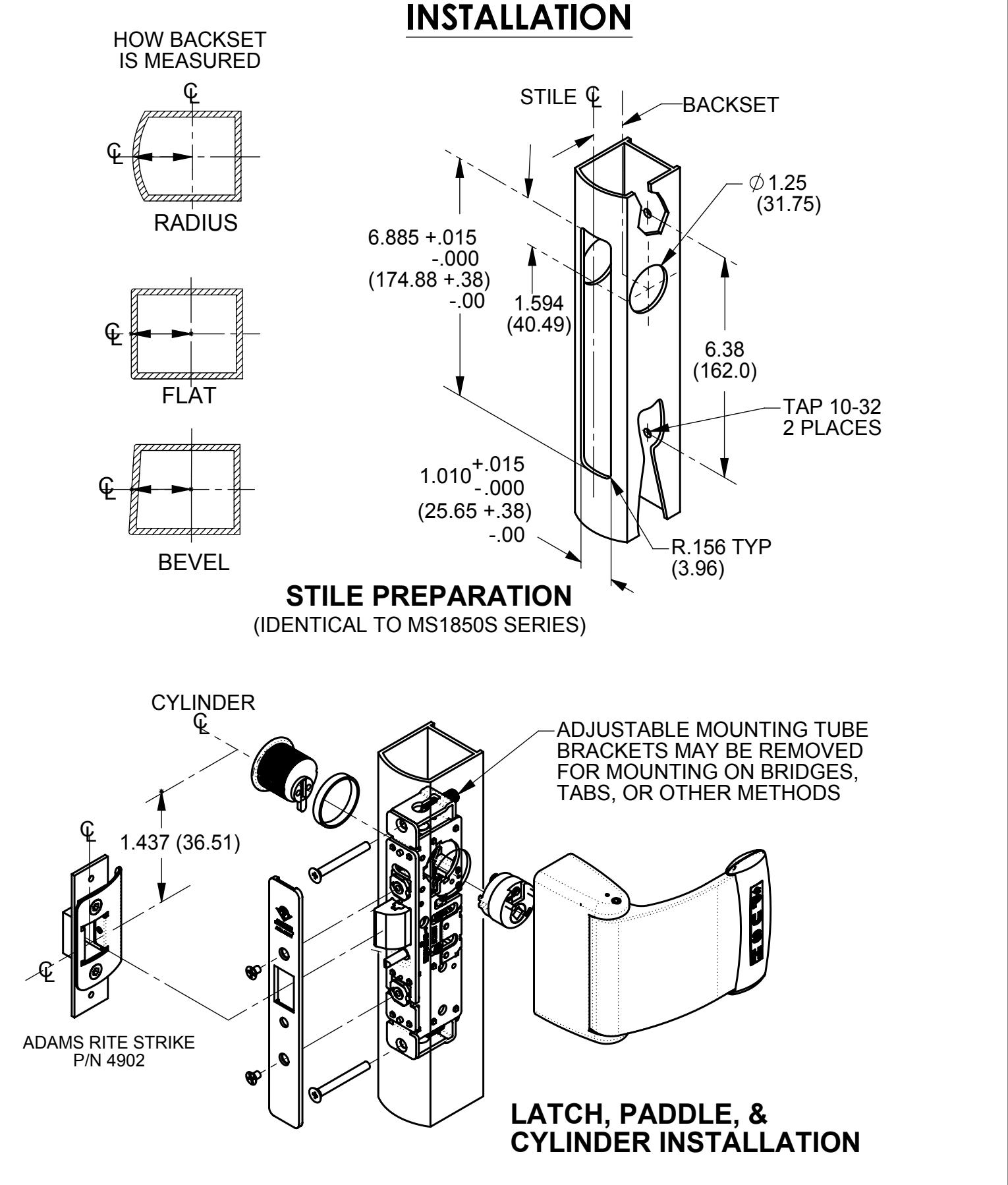
FOR MOUNTING TAB INSTALLATIONS
Remove top and bottom #8-32 x 5/16" truss hd. screw (Fig. 1) as shown. Remove yoke, and refasten " truss hd. screw (Fig. 2).
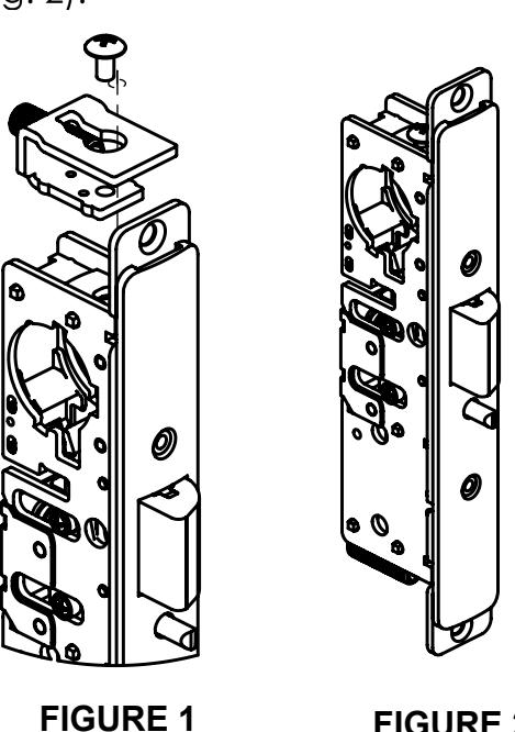
FIGURE 2
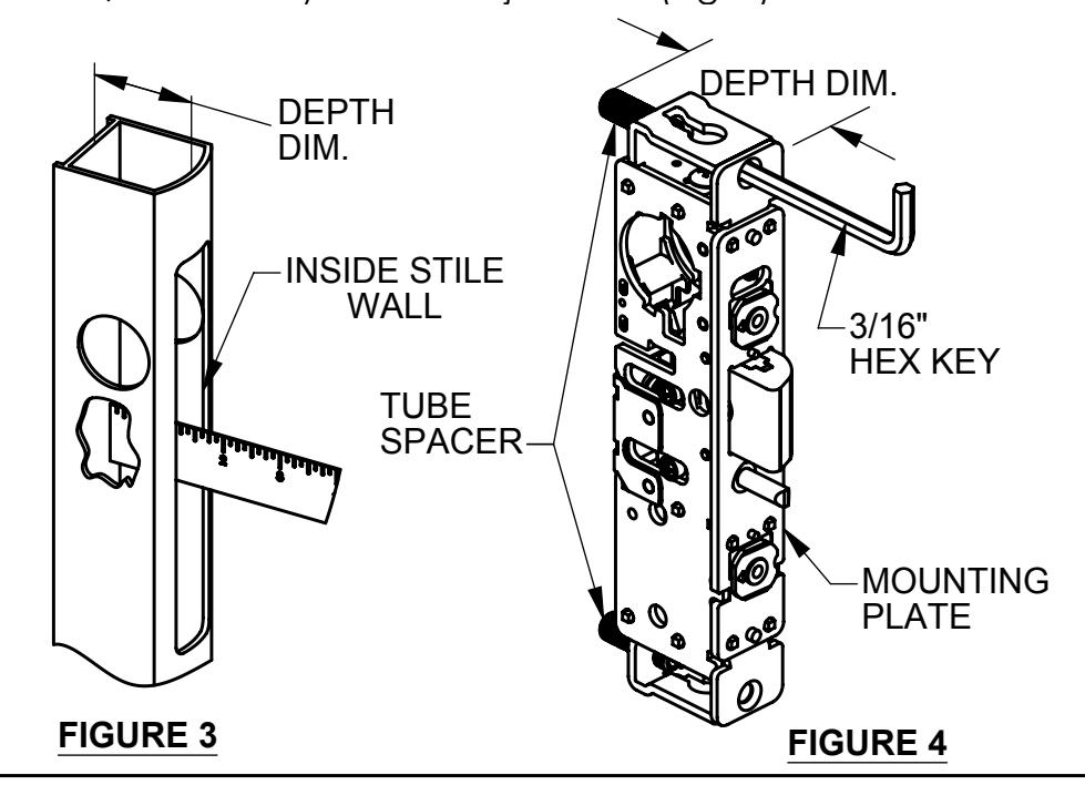
FOR TRADITIONAL MOUNTING INSTALLATIONS
Measure the depth from the back of the stile to the inside wall of door edge (Fig. 3). Match the distance from the face of mounting plate to end of tube spacer. Use 3/16" hex key for fine adjustment (Fig. 4).
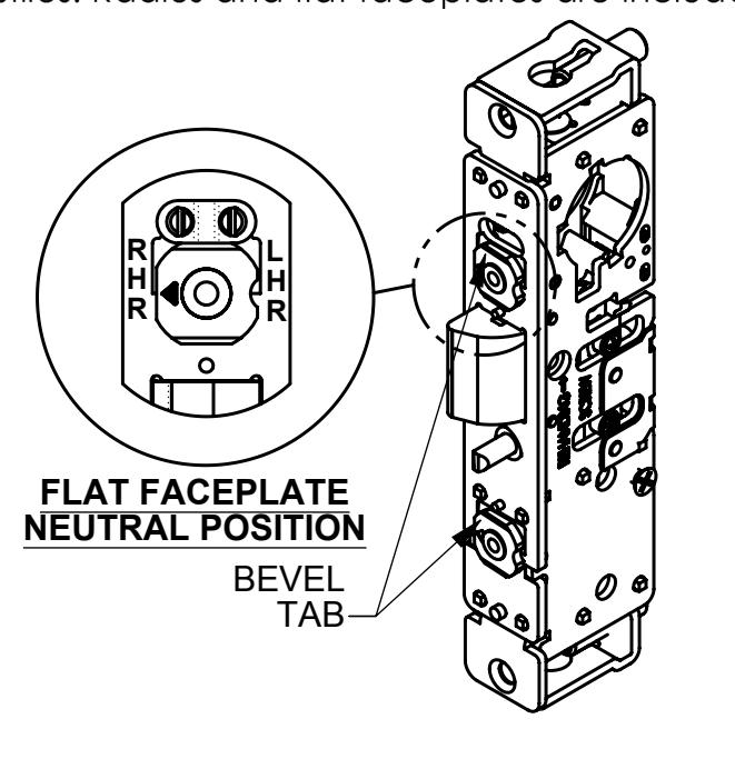
BEVEL ADJUSTMENT
Rotate bevel tab to desired hand. Using the bevel adjustment allows the flat faceplate to work in beveled stiles. Radius and flat faceplates are included.


LHR BEVEL POSITION
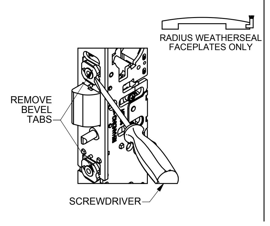
FOR RADIUS WITH WEATHERSEAL FACEPLATE ONLY
With a small screwdriver, remove bevel tabs as shown.
LATCH HOLDBACK
A reverse turn of the key (while bolt is held fully retracted) retains the bolt, allowing the door to be free swinging.
#6-32 x 3/16" SCREW
•
TO BLOCK HOLDBACK FEATURE
Install #6-32 x 3/16" screw into case as shown before installing in door.
PRODUCT MUST BE INSTALLED ACCORDING TO ALL APPLICABLE BUILDING AND LIFE SAFETY CODES
_____Adams Rite
ASSA ABLOY
www.adamsrite.com Phone: 800-626-7590 800-872-3267
Fax: 866-582-4641 800-232-7329
4900 SERIES DEADLATCH
INSTALLATION INSTRUCTIONS
80-0180-349
Rev. E
ECN: 11955B
Date: 06/28/12
Page 2 of 2 Appvd: MP Date: 07/06/12