Adams Rite 4550 Series Levers Installation Instructions
Open the original PDF document
View PDFSTEP 1
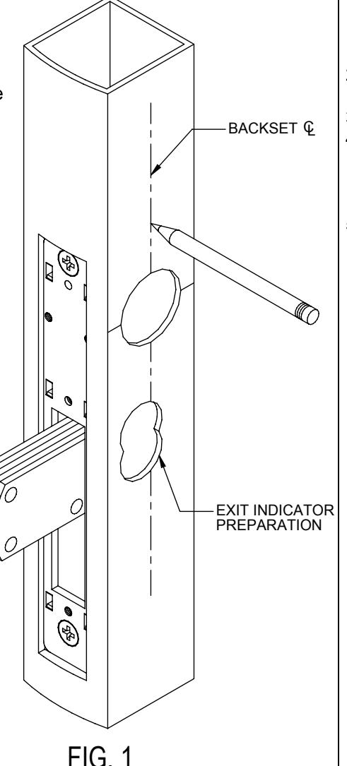
NOTE: Not compatible with 7/8" backset locks
STILE PREPARATION
- 1. Remove interior cylinder, thumbturn or exit indicator.
- Mark a backset centerline reference on the door stile approximately four inches above and below the existing cylinder hole.
- Tape clear plastic drilling template over cylinder hole and backset centerline reference.
- 4. Center punch the four mounting holes, drill and tap for #10-32 screws.
- 5. If not previously prepared for, center punch and drill two 7/8" holes for the exit indicator.
STEP 2
CAM ASSEMBLY INSTALLATION
- 1. Rotate the actuating hub so that the cam arms as shown in Fig. 2.
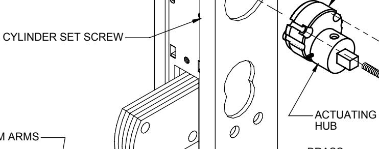
- 2. Insert the cam assembly into the lock case (fig. 3).
- 3. Tighten the cylinder set screw.
- 4. Install and tighten (snug only) the two #6-32 x 1/2" brass socket head cap screws to secure the Cam Assembly. Do Not Over Tighten!
- 5. Rotate the actuating hub to check operation.
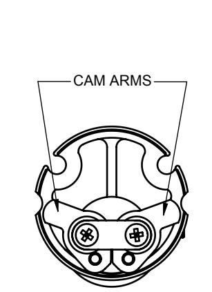
FIG. 2

CAM PLUG ASSEMBLY
Required Tools:
Phillips Screwdriver Flat Blade Screwdriver (Set Screw)
Pencil
Center Punch Hand Drill
5/32" Drill Bit
#10-32 Tap 7/8" Hole Saw
7/64" Allen Wrench
www.adamsrite.com Phone: 800-626-7590 800-872-3267
Fax: 866-582-4641 800-232-7329
4550 SERIES
80-0180-460
Rev. M
Ecn 11955D
INSTALLATION INSTRUCTIONS
FIG. 3
PAGE 1 OF 2
Date: 76/20/12
Appvd: MP

P
LEVER ASSEMBLY MOUNTING:
- 1. Rotate actuating hub until deadbolt extends and until it makes a complete stop. Then rotate the actuating hub back approximately ¼ turn until the hole is at the 12 o'clock position (as shown in fig.5).
- 2. Insert the Exit Indicator Spring in the lower hole of the bolt cutout.
- 3. Inside the Lever Assembly, slide the Exit Indicator so that "LOCKED" is displayed in
- 4. Place Lever Assembly onto the door, ensure the actuating hub spindle engages the Drive Hub (fig. 6) inside the Lever Assembly.
- 5. Secure the Lever Assembly with the four #10-32 x 3/4" phillips pan head screws.
- 6. Re-install faceplate.
OPERATION:
- 1 Turn the Lever downward 90° to unlock When released the Lever returns to the horizontal position.
- 2. Turn the Lever upward 90° to lock. The DEADBOLT must extend and remain extended when the lever is released.
- 3. Exit Indicator should correspond to deadbolt position.
ACTUATING HUB IN THE 12 O'CLOCK POSITION Lever may stick if the lever assembly is mis-located. LEVER ASSEMBLY loosen mounting screws and move B the assembly around to find the best location, then secure. #1 EXIT INDICATOR SPRING 1-55/64" FOR 2 AND 3 POINT SYSTEMS: FIG. 5 USE EXIT INDICATOR PIN AND #10-32 x 3/4" Phillips #2 EXIT INDICATOR SPRING 37/64" Pan Head Screws
REHANDING:
- 1. Remove the #10-32 x 7/16" phillips flat head machine screw from the spring retainer bushing. Remove the return spring and bushing.
- 2. Remove the four pan head machine screws holding the stop plate. Lift out the stop plate.
- 3. Turn the lever 1-1/2 ROTATIONS to reverse the lever position. Ensure the drive hub is alianed vertically as shown in FIG. 6.
- 4. Reinstall the stop plate, orient as shown in drawing. The open end of the stop plate should always face the handle. Secure the stop plate with the four machine screws
- 5. Place return spring around retainer bushing. With lever in the horizontal position, install with the inside bend of the bottom lea of the spring around the stand-off. Swing the top leg of the return spring over to the other side of the stand-off. See FIG. 7
- 6. Secure return spring bushing with the #10-32 x 7/16" phillips flat head machine screw.
Note: The Cam Assembly is Non-Handed.
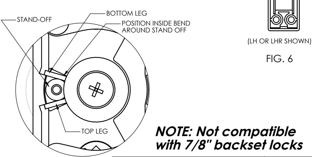
FIG. 7
| Replacement Parts Available | |
|---|---|
| Cam Plug Assembly kit (Clutched MS Lever) | 91-0752 |
| Handle Return Spring | 28-0019 |
| Return Spring Bushing | 26-0157 |
| Exit Indicator Spring - 1 3/4" Door | 28-0008 |
| Exit Indicator Spring (for 2 or 3 point Systems) - 1 3/4" Doo | 28-0008-01 |
| Exit Indicator Pin(for 2 or 3 point Systems) - 1 3/4" Door | 26-0455 |
| Stop Plate | 22-0656 |
| #6-32 x 5/16" Phillips Pan Head Screw (Stop Plate) | S222-06R05N603 |
| #10-32 x 7/16" Phillips Flat Head Screw (Spring Bushing) | S227-10R07N603 |
| #6-32 x 1/2" Socket Head Cap Screw (Cam Assembly) | S242BA06-08 |
PAN HFAD MACHINE
SCREWS-
SPRING
RETAINER
BUSHING .
#10-32 x 7/16" Phillips
Flat Head Mach, Screw
STOP PLATE
DRIVE HUB

www.adamsrite.com Phone: 800-626-7590 800-872-3267
Fax: 866-582-4641 800-232-7329
4550 SERIES
80-0180-460
Rev. M
INSTALLATION INSTRUCTIONS
Ecn 11955D PAGE 2 OF 2
Date: 07/20/12 Appvd: MP