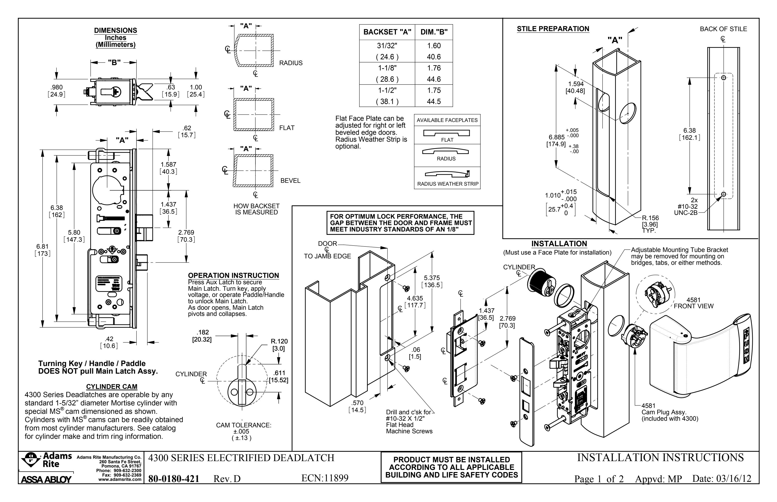
Adams Rite 4300 Deadlatches Installation Instructions
Open the original PDF document
View PDF
FOR TRADITIONAL MOUNTING INSTALLATIONS
- Measure the depth from the back of the stile to the inside wall of door edae (Fig. 1).
- Match the distance from the face of the Mounting Plate to the end of Tube Spacer. Use 3/16" Hex Key for fine adjustment (Fig. 2).
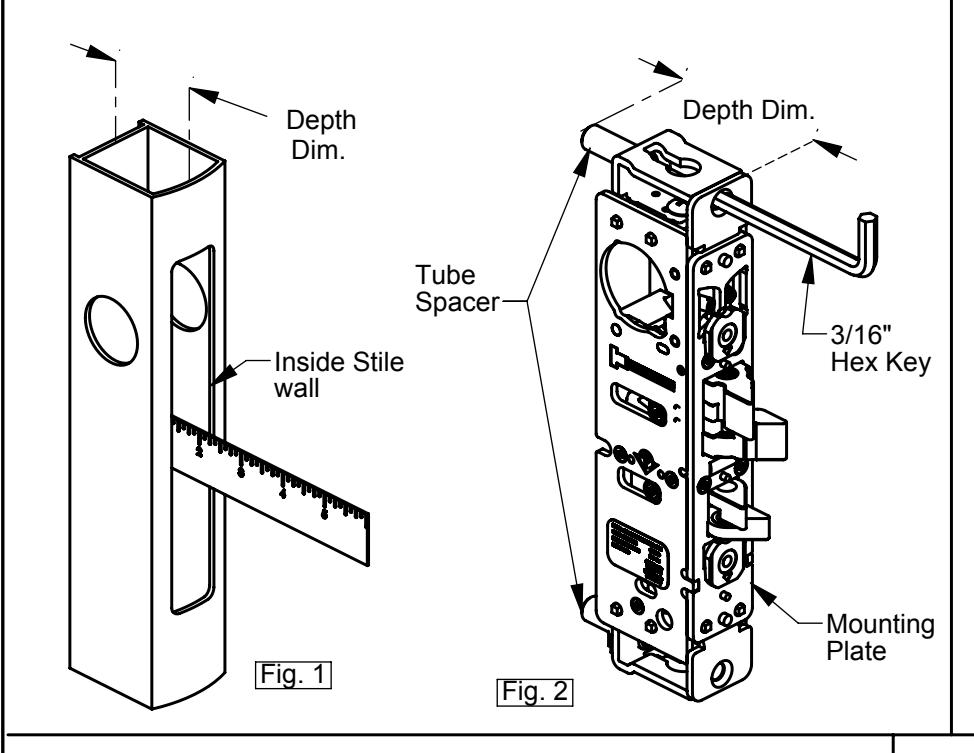
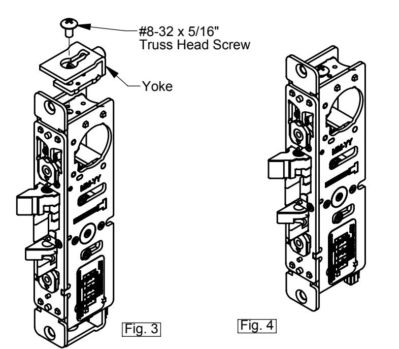
FOR MOUNTING TAB INSTALLATIONS
- Remove top and bottom #8-32 x 5/16" Truss Head Screw as shown (Fig. 3).
- Remove Yoke, and refasten #8-32 x 5/16" Truss Head Screw (Fig. 4).
BEVEL ADJUSTMENT
- Rotate Bevel Tab to desired hand (Fig. 5). Using the bevel adjustment allows the Flat Faceplate to work in beveled stiles. Radius and Flat Faceplates are included.
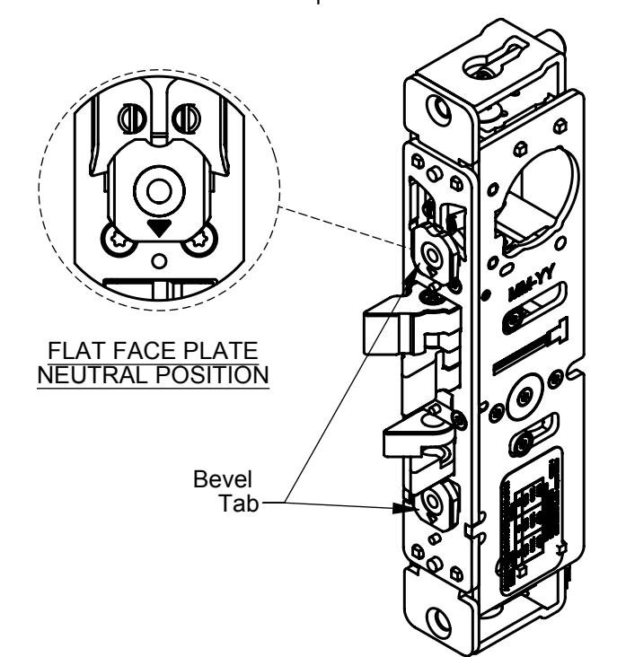
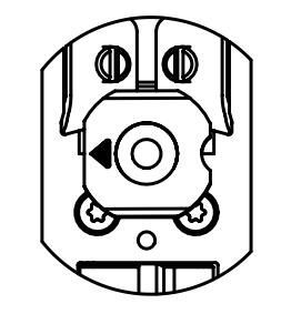
RHR BEVEL POSITION
Fig. 5
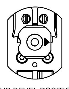
LHR BEVEL POSITION
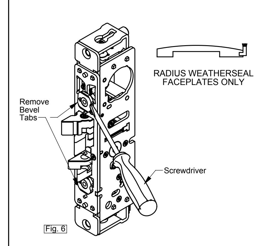
FOR RADIUS WITH WEATHERSEAL FACEPLATE ONLY
- With a small screwdriver, remove bevel tabs as shown (Fig. 6)
SOLENOID SPECIFICATION
SOLENOID AVAILABLE VOLTAGES 12V DC CONTINUOUS DUTY, 24V DC CONTINUOUS DUTY.
SOLENOID WIRING DIAGRAM
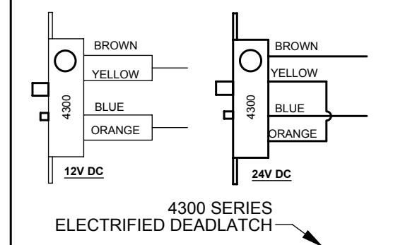
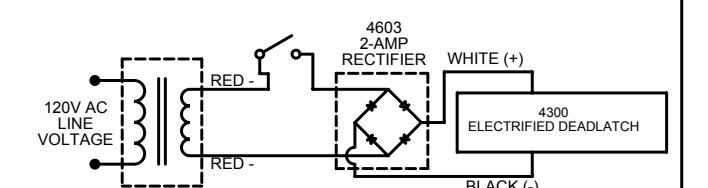
4300 WIRING DIAGRAM
INTERMITTENT / CONTINUOUS DUTY 12 / 24V DC
| VOLTAGE ADAPTOR CABLE | |||
|---|---|---|---|
| P/N# | WIRE COLOR | APPLICATION |
SOLENOID
CURRENT DRAW |
| VA7400-12 | BLACK | 12V DC | 0.44 AMPS |
| VA7400-24 | RED | 24V DC | 0.24 AMPS |
4605 / 4606 -24V AC
VOLTAGE
ADAPTOR CABLE
- LOOP THE WIRES BUNDLE FROM 4300 ELECTRIFIED 'S SOLENOID UNDER AND AROUND ITS HOUSING AS SHOWN (Fig.7)
- EXTEND THE WIRES RUN FROM THE POWER SOURCE AND THROUGH THE STILE PREPARATION
- CONNECT THE WIRE TO THE VOLTAGE ADAPTOR CABLE.
- ATTACH VOLTAGE ADAPTOR CABLE TO 4300 WIRES BUNDLE AS SHOWN.
MONITORING (OPTIONAL)
MONITORED DEADLATCH CONTAINS AN INTERNALLY MOUNTED SWITCH, THIS SWITCH IS ACTIVATED WHEN THE DOOR IS IN CLOSE POSITION. ALL UNUSED LEADS FROM THE MONITOR SWITCH MUST BE INSULATED.
Common contact Black Normally Open contact (N.O.) - White Normally Closed contact (N.C.) - Red
Maximum switching current - 0.1 Amps @ 125 VAC
EXAMPLE WIRING DIAGRAM WITH N.O. MONITORING
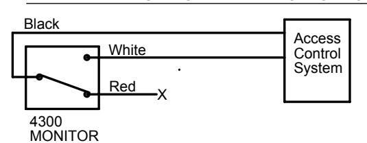
Black = Common White = N.O. contact (Dry) Red = N.C. contact (Dry) Unused wires must be cut such that no exposed wire will touch any metallic surface
Note: NOT intend to be a Rex switch.
ASSA ABLOY
Adams Rite Manufacturing Co. 260 Santa Fe Street, Pomona, CA 91767 Fax: 909-632-2369
www.adamsrite.com
4300 SERIES ELECTRIFIED DEADLATCH
Fig. 7
WIRES
BUNDLE
80-0180-421 Rev. D
ECN: 11899
PRODUCT MUST BE INSTALLED ACCORDING TO ALL APPLICABLE BUILDING AND LIFE SAFETY CODES
INSTALLATION INSTRUCTIONS
Page 2 of 2 Appvd: MP Date: 03/16/12