ASSA ABLOY SML980S CR908KMSM KRM200SM Split Mullion Installation Instructions_MEMN26
Open the original PDF document
View PDFSML980S / CR908KMSM / KRM200SM
Split Mullions
- Measuring Tape Pencil Hammer Center Punch #3 Phillips Screwdriver
- Drill & Tap Sizes: #7 drill and 1/4"-20 tap Concrete Drill: 3/8" diameter
-
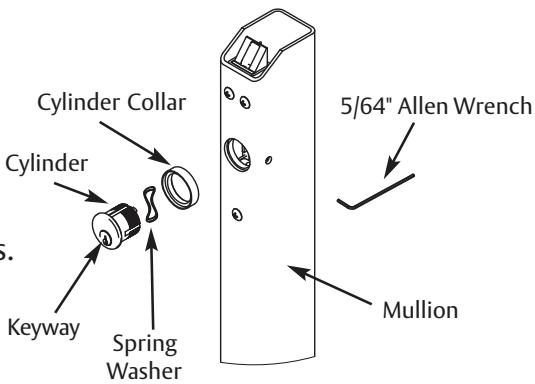
5/64" Allen Wrench 1/8" Allen Wrench
- 5/32" Allen Wrench
To install Mullion in frame
- 1. Close and block the doors against the frame stops. Check gap between door leaves and door to frame, and correct if necessary.
- 2. Locate the center of the opening on the floor. Using the bottom retainer, mark the positions for the two drop-in fasteners.
- a. The bottom of the door should come to rest against the surface of the mullion.
- b. Modify threshold as required.
- 3. Drill (2) 3/8" diameter holes in floor with cement bit to a minimum depth of 2-1/2".
- 4. Fasten bottom retainer to floor.
- 5. Locate the center of the opening on the top of the frame. Using the top retainer, mark the positions for the (4) fasteners.
- a. The door should evenly rest against both the frame stop and the mullion.
- b. If a top retainer mounting kit is used, modify weather-stripping as required.
- 6. Drill and tap each location for 1/4"-20 fasteners.
- 7. Mount top retainer on frame with provided fasteners.
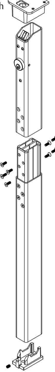
- 8. Assemble long mullion tube to connector using 8 1/4"-20 flat head screws (torque to 150in-lb)
NOTE: Short mullion tube goes on top.
9. Measure distance ("Dim X") between top of frame (where top retainer is mounted) and floor. Remove material from bottom of long mullion tube per the formula: Length of Assembled Split Mullion Tube = "Dim X" minus 3/4".
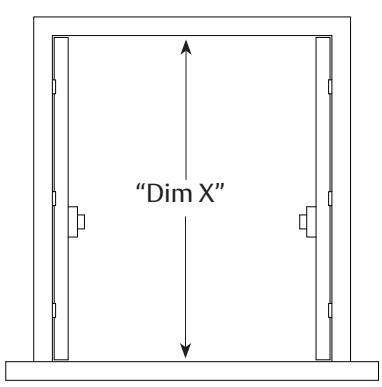
NOTE: This leaves approximately 1/8" clearance between the mullion and the top retainer when mounted.
MEMN26 8/23

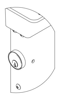
- 10. Installation of Cylinder
- a. Depress latchbolt and hold fully retracted.
- b. Carefully thread cylinder with cylinder collar and spring washer into lock assembly until it bottoms out.
- c. Unscrew the cylinder orienting keyway at bottom.
- d. Release latch bolt. Note: If latch bolt is not fully projected l oosen cylinder an additional 1-2 full turns.
- e. Tighten set screw with 5/64" allen wrench through access hole in side of mullion.
- f. Check operation of cylinder and lock assembly.

- 11. Place mullion onto bottom retainer and pivot into opening to latch.
- 12. Tighten bottom retainer set screw to prevent mullion rattle.
- 13. Install exit devices according to manufacturer's instructions.

This product can expose you to lead which is known to the state of California to cause cancer and birth defects or other reproductive harm. For more information go to www.P65warnings.ca.gov.