ASSA ABLOY Lock Configuration Tool User Manual_SWMN22A
Open the original PDF document
View PDF

Lock Configuration Tool
User Manual
Software Version 4.5

Experience a safer and more open world
Table of Contents
| 1. | Overview | 1 | |
|---|---|---|---|
| 1.1 | Hardware Requirements | 1 | |
| 1.2 | General System Information Requirements | 1 | |
| 1.3 | Menu Bar | 2 | |
| 1.4 | Navigating the Software | 3 | |
| 1.5 | Exit LCT | 3 | |
| 2. | Quick Start | 4 | |
| 2.1 | Create New Configuration File | 4 | |
| 2.2 | Create Lock Profile | 4 | |
| 2.3 | Open Existing Configuration File | 4 | |
| 2.4 | Configuration | 5 | |
| 2.5 | Diagnostics | 5 | |
| 3. | LCT Configuration File | 6 | |
| 3.1 | Create New Configuration File | 6 | |
| 3.2 | Open Existing Configuration File | 6 | |
| 4. | Profile | 7 | |
| 4.1 | Create New Profile | 7 | |
| 4. | 1.1 Lock Tab | 7 | |
| 4. | 1.2 Network Tab | 8 | |
| 4. | 1.3 Reader Tab | 10 | |
| 4. | 1.4 Pre-Deployment Operation Tab | 11 | |
| 4.2 | Copy a Profile | 12 | |
| 4.3 | Edit a Profile | 12 | |
| 4.4 | View a Profile | 12 | |
| 4.5 | Delete a Profile | 12 | |

| 5. | Configuration13 | ||
|---|---|---|---|
| 5.1 | Configuring a Lock | 13 | |
| 5.2 | Removing Lock from Previously Configured (History) | 17 | |
| 6. | Diagnostics18 | ||
| 6.1 | Power Test | 18 | |
| 6.2 |
Lock Switch State
|
18 | |
| 6.3 | Read Alarms | 19 | |
| 6.4 |
Get Reader Version
|
19 | |
| 6.5 |
Get Support Logs
|
19 | |
| 6.6 | NVRAM Reset | 20 | |
| 6.7 | Network Device Info | 20 | |
| 6.8 | Exiting Diagnostics | 20 | |
| 7. |
LCT Users
21 |
||
| 7.1 | Roles and Responsibilities | 21 | |

This Page Intentionally Left Blank.

1. Overview
The Lock Configuration Tool (LCT) software is used to configure locks with electronic access control.
This manual provides a Quick Start section that provides basic instructions on how to start the LCT software, create or open a configuration file, create and edit lock profiles, and run system diagnostics. More detailed information about the functions and screens are covered in other sections of this manual.
1.1 Hardware Requirements
The following items are required to use the LCT application. Please ensure all of these items are available before using the software.
- Laptop computer or other appropriate device (such as tablets that can use Windows OS) with minimum of Windows 10 OS and a USB 2.0 or higher port
- LCT application downloaded and installed on the laptop/device (see https://go.intelligentopenings.com/lct to download the application)
-
Appropriate USB cable with mini USB-B Male connector to connect the lock to the laptop/ device
- USB 2.0 to mini USB-B Male cable (Part Number: 10UM-02110BK) USB-C to mini USB-B Male cable OR USB 2.0 to USB-C adapter if laptop only has USB-C port
- Lock connected to the laptop/device with the USB cable
1.2 General System Information Requirements
The following items are necessary to configure the locks in the system.
- DHCP or Static IP Address information
- WiFi Connection Details, if applicable (SSID/Security Type/Key(AES) obtained from IT department or site representative)
- DSR/EAC System Connection Information
- Reader Configuration information (credential types to be used)
- Advanced Reader Configuration Items (Special Reader File)

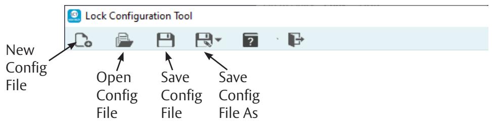
1.3 Menu Bar
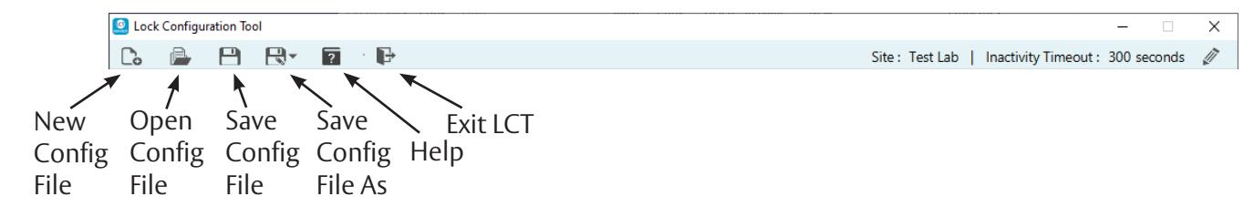
The Menu Bar located at the top of LCT screen contains command buttons for creating a new configuration file, opening an existing configuration file, saving the current configuration file, saving the current configuration file as encrypted text, help, and exit application.
The Help menu includes two options:
About
The About information box displays the software version number and date. Click the OK button to close the About information box.
User Manual
The User Manual command displays this manual.
The right side of the menu bar displays the Site Name and the Inactivity Timeout value, in seconds. The default is 300 seconds. To edit the Site Name and Inactivity Timeout settings, click the Edit button. The Edit General Information dialog box appears.

A Site Name is mandatory. Add or edit the site name in the Site text box. Enter or change the value (in seconds) for the Inactivity Timeout . Entering 0 (zero) turns off the inactivity timeout feature. Select the Automatically Save checkbox to turn on the automatic save feature. Click the Save button to save the changes. Click the Cancel button to discard the changes.
The Inactivity Timeout is the amount of time the LCT software has no activity. The application automatically exits and all changes are lost. The value must be between 0 and 99999 seconds.

1.4 Navigating the Software
All of the software screens are arranged in a tab structure. Click a tab to access the screen. The screens may have a subset of tabs contained within it. The main screen tabs are:
- Profile (Section 4 on page 7)
- Configuration (Section 5 on page 13)
- Diagnostics (Section 6 on page 18)
- LCT Users (Section 7 on page 21 )
To increase the screen size, hold the Ctrl key and press the Up Arrow key. To decrease the screen size, hold the Ctrl key and press the Down Arrow key.

Profile Tab Sub-Tabs
1.5 Exit LCT
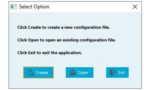
To exit LCT press the Exit button either from the menu bar or from the Select Option pop-up.
If any changes are pending a Confirm Action dialog box appears. Press the OK button to exit LCT without saving changes. Press the Cancel button to stop the exit process so changes can be saved using the Save or Save As buttons.

2. Quick Start
Ensure the requirements in Section 1 are met and then launch the LCT application. If this is the first time the application is being run to set up a system, follow the instructions in Sections 2.1 and 2.2. If a configuration file already exists, follow the instructions in Section 2.3.
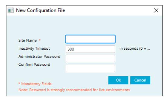
2.1 Create New Configuration File
When the application starts, click the Create button in the Select Option pop-up. The New Configuration File dialog box appears.
Type in the Site Name, Administrator Password, and Confirm the Password. Click the OK button to create the configuration file.
NOTE: It is highly recommended that a strong password is used for the system.
See Section "3. LCT Configuration File" for more details.
2.2 Create Lock Profile
- 1. Click the Profile tab. In the Lock tab type in a profile name, profile description (optional) and set the other settings as desired.
- 2. Click the Network tab. Select the device type(s) for the profile. Enter the IP address/Host Name (as applicable) and Port number. Select Static or DHCP for the Lock IP Settings.
- 3. Enter the appropriate WiFi information in the WiFi Manager section. Select/enter the appropriate information in the Lock Protocol Encryption section if applicable. Select the checkbox in the Custom Network Settings if applicable.
- 4. Click the Reader tab. Select the credential types to be used in the system, with the primary type set in row 0.
- 5. Click the Pre-Deployment Operation tab. Select the desired Alarm-Triggered and Scheduled Communication settings. Add temporary users if needed. Predominantly used to configure the locks to work without an EAC system during construction and testing phase.
- 6. When finished entering information in the four Profile tabs, click the Save button in the lower right corner of the screen.
See Section "4. Profile" for more details.
2.3 Open Existing Configuration File
When the application starts, click the Open button in the Select Option pop-up. The Open Configuration File dialog box appears.
- 1. Type in or Browse to select the configuration file (.exml).
- 2. Select the Username from the dropdown list.
- 3. Enter the password for the selected username.
- 4. Click the Open button to open the selected configuration file.

2.4 Configuration
Once the profiles are created, locks can be configured. To access the configuration screen, click the Configuration tab and then click the Action button next to the lock name.

The following are provided in the Configuration screen:
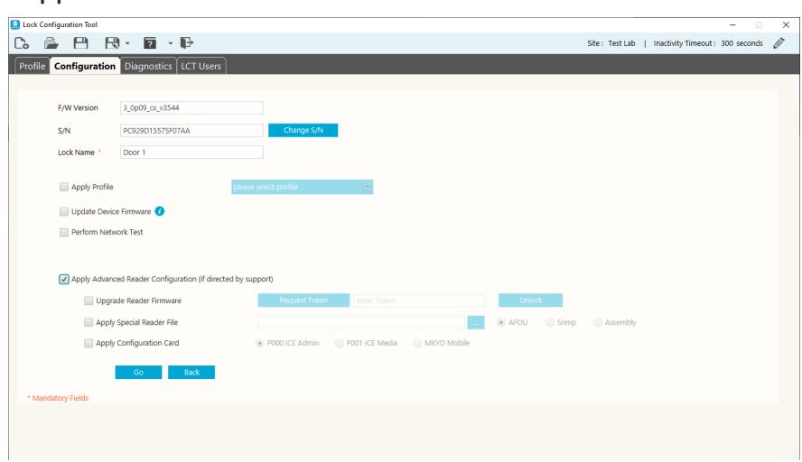
- F/W version current firmware version
- S/N Lock Serial Number click the Change S/N button to change the lock serial number.
- Lock Name name of lock (mandatory field)
The checkboxes are used to select configuration activities. When the desired activities are selected, click the Go button at the bottom of the screen.
- Apply profile used to apply a profile to the lock. Select a profile using the dropdown list.
- Update Device Firmware used to download and install the most recent firmware for the lock.
- Perform Network Test
- Apply Advanced Reader Configuration use this only if directed by Technical Support.
See Section "5. Configuration" for more details.
2.5 Diagnostics
- Click the Power Test button to display the relevant voltages for the lock.
- Click the Lock Switch State button to display the current Door Position Switch state and Lever Turned state.
- Click the Read Alarms button to display the alarm settings for the lock.
- Click the Get Reader Version button to display the current reader firmware version for the lock.
-
Click the
Get Support Logs
button to select the log type and specify a location to save the log files.
- The log types are NVRAM Image and Usage Logs. The Save Location is displayed for the selected log type.
- Click the NVRAM Rest button to perform an NVRAM reset.
- Click the Network Device Info button to view the current network information for the selected lock.
See Section "6. Diagnostics" for more details.

Experience a safer and more open world
3. LCT Configuration File
3.1 Create New Configuration File
To create a new configuration file, click the New Configuration File button in the main menu bar, or the Create button from the Select Option pop-up when the application is launched.
The New Configuration File dialog box appears.
Type in the Site Name, the number of seconds for the Inactivity Timeout, Administrator Password, and Confirm the Password. Click the OK button to create the configuration file.
NOTE: It is highly recommended that a strong password is used for the system.
NOTE: Inactivity Timeout must be between 0 and 99999 seconds.
3.2 Open Existing Configuration File
To open an existing configuration file, click the Open Configuration Fil e button from the main menu bar or the Open button from the Select Option pop-up when the application is launched. The Open Configuration File dialog box appears.
The software defaults to the last configuration file opened.
- 1. Click the Brows e button to select a different configuration file than the default file listed.
- 2. Select the desired username and enter the password for that username.
- 3. Click the Open button to open the configuration file.
- 4. Click the Cancel button to end the process without opening a configuration file.
| Open Conf | iguration File | × | ||
| File * | C\Users\|)\Desktop\Test Lab.exml | Browse | ı | |
| Username * | ADMINISTRATOR | _ | ||
| Password | ||||
| * Mandatory F | ields | Open | Cancel |

4. Profile
A lock profile consists of common configuration items that would apply to a group of locks. These configuration items include things like network configuration, reader configuration, and temporary users.
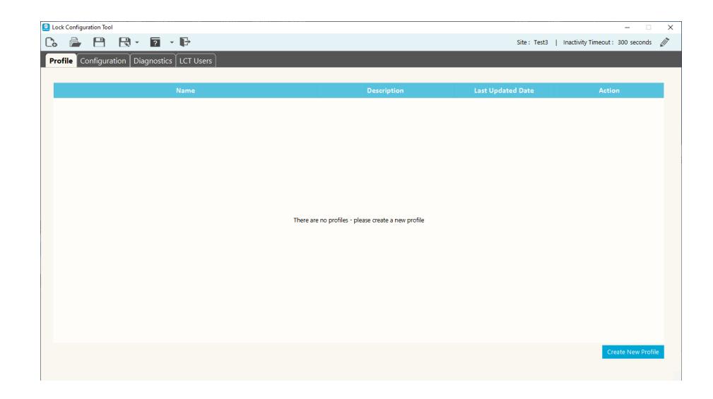
4.1 Create New Profile
To create a new lock profile, click the Create New Profile button.
4.1.1 Lock Tab
In the Lock tab, enter the following information:
Profile Name Enter a meaningful profile name (mandatory).
Profile Description Enter the profile description (optional). The profile description allows for a
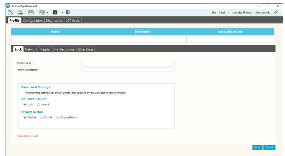
detailed description of the profile.

Basic Local Settings
These settings remain as set unless updated by the DSR/access control system:
• On Power Failure
The lock can be configured to automatically lock or unlock on power failure. Select Lock or Unlock.
• Privacy
Locks can be configured to support the use of the Privacy button. Select Disable, Enable, or Escape/Return.
4.1.2 Network Tab
In the Network tab, enter the following information:
Select the device type(s) being used with this profile: Wireless (WiFi) or Power over Ethernet (PoE). The check boxes filter the view to display only applicable fields for a specific device type or both boxes can be selected, if necessary.
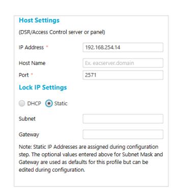
Host Settings
- IP Address: Enter the appropriate IP address.
- Host Name: Enter the host name.
- Port: Enter the port number that the lock uses
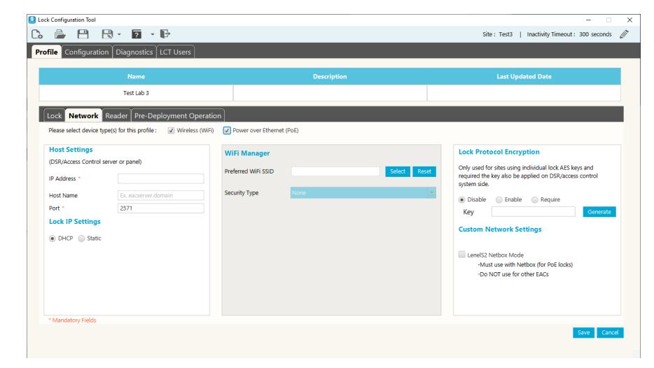
to communicate with the EAC system (default =2571).
NOTE: The Host settings pertain to the Door Service Router (DSR) server / Electronic Access Control (EAC) server or panel responsible for the locks configured with this profile. LCT will not allow the profile to be saved without the required information.
Required Host Settings fields are based on the selected device types: WiFi only: IP Address or Host Name (at least one) and Port PoE only or WiFi and PoE: IP Address and Port

Lock IP Settings
- DHCP
- Static
NOTE: Static IP Addresses are assigned during the configuration step. The optional values entered above for Subnet Mask and Gateway are used as defaults for this profile but can be edited during configuration step.
WiFi Manager
• Preferred WiFi SSID:
Click the Select button to display a list of all available wireless networks and relative signal strength. Select the desired network and click the OK button.
If the SSID is selected using the Select button, LCT lists the most likely encryptions for the given SSID. If the SSID is manually entered, the Security Type must also be manually entered.
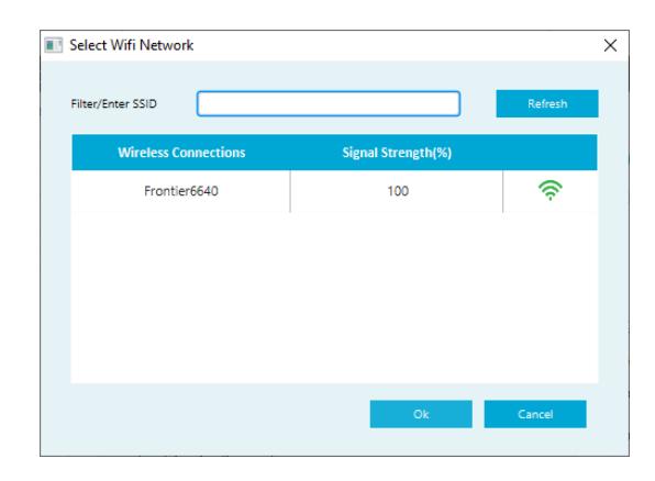
• Security Type:
Enter the security type for the SSID. Use the dropdown list, or manually enter the appropriate security type.
• Key (AES):
Enter the key value. Select the Hide Characters checkbox to hide the key value.
NOTE: Hidden SSIDs show up as Other Network . Select Other Network and enter the SSID manually.
NOTE: The network information needs to be obtained from the IT Department and/ or representative prior to configuration.
Lock Protocol Encryption
These settings are only used for sites using individual lock AES keys and require the key to also be applied to the DSR/access control system side. Click the Generate button to generate the required key to be entered in the Key text box. Then select the Enable or Require option.
Custom Network Settings
The LenelS2 Netbox Mode check box must be selected for PoE locks that will be communicating with a LenelS2 Netbox. DO NOT select this mode if using DSR or any other EAC system/panel other than Netbox.

4.1.3 Reader Tab
In the Reader tab, enter the following information:
Select the desired credential technology types for the system. Choose the mostused type for slot 0, then choose the next used types for the other slots.
In the Card Data Type dropdown select either Application or CSN.
MIFARE Classic and DESFire types require entering several additional fields for proper configuration of the reader for that credential. The data will be specific to each credential type/ site.
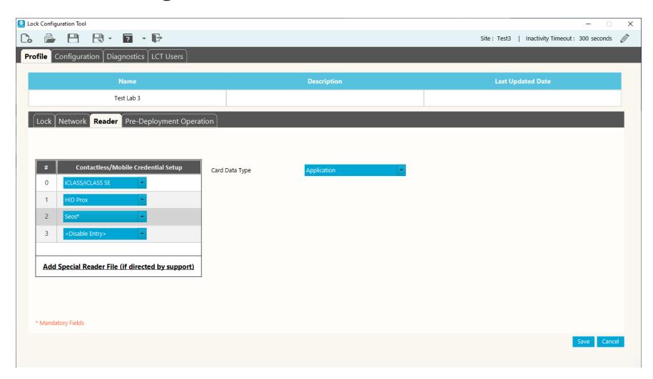
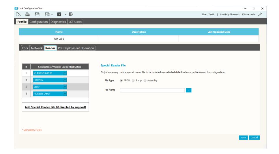
If directed by Support, click Add Special Reader File . Select the file type (APDU, Snmp, Assembly) and enter the file name in the File Name box. This feature allows for a special reader file to be added at the profile level and therefore more easily and seamlessly applied to all locks configured with this profile.
CAUTION: Only use a special reader file for very specific applications as directed by Support and always test for the desired results on one lock before applying to additional locks.
IMPORTANT: If PIV is being used, it must be selected for slot 0 and then any other card types can be selected for the other slots.

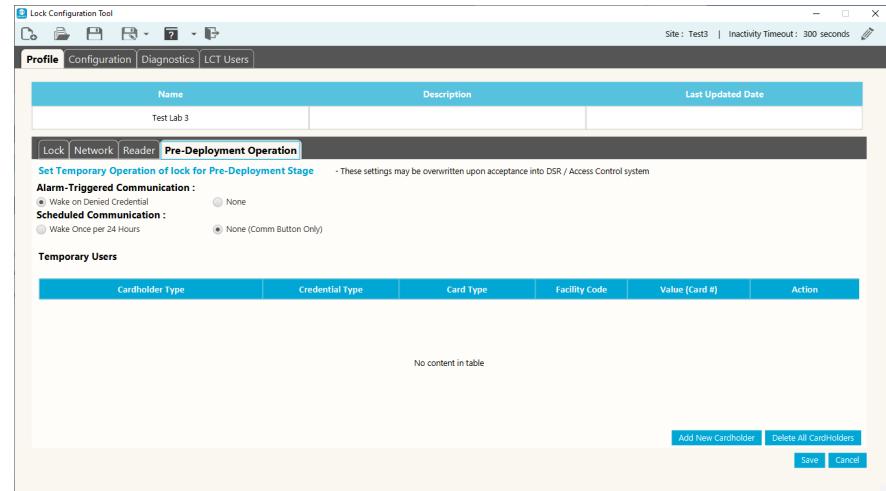
4.1.4 Pre-Deployment Operation Tab
In the Pre-Deployment Operation tab, set up temporary lock operation settings and add temporary users.
The settings may be overwritten after acceptance into the EAC system.
Choose the Alarm-Triggered Communication and the Scheduled Communication .
To add a Temporary User, do the following:
- 1. Click the Add New Cardholder button in the lower right of the screen. The Cardholder dialog box appears.
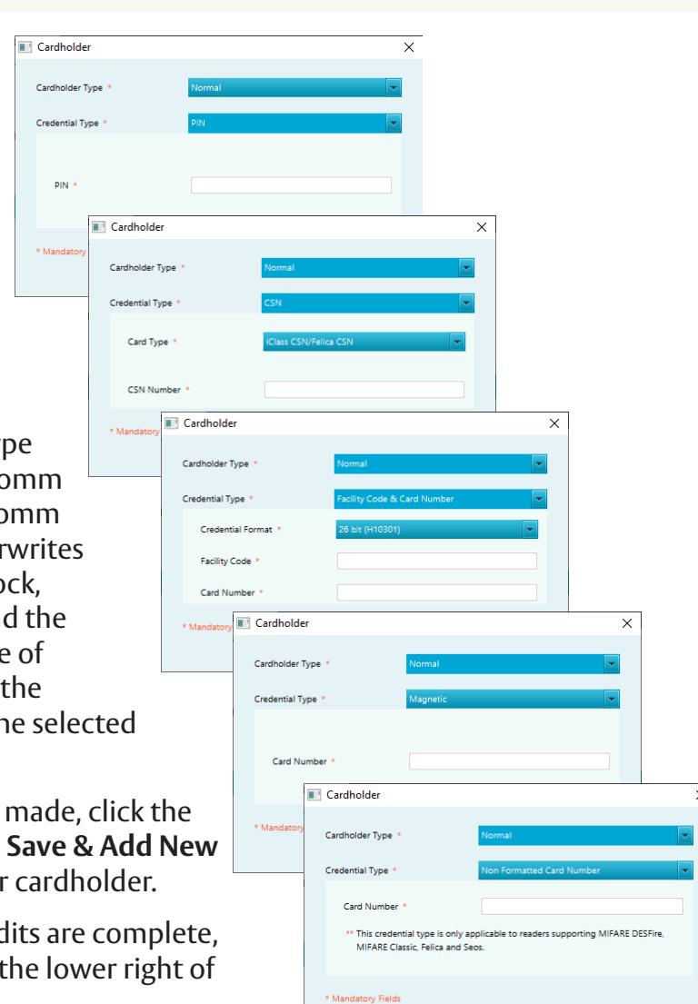
- 2. Select the Cardholder Type (Normal - typical user, Comm - functions as pressing comm button, Supervisor - overwrites any restrictions on the lock, i.e. deadbolt, privacy) and the Credential Type. The type of information entered for the credential depends on the selected Credential Type.
- 3. When the selections are made, click the Save button, or click the Save & Add New button to create another cardholder.
- 4. When all of the Profile edits are complete, click the Save button in the lower right of the screen.

4.2 Copy a Profile

To make a copy of a profile, from the main profile screen click the Copy button next to the name of the profile to copy.
LCT will copy the profile configuration parameters and automatically label the new profile as 'Copy'. If the Default profile is copied, the copy will become the new default. Uncheck the Default box if the new profile is not the new default.
4.3 Edit a Profile

To edit a profile, from the main profile screen click the Edit button next to the name of the profile to edit. The profile tabs appear. Make the desired changes to the profile on the various tabs, as described in Section "4.2 Copy a Profile" , and then click the Save button in the lower right of the screen.
4.4 View a Profile

To view a profile, from the main profile screen click the View button next to the name of the profile to view.
View Screen
Click the Edit button to Edit configuration parameters.
4.5 Delete a Profile

To delete a profile, from the main profile screen click the Delete button next to the name of the profile to delete. A delete confirmation dialog box appears. Click the OK button to confirm the profile delete.

5. Configuration
LCT maintains in the configuration file the list of locks configured. Once a lock is configured it will remain in the configuration file until manually removed. Refer to Section "5.2 Removing Lock from Previously Configured (History)" for instructions.
This Configuration screen supports configuring multiple locks consecutively without needing to leave the page or reselect configuration options that are desired to be maintained as different locks are configured. Once configuration is complete on one lock, the USB cable can be disconnected and then connected to the next lock needing configuration. LCT will continue to scan regularly until it detects the next lock. The same configuration can be applied by clicking the Go button, or selections can be customized as necessary.
5.1 Configuring a Lock
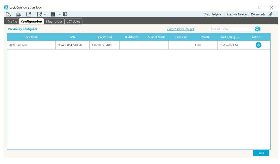
The Configuration tab regularly scans for a connected lock and displays detailed information about the connected device (where applicable). To view a detailed list of previously configured locks, click on View History in the lower right corner of the screen. This history page displays a searchable list of previously
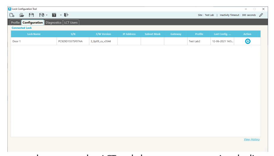
configured locks that are not currently connected to LCT and also supports exporting the list to a .CSV for a variety of potential/external uses.
Once at least one profile is created, locks can be configured. To access the configuration screen, click the Configuration tab and then click the Action button next to the lock name.


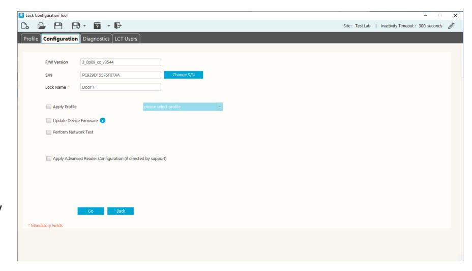
The following are provided in the Configuration screen:
- F/W version current firmware version
- S/N Lock Serial Number - click the Change S/N button to change the lock serial number (only necessary for a few scenarios, i.e. setting up a replacement controller
or moving a controller to a door with different lock hardware).
• Lock Name - name of lock (mandatory field)
NOTE: Changing the lock serial number must be done with care. Illegal configuration will result in unpredictable lock behavior. Contact Technical Support for assistance.
The checkboxes are used to select configuration activities. When the desired activities are selected, click the Go button at the bottom of the screen.
- Apply profile used to apply a profile to the lock. Select a profile using the dropdown list.
- Update Device Firmware used to download and install the most recent firmware for the lock.
- Perform Network Test used to test the connection to the network and to the DSR/EAC system the lock was configured to connect to.
- Apply Advanced Reader Configuration use this only if directed by Technical Support.

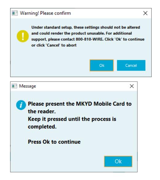
Apply Advanced Reader Configuration
These settings are used in certain circumstances. DO NOT change these settings unless directed to do so by Technical Support.
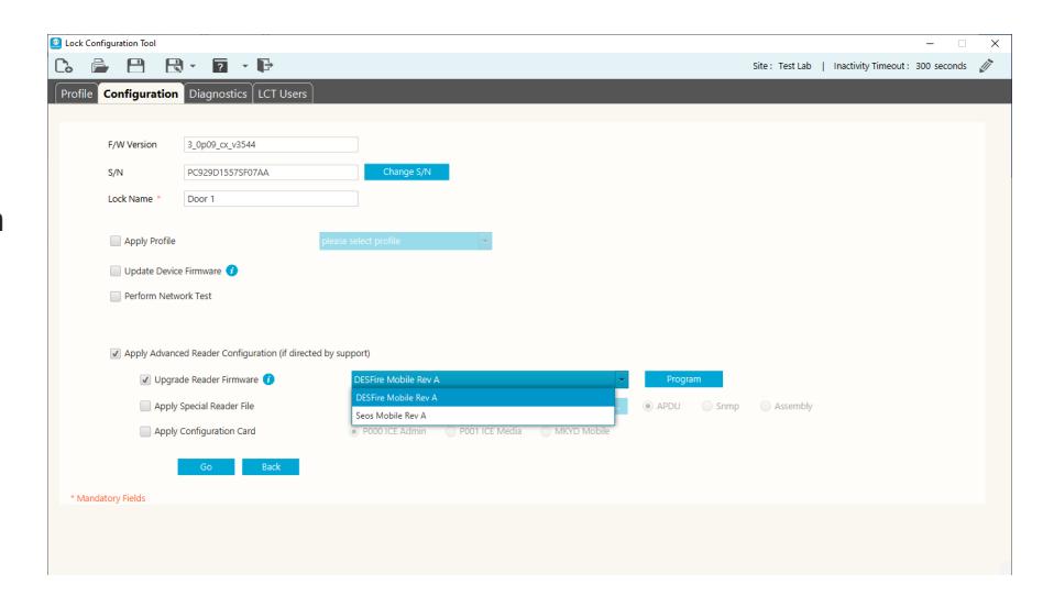
When the Apply Advanced Reader Configuration checkbox is selected, more options are displayed. These options include:
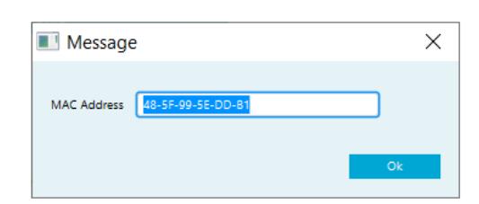
• Upgrade Reader Firmware - Request a token by clicking the Request Token button. After the Token is received, enter the token and click the Unlock button.
- Apply Special Reader file If a special reader file was added in the Reader tab of the profile, it will be applied to the reader when selecting that profile and configuring the lock. The option provided here is to allow a special reader file to be applied separately/individually to the connected lock. If needed, browse to select the file provided by Technical Support.
- Apply Configuration Card select the type of configuration card.
To request a Token, send the following information in an email to ProfessionalServices@assaabloy.com:
- Name of Site
- OTA version for non-DSR sites (Persona/Genetec/S2/ etc.)
- LCT version
- MAC Address this is displayed when the Request Token button is clicked
- Time Zone
- Specific Date or Date Range

Once the token is entered and the Unlock button clicked, select the appropriate firmware from the dropdown list and then click the Program button.
There are three different configuration cards used for different purposes. They are:

The Technical Support team at support.AEHG@assaabloy.com or 1.800.810.9473 can help determine which card or cards are needed for the operation desired.

5.2 Removing Lock from Previously Configured (History)
Once a lock is configured LCT stores the lock configuration information in the LCT file and the information is accessible in the Previously Configured (History) list until manually removed.
To view the Previously Configured list, click the View History link in the lower right corner
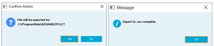
The Previously Configured (History) list can be exported to a .csv file by clicking Export list to .csv file at the top of the screen. A confirmation dialog box appears. Click Yes . The file is exported to the desktop and a completion message appears. Click OK in the message box.
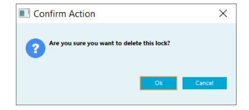
To remove a lock from the Previously Configured (History) list, search for the lock to be deleted and click the Delete (trash can) button next to that lock.
A Confirm Action dialog box appears. Click the OK button to confirm the delete action.


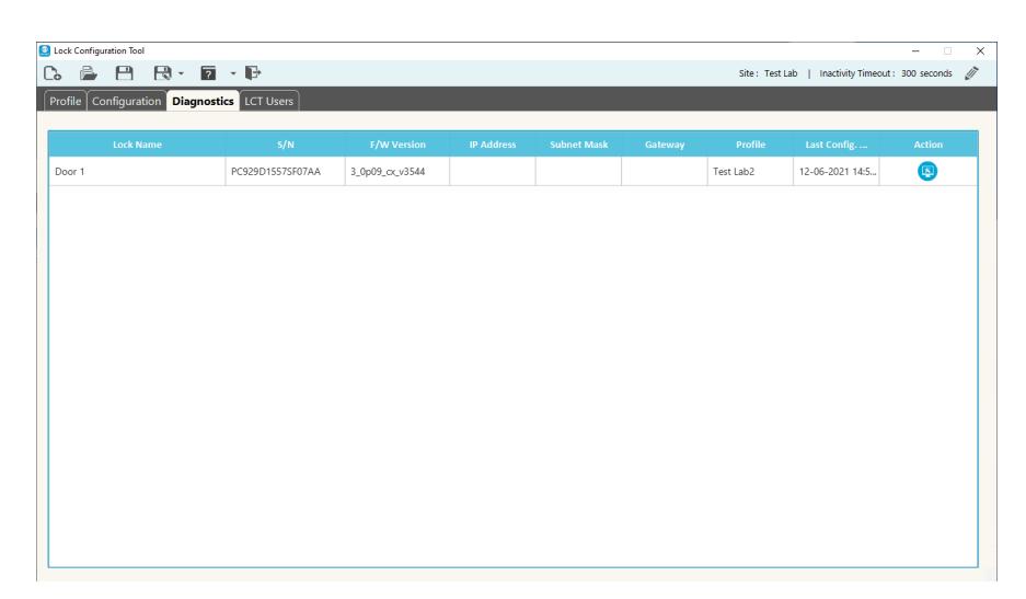
6. Diagnostics
To access the Diagnostic functions, click on the Diagnostics tab. To see the diagnostics options for a specific lock, click the Action button next to that lock.
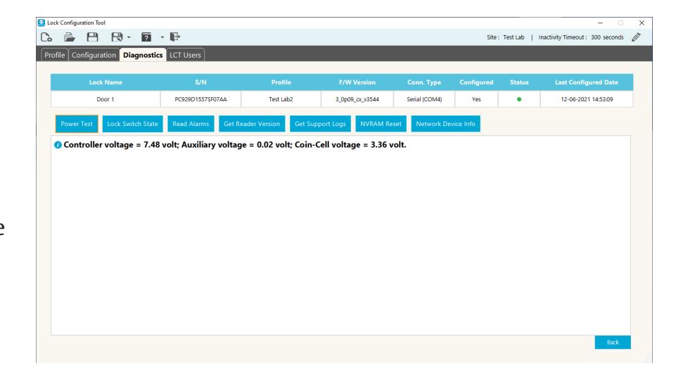
6.1 Power Test
Click the Power Test button to display the relevant voltages for the lock. This can be used to check the power source before performing a firmware upgrade. Voltage needs to be higher than 7.0 before performing a firmware upgrade.
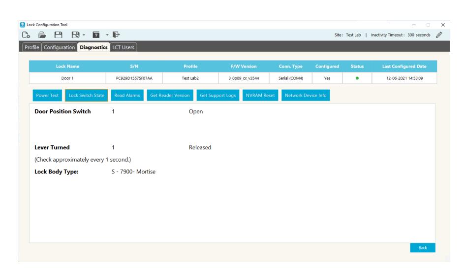
6.2 Lock Switch State
Click the Lock Switch State button to display the current Door Position Switch state and Lever Turned state. Switch states can be monitored while the applicable hardware is exercised (i.e. open/close the door, turn lever, throw/ retract the deadbolt) to check for expected state changes. LCT will continue to monitor the lock switch state every second.

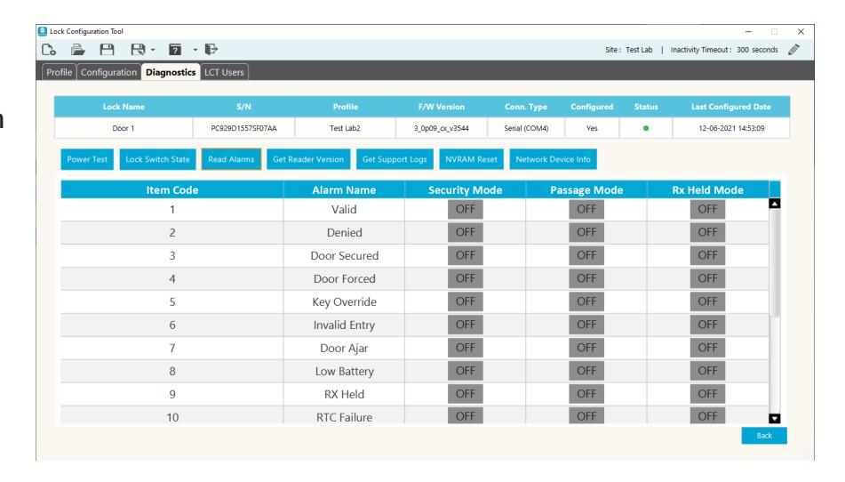
6.3 Read Alarms
Click the Read Alarms button to display the alarm settings for the lock.
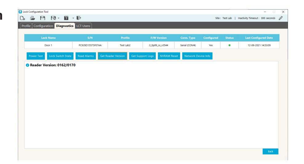
6.4 Get Reader Version
Click the Get Reader Version button to display the current reader firmware version for the lock.
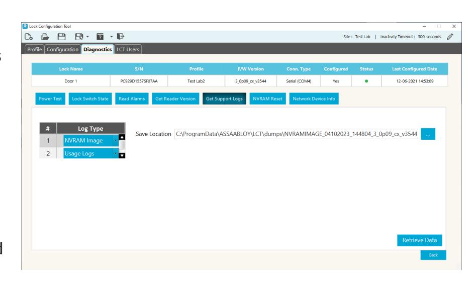
6.5 Get Support Logs
Click the Get Support Logs button to select the log type and specify a location to save the log files.
The log types are NVRAM Image and Usage Logs. The Save Location is displayed for the selected log type.
Click the Retrieve Data button to save the selected logs.

6.6 NVRAM Reset
NVRAM Reset can be used to clear a variety of configuration parameters that control the behavior of the lock. Use of this feature should not be required during normal operation of the lock but can be used during troubleshooting in an effort to clear an error state or if advised to by Technical Support. Depending upon the
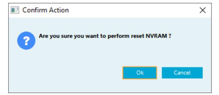
circumstances, it may also be advisable to reconfigure the lock after the NVRAM reset is performed.
NOTE: Specific logs are cleared as part of this reset process, including potentially relevant diagnostic information that could be useful during advanced troubleshooting. Therefore, the Get Support Logs option can be used to save this information prior to performing a NVRAM reset.
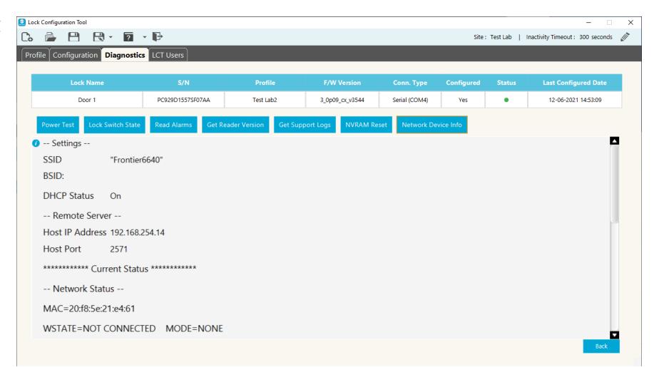
6.7 Network Device Info
This tab displays the current network information for the selected lock.
6.8 Exiting Diagnostics
Click the Back button in the lower right corner of the screen to return to the lock list.

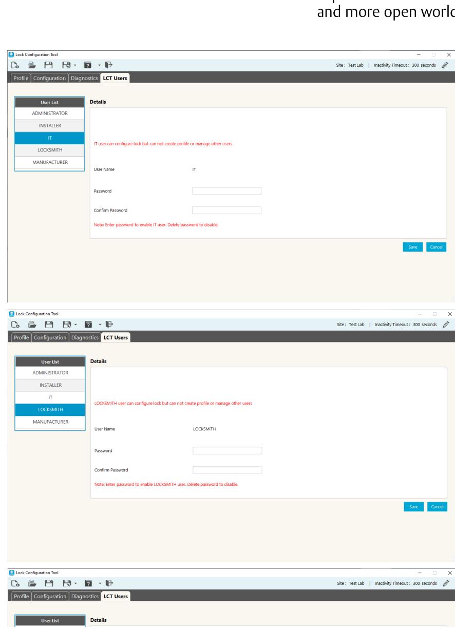
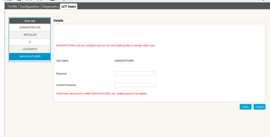
7. LCT Users
To access the LCT User information, click on the LCT User tab.
7.1 Roles and Responsibilities
There are five (5) system users available in LCT. All users have the ability to configure locks but not all can create or modify lock configuration parameters. Below is the list of system users along with a brief description of their roles and responsibilities:
Administrator Has access to all functionality. Responsible for creating the configuration file and profiles. Creates the initial passwords for each of the system users in order to grant access to the configuration file.
Installer - Lock Installer. Although the lock installer will have access to all functionality to ensure the proper lock installation, he/ she may require approval from the Administrator, i.e., card encryption keys, and/ or the IT user, i.e., network encryption key, to modify the network and/or reader configuration parameters as well as managing credentials.
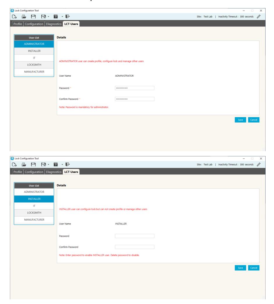

IT - Information Technology personnel. Mainly responsible for the network configuration and diagnostics. They can configure a lock but not create a profile.
Locksmith - Lock replacement and repairs. May be required to reconfigure the lock and perform diagnostics.
Manufacturer - Lock diagnostics. May be required to reconfigure the lock and perform diagnostics.

ASSA ABLOY Americas 110 Sargent Drive New Haven, CT 06511 USA www.assaabloy.com