ASSA ABLOY DSR Support Tool User Manual_SWMN21A
Open the original PDF document
View PDFDSR Support Tool
User Manual
Software Version 8

Experience a safer and more open world
Table of Contents
| 1. | Introduction1 | |
|---|---|---|
| 2. | Features and Functions1 | |
| Operating Environment 1 | ||
| Install/Upgrade1 | ||
| Login as Administrator 1 | ||
| Tool Bar | , | |
| Change Password2 | ||
| Help2 | ||
| Status Indicators3 | , | |
| DSR Status3 | ||
| EAC Callback Status | ||
| Viewing Lock Statuses4 | ||
| Lock Details6 | ||
| Radio Details6 | ||
| Reader Details7 | ||
| Status Details7 | ||
| Pending Commands7 | ||
| Events8 | ||
| Users In Lock8 | ||
| Timezones in Lock9 | ||
| Battery Graph10 | ||
| RSSI Graph10 | ||
| Viewing and Changing Lock Configuration11 | ||
| Controller Settings11 | ||
| AES Encryption | ||
| Device Specific Commands13 Configuring Wireless Lockset Contact Schedules in the DSR20 | ||
| System Configurations | ||
| Firmware Upload23 | , | |
| Network Settings25 | ||
| Radio Firmware Upload | ||
| Radio Certificate Update27 Network Configuration Update28 | ||
| Radio Configuration Creator29 | ||
| Upload Certificate Files to Server30 | ) |
DSR Support Tool User Manual

Experience a safer and more open world
| Reader Settings | 31 | |
|---|---|---|
| Reader Configuration | 31 | |
| Reader Files Update | 32 | |
| Upload Reader Files (apdu) to Server | 33 | |
| Server Settings | 34 | |
| WS Encryption and Port Configuration | ||
| Reports | ||
| Email & Battery Report Configuration | 37 | |
| Advanced Troubleshooting Tools | ||
| Decryption Utility | 38 | |
| Logging Utility | 39 | |
| Download Lock Image | 40 | |
| Utility | 41 | |
DSR Support Tool User Manual


1. Introduction
The DSR Support Tool is installed with the main DSR installer. This graphical user interface is used to look at what is running inside the DSR, i.e. objects such as locks, pending commands, events generated, time zones, and users. The DSR Support Tool also exposes information regarding general connectivity and database health. In addition, the DSR Support Tool allows the end user to configure some items that might not be available in the access control software platform. Access to the DSR Support Tool is secured by a password, set at install time.
Operating Environment
Browser Compatibility: IE 9.0 and above, Mozilla Firefox
The DSR Support Tool runs with the same overall server requirements as the DSR.
NOTE: See the DSR Installation Guide for more information about the DSR server requirements.
2. Features and Functions
This section details the main features and functions of the DSR Support Tool.
Install/Upgrade
The Support Tool is installed and upgraded as part of the DSR installation process.
The DSR installer creates a desktop icon to launch the DSR Support Tool.
The DSR uninstall process also uninstalls the DSR Support Tool.
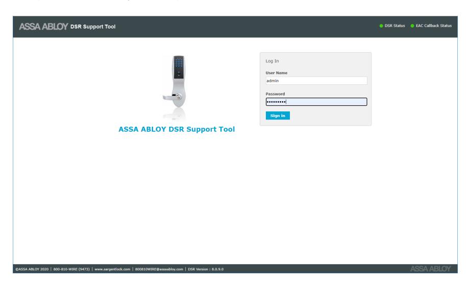
Login as Administrator
By default, the Support Tool is accessible only at the local host by accessing one of the following:
- http://127.0.0.1:8080/dsrsupport/ (if SSL security is OFF)
- https://127.0.0.1:8443/dsrsupport/ (if SSL security is ON)
Please make sure the DSR service ASSA ABLOY Door Service Router is up and running.
Users can access the DSR Support Tool by entering valid credentials into the Sign In window. These credentials were created during the installation of the DSR.

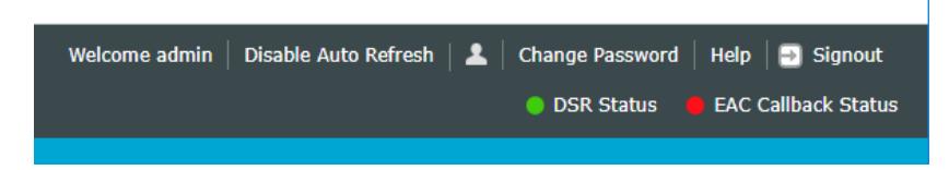
Tool Bar
The Tool Bar is located at the top of the screens. It includes functions such as Change Password, Help, and Signout. It also includes status indicators.

Change Password
This feature allows the end user to change the Support Tool password.

Help
This feature opens a help file where users can find assistance and information about how to perform functions in the software.

Status Indicators
There are two status indicators present on the top right corner of the screen. These indicators are:
- DSR Status
- EAC Callback Status
By default, DSR Status and EAC Callback Status are refreshed automatically every minute.
If the status indicator is Red, a message is displayed.
DSR Status
This feature indicates DSR health. It checks the DSR service is up and running.
- Red indicates DSR and postgres service is not working properly
- Green indicates DSR and postgres service is working properly
EAC Callback Status
This feature checks if the DSR can make a connection with the EAC system.
- Red indicates DSR is not able to connect to the EAC system. An error message may appear. Follow the instructions in the error message.
- Green indicates DSR is able to connect to the EAC system

Viewing Lock Statuses
To view lock statuses, click on the Facility View tab at the top of the page. The Facility View gives a detailed view of the current status of all access points in a sortable list. There is one panel on Facility View page, Lock List.
The Lock List page displays details pertaining to access points configured in the DSR. Details include:
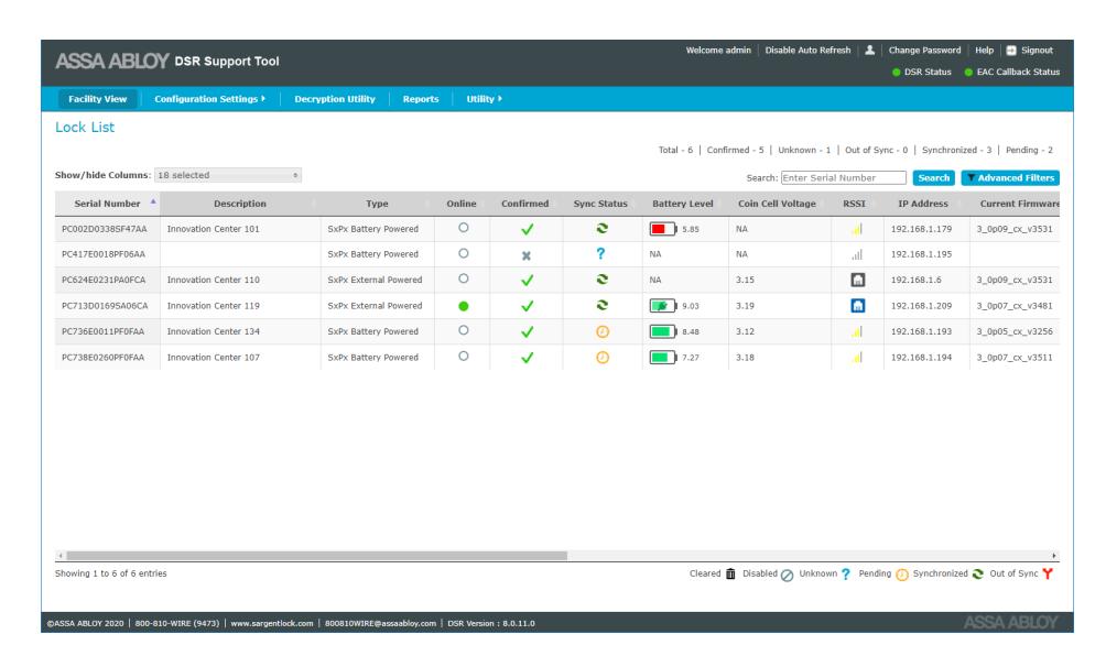
- Serial no: By default the lock list table is sorted by serial number. The lock serial number is printed on the lock controller.
- Description: This column displays the description of the lock, if set. This field is typically the door name. This might be set by LCT or by the host access control software.
- Type: Identifies the type of lock as battery powered or external powered. External powered includes both Power over Ethernet (PoE) and hard-powered WiFi.
- Online: This column shows if the lock is online or not. Please note that battery powered locks will be listed as offline unless they are in the middle of a session.
- Confirmed: This shows if the access control software has accepted the lock into the system. A solid green circle indicates online and connected. A white circle indicates offline.
- Sync Status: Symbolic notation of the different synchronization status of the lock. The descriptions are:

- Cleared: This indicates that access point data (users, schedule, etc.) will get cleared.
- Disabled: This indicates that DSR will ignore all communication from the access point.
- Unknown: This indicates that the access point is not confirmed.
- Pending: This indicates that there are some pending commands in the queue.
- Sychronized: This indicates that no pending changes exist in DSR and the access point is sychronized.
- Out of Sync: This indicates that this access point is not synchronized with DSR. When out of sync it shows the error and reason for this state.

-
Battery Level: This shows the charge status of the battery used in the locks.
- Green: if battery voltage is greater than or equal to 7.0 volts.
- Yellow: if battery voltage is between 5.9 volts and 7.0 volts.
- Red: if battery voltage is less than 5.9 volts.
- Coin Cell Voltage: Last reported coin cell battery voltage. Not all locks report coin cell voltage.
- IP Address: This shows the last reported IP address of the lock.
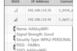
- RSSI: For WiFi locks, this displays the last reported signal strength on hover. PoE locks do not have a signal level to report.
- Current Firmware: This shows the current firmware version of the lock.

- Last time lock online: This shows the last time (Start time) when the lock came online.
- Estimated Battery Replacement Date: This is the estimated date when the battery may need replacement for battery powered locks. This estimate is based on historical data for this given lock. Locks recently added may not have enough data to display an estimate.
- Radio Firmware Version: This shows the current radio firmware version.
- Radio Type: This shows the current radio type of lock.
- Radio Upgrade Status: This shows the radio upgrade status.
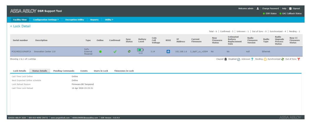
Once a lock is selected from the Lock List, the bottom panel expands and the default tab Lock Details is opened.
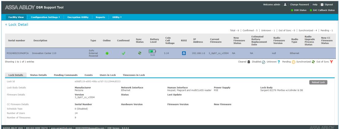
The tabs are: Lock Details, Radio Details, Reader Details, Status Details, Pending Commands, Events, Users In Lock, Timezones in Lock, Battery Graph, RSSI Graph.
Note that some tabs are not displayed, depending on the lock hardware/configuration.

Lock Details
This tab shows the details of the selected lock, including:
- Lock ID
- Lock Body Details, Enhanced Mode
- Firmware Details
- Schedule Type
- Number of Users
- Number of timezones in the lock
- Estimated Battery Replacement Date
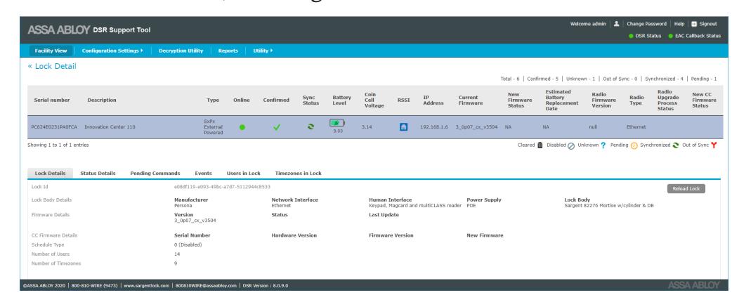
The Reload Lock button is disabled (grey) unless the selected lock is out of sync (in an error state). The button is used to clear all the access rights and configuration settings and then send them again to clear the out of sync issue.
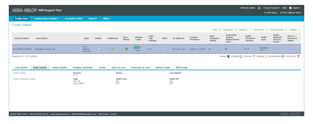
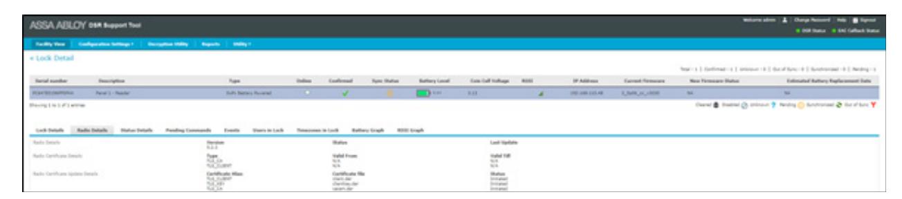
Radio Details
This tab shows the radio firmware and radio certificate details of the selected lock.

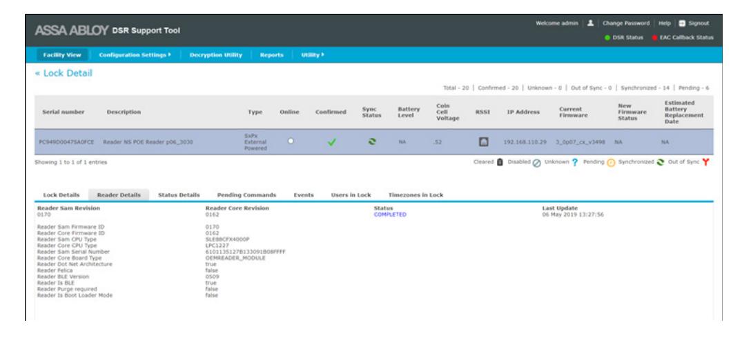
Reader Details
This tab shows the reader details of the selected lock.
Status Details
This tab shows the Last Time Lock Online, Next Expected Online schedule, Lock Reload Reason, Last Time Lock Reload of the lock.
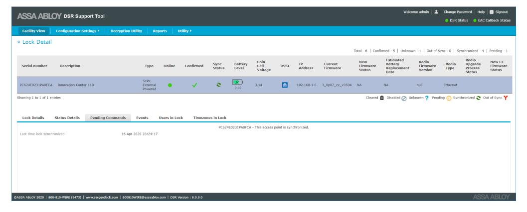
Pending Commands
This tab shows the list of pending commands on the selected lock.

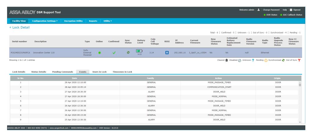
Events
This tab shows the list of the last 200 events sent to the DSR. Certain events create multiple entries in this even log.
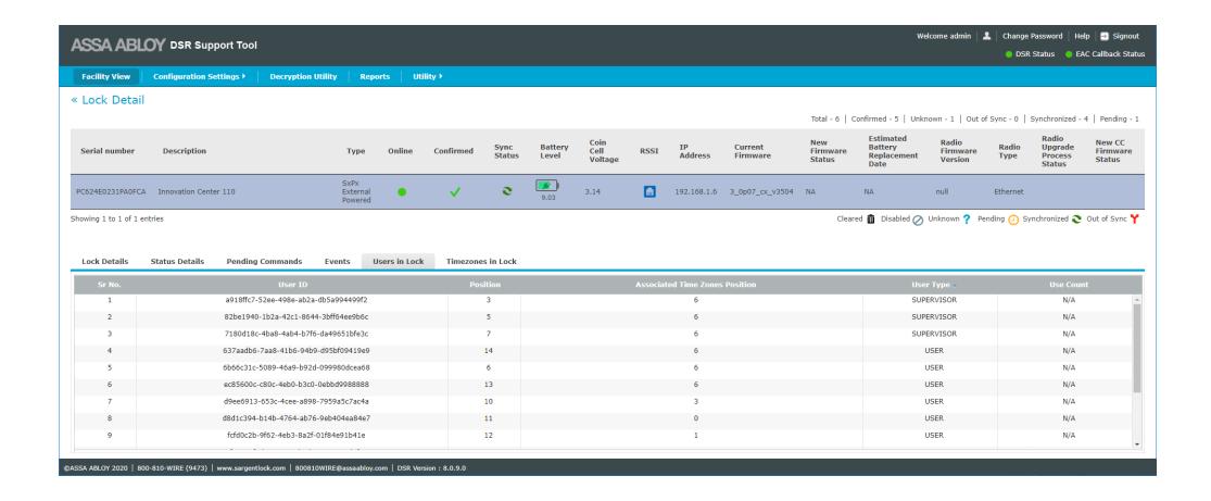
Users In Lock
This tab shows the user details that exist in the lock. The user's ID, user position in the lock, associated tome zone position, and user type is shown in tabular format. All columns are sortable.
NOTE: For one time users, the remaining/available use count is displayed in the User Count column. For users other than "one time", this column shows N/A (Not Applicable).

Timezones in Lock
This tab shows time zone positions occupied in the lock. Associated schedule ID, schedule start time, end time, time zone position, time zone mode and schedule days are displayed in tabular format.
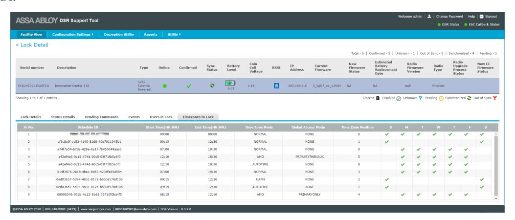
Time zone definitions:
- Normal users assigned to this timezone have access during it.
- UAPM User Activated Passage Mode, users assigned to this timezone can double swipe to leave the door unlocked for the duration of the timezone. They can double swipe to relock it.
- AutoFPT First Person Through the door with valid access during the timezone causes the door to unlock for the duration of the timezone.
- AutoTime the door automatically unlocks for the duration of the schedule.
- AMO used for changing credential requirements, e.g. card only versus card and pin, on schedule.

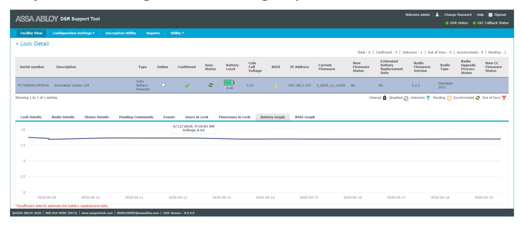
Battery Graph
This tab shows the current status of the battery and estimated battery replacement date of the selected lock. This tab is not visible for PoE and hard powered locks. Estimated battery replacement date is calculated based on historical data for each lock. Recently added locks to the system may not have enough data to estimage replacement date.
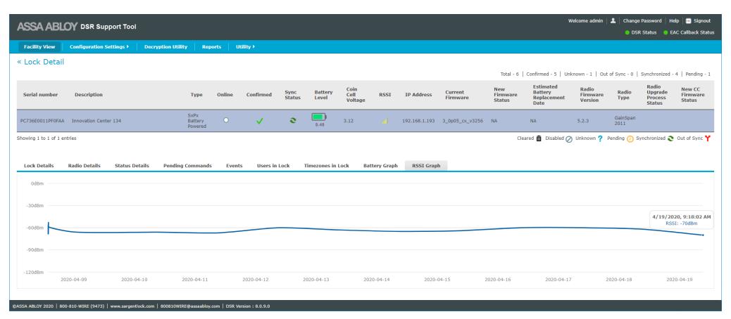
RSSI Graph
This tab shows the previously reported signal strength of the network signal in a graphical format. This tab is not visible for PoE and legacy locks.

Viewing and Changing Lock Configuration
The Configuration Settings tab allows the user to make changes to the DSR and lock configuration with functions such as Controller Settings, Network Settings, Reader Settings, and Server Settings. Each of these options can have multiple selections.
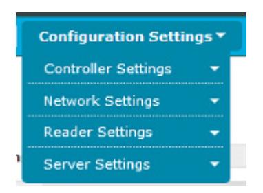
Controller Settings
The Controller Setting menu allows the user to select controller options such as AES Encryption, Device Specific Commands, System Configurations, and Firmware Upload.
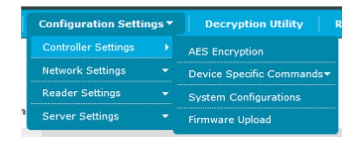

AES Encryption
This screen allows the user to set the AES encryption key. This key is used to encrypt the messages between the lock and the DSR. The AES Encryption Key Configuration screen is accessed from Configuration Settings>Controller Settings>AES Encryption .
WARNING: Many DSR integrations support the configuration of AES key settings through the access control system application. If the host software supports a feature exposed here, DO NOT configure it in the DSR. Otherwise the host application may occasionally overwrite these settings and cause confusion at the system operator and cardholder level. Please contact technical support if you are unsure about whether to configure an option in the DSR or in the host application.
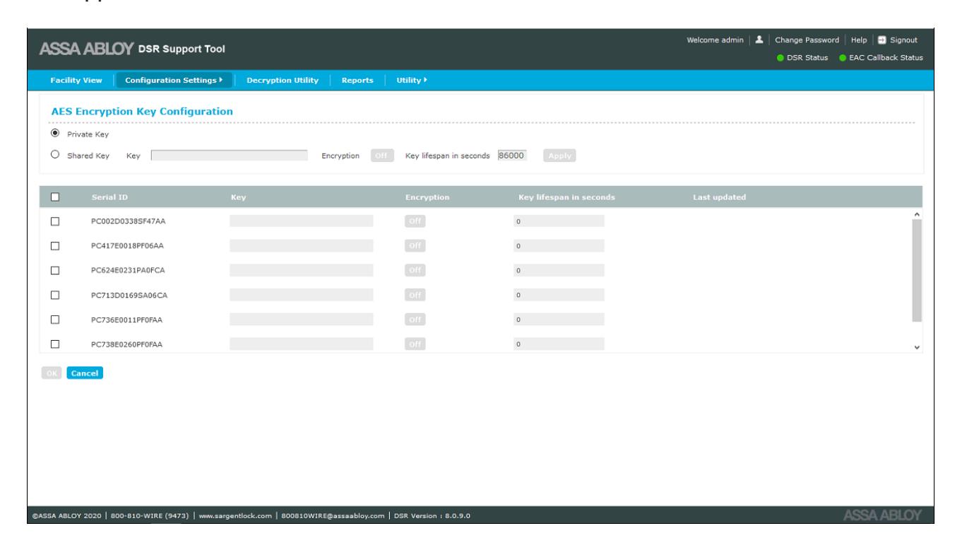
The top part of the screen allows the user to select the Key Type, either Private Key (default)or Shared Key. Shared Key uses one (starting) AES key for all locks in the system for easier setup. If the key lifespan is set to anything other than 0, the key for each lock will roll to a unique value. Private Key sets a unique starting key for each lock from the very beginning.
If Shared Key is selected, the following settings have to be made:
- Key this is the key identification number (32 character hexadecimal string)
- Encryption select On or Off (default)
- Key lifespan in seconds default value is 86000 seconds. The allowed range is 60-86000. The key will not roll over if the value is set to 0.
DSR Support Tool User Manual

NOTE: If using this feature, the initial key loaded in the DSR Support Tool MUST match the initial key loaded into the lock with the Lock Configuration Tool (LCT). To manually change or reset the key on the lock, an initial key will need to be loaded into the lock with LCT.
The bottom part of the screen contains a lock list. Only confirmed locks are displayed. Each lock is displayed with the lock Serial Number, Encryption Key, Encryption status (on/off), Key Lifespan value, and when the key was last updated.
To edit lock information when Private Key is selected, click on the checkbox next to the desired lock Serial Number. This allows the Encryption Key, Encryption Status, and Key Lifespan fields to be edited. If the Encryption Status is set to ON, values must be entered in the Encryption Key and Lifespan fields. If Encryption Status is set to OFF, the Encryption Key and Lifespan fields must be blank. Save the changes by clicking the OK button.
To edit lock information when Shared Key is selected, select multiple locks from the list by clicking on multiple checkboxes. Enter the shared encryption key in the Encryption Key field in the top part of the screen. Set the Encryption Status to ON and set the Lifespan value. Click the Apply button to apply the shared key to the selected locks. Once the key is applied, click the OK button to save the changes.
To turn off the Encryption Key, select multiple locks from the list by clicking on multiple checkboxes. Change the Encryption Status to OFF. Click the Apply button. Click the OK button to save the changes.
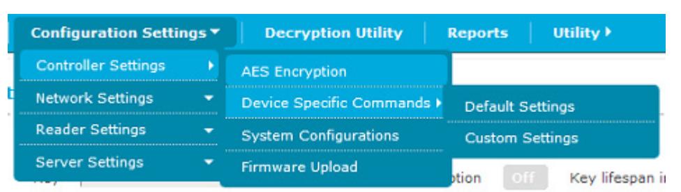
Device Specific Commands
This menu has two selections, Default Settings and Custom Settings, that allow the user to set the system defaults and custom settings for locks.
WARNING: Most DSR integrations support the configuration of many Device Specific Commands through the access control system application. If the host software supports a feature exposed here, DO NOT configure it in the DSR. Otherwise the host application may occasionally overwrite these settings and cause confusion at the system operator and cardholder level. Please contact technical support if you are unsure about whether to configure an option in the DSR or in the host application.

Default Settings
Default Settings allow the user to add or update the default configuration items, filters, alarms, or lock limits. The default parameters are saved in the DSR database and will be sent to each lock once the lock is confirmed. For existing locks, if default configuration settings are added to each lock once or updated, the latest settings are applied only if custom settings are not set for the lock. Custom settings always supercede the default settings.
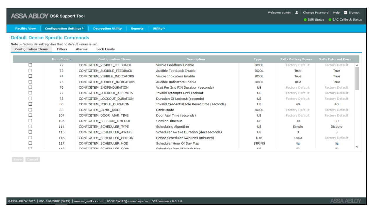
There are four tabs on this page:
- Configuration Items (default selection)
- Filters
- Alarms
- Lock Limits
DSR Support Tool User Manual

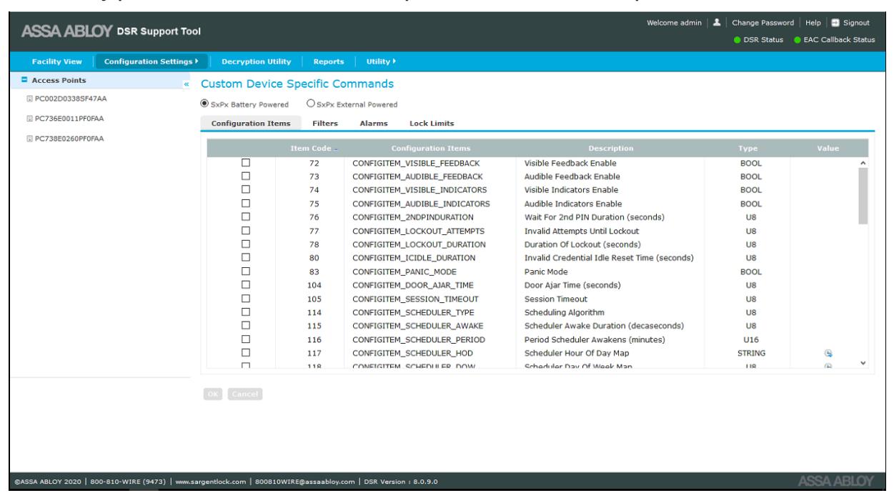
Configuration Items
This table shows a list of configuration parameters that can be set as default. The following fields are displayed:
- Check box for configuration item selection
- Item Code (default sorted)
- Configuration Item
- Description
- Item
- SX PX Battery Powered (editable field)
- SX PX External Powered (editable field)
Parameters can be edited after selecting the checkbox. Parameters which are not set as default in DSR are shown as 'factory default', which means that no default values are set. A few of the parameters have predefined values set in DSR that are displayed in the list. These values can be updated but they cannot be set to be blank.
Once the defaults are defined, only those settings may be updated. Settings cannot be set back to a 'factory default'.
To set default configuration items, do the following:
- 1. Select the checkbox for the configuration items to be set as default, multiple selection is possible.
- 2. Select or set the value in the SX PX battery powered column or the SX PX external powered column, or both. The values in the SX PX battery powered column define the default values to be set on Wi-Fi battery powered locks. The values in the SX PX external powered column define the default values to be set on external powered locks.
- 3. Once all values are selected, click the SAVE button. A success message is displayed.
Some of the Configuration Items have Tool Tips that provide guidance on setting values, such as setting ranges, setting increments, etc. To see the Tool Tip, mouse over the Configuration Item.

Filters
NOTE: Many EAC systems have built-in event filtering. It may be preferable to filter the events at the EAC level instead of lock or DSR. Please contact your EAC's technical support before filtering out any events in the DSR Support Tool.
This tab has two radio buttons, SX PX Battery Powered (default selected) and SX PX External Powered. The table shows a list of locks based on the radio button selection. The following fields are displayed:
- Check box for event filter selection
- Item Code (default sorted)
- Event filters
- Reporting toggle button (ON/OFF) controls whether an event is reported to the access control software
- Recording toggle button (ON/OFF) controls whether an event is recorded locally at the lock controller
NOTE: If the reporting and/or recording toggle switches are set to ON for any event filter, that event will NOT be recorded and/or reported. An ON setting means the event is being filtered out. An OFF setting means the event is being recorded/reported.
For an event to be reported, recording must also be allowed. If an event is not recorded, it cannot be reported.
By default there are ten (10) event filters that have reporting and recording set to ON. These events are filtered out by default.
INVALIDPIN USERADDED USERDELETEDCOMENDED
COMUSER NVRAMOK USERREPLACED USERUPDATED
CHECKSUMCONFIG CHECKSUMTZ
To set default filters, do the following:
- 1. Select the checkbox for the filters to set as default, multiple selection is allowed. Edit mode is enabled for the selected filters.
- 2. Set the toggle button in the Reporting column to ON to filter out reporting.
- 3. Set the toggle button in the Recording column to ON to filter out recording.
- 4. Click the SAVE button. A pop-up success message appears.
- 5. Click the OK button.
If custom filters ARE NOT present for the locks (selected based on door type), then the updated default values are pushed to all the locks specific to the selected door type.
DSR Support Tool User Manual

If custom filters ARE present for the locks (selected based on door type), then a pop-up message appears asking the user if they want to overwrite the custom settings. Clicking the OK button in the pop-up updates the locks and overwrites the custom settings. Clicking the CANCEL button in the pop-up updates only the locks that do not have custom filter values.
Alarms
This tab has two radio buttons, SX PX Battery Powered (default selected) and SX PX External Powered. The table shows a list of locks based on the radio button selection. The following fields are displayed:
- Check box for alarm selection
- Item Code (default sorted)
- Alarm Name
- Security Mode (ON/OFF)
- Passage Mode (ON/OFF)
- Rx Held Mode (ON/OFF)
- Log When Secure (ON/OFF)
- Log In Passage (ON/OFF)
- Log When Rx Held (ON/OFF)
To set default alarms, do the following:
- 1. Select the checkbox for the alarms to set as default, multiple selection is allowed. Edit mode is enabled for the selected alarms.
- 2. Set the toggle button in any or all of the columns to set the desired alarm configuration.
- 3. Click the SAVE button. A pop-up success message appears.
- 4. Click the OK button.
If custom alarms ARE NOT present for the locks (selected based on door type), then the updated default values are pushed to all the locks specific to the selected door type.
If custom alarms ARE present for the locks (selected based on door type), then a pop-up message appears asking the user if they want to overwrite the custom settings. Clicking the OK button in the pop-up updates the locks and overwrites the custom settings. Clicking the CANCEL button in the pop-up updates only the locks that do not have custom alarm values.
DSR Support Tool User Manual

Lock Limit
This tab displays a list of lock limits that can be set as defaults. The following fields are displayed:
- Check box for limit selection
- User Limit (10000 default)
- Time Zone Limit (256 default)
- Exception Limit (256 default)
- Exception Group Limit (256 default)
- Event Log Entries Limit (30000 default)
- Declined Log Entries Limit (30000 default)
- Alarm Log Entries Limit (30000 default)
- Network Log Entries Limit (512 default)
- Command Log Entries Limit (2048 default)
NOTE: These settings should only be adjusted if directed to do so by technical support.
To set a lock limit, do the following:
- 1. Select the checkbox for the lock limits to set as default, multiple selection is allowed. Edit mode is enabled for the selected lock limits.
- 2. Change the values for the selected lock limits.
- 3. Click the SAVE button. A pop-up success message appears.
- 4. Click the OK button.

Custom Settings
Custom Settings allow the user to set the customized configuration items, filters, and alarms to all battery powered locks or all external powered locks, or to a specific lock.
Custom Settings to All Locks:
The Custom Device Specific Commands page displays custom commands. The left panel displays a list of locks. The locks displayed can be Battery Powered or External Powered locks, depending on the radio button selection. By default Battery Powered locks is selected. The four tabs, Configuration Items, Filters, Alarms, and Lock Limits are the same as they are for the Default Settings. Please refer to the sections above for details in setting each of these items.
Custom Settings to a Specific Lock:
To set custom settings to a specific lock, select the lock from the list in the left panel on the screen. Any settings made to items in the Configuration Items, Filters, Alarms, and Lock Limits tabs will apply only to the selected lock. The four tabs, Configuration Items, Filters, Alarms, and Lock Limits are the same as they are for the Default Settings. Please refer to the sections above for details in setting each of these items.

Configuring Wireless Lockset Contact Schedules in the DSR
The following configuration parameters determine the exact contact time for a battery powered WiFi lock. The default contact schedule for a battery powered Wi-Fi lock is once every 24 hours. When defining your own wakeup schedule, it is recommended to not schedule more than 50 locks to connect at the same time.
- CONFIGITEM_SCHEDULER_TYPE-114
- CONFIGITEM SCHEDULER PERIOD-116
- CONFIGITEM SCHEDULER HOD-117 [Hour of day scheduling]
- CONFIGITEM SCHEDULER DOW-118 [Day of week scheduling]
- CONFIGITEM SCHEDULER DOM-119 [Day of month scheduling]
- CONFIGITEM SCHEDULER HM1-120 [On at hour:minute #1]
- CONFIGITEM SCHEDULER HM2-121 [On at hour:minute #2]
- CONFIGITEM SCHEDULER HM3-122 [On at hour:minute #3]
- CONFIGITEM SCHEDULER HM4-123 [On at hour:minute #4]
CONFIGITEM_SCHEDULER_TYPE-114
This parameter determine which scheduling algorithm is used:
- SCHEDULERTYPE_SIMPLE [1] connect every X minutes
- SCHEDULERTYPE_DOM [2] connect at specific times on certain calendar days of the month
- SCHEDULERTYPE_DOW [3] connect at specific times on certain, or all, days of the week. Supports up to four (4) wake ups per day.
- SCHEDULERTYPE_COMMUSER [4] lock does not wake up on any schedule. Will wake up only when a special credential is presented or a real-time alarm occurs.
- SCHEDULERTYPE_HOD [5] connect at specific times on certain, or all, days of the week. Support more than four (4) wake ups per day.
- SCHEDULERTYPE_OFF [6] not recommended
- SCHEDULERTYPE_HARDON [0] radio is always on (battery powered locks should not be set to this)
For the SCHEDULERTYPE_SIMPLE, SCHEDULERTYPE_DOM, SCHEDULERTYPE_DOW, and SCHEDULERTYPE_COMMUSER modes, the radio is normally off and only powered up when either a scheduling condition is met, as in the case of SIMPLE, DOM, and DOW, or a Comm User credential is presented.

How to Enable Scheduling of Different Modes
- To have the lock always online: Set CONFIGITEM_SCHEDULER_TYPE 114 to 0 (always connected). This should NOT be used for battery powered locks as it will rapidly exhaust the battery.
- To have the lock wake up every x minutes: Set CONFIGITEM_SCHEDULER_TYPE 114 to 1. Set x is with CONFIG #116 - Period Scheduler Awakens. Value may be from 1 to 65535 minutes.
-
To have the lock wake up certain times of day on certain days of the calendar month: Set CONFIGITEM_SCHEDULER_TYPE 114 to 2. Set CONFIG #119 - Scheduler Day of Month Map to choose the days of the month. Set up to four (4) exact times of day using Configuration Parameters (set a time to 00:00 to disable it):
- 120 Scheduler on at Hours:Minutes #1
- 121 Scheduler on at Hours:Minutes #2
- 122 Scheduler on at Hours:Minutes #3
- 123 Scheduler on at Hours:minutes #4
-
To have the lock wake up at certain times of day on certain days of the week: For four (4) or fewer wakeups per day, set CONFIGITEM_SCHEDULER_TYPE 114 to 3. Choose days of the week with CONFIG #118 - Scheduler Day of Week Map. Set up to four (4) exact times of day using Configuration Parameters (set a time to 00:00 to disable it):
- 120 Scheduler on at Hours:Minutes #1
- 121 Scheduler on at Hours:Minutes #2
- 122 Scheduler on at Hours:Minutes #3
- 123 Scheduler on at Hours:minutes #4
For more than four (4) wakeups per day, set CONFIGITEM_SCHEDULER_TYPE 114 to 5. Select CONFIGITEM SCHEDULER HOD 117 and select the desired wake up times. Select CONFIGITEM)SCHEDULER_DOW 118 and select the desired days of the week.
• To disable scheduled wakeup: Set CONFIGITEM)SCHEDULER_TYPE 114 to 4 (not recommended to disable scheduled wakeup).

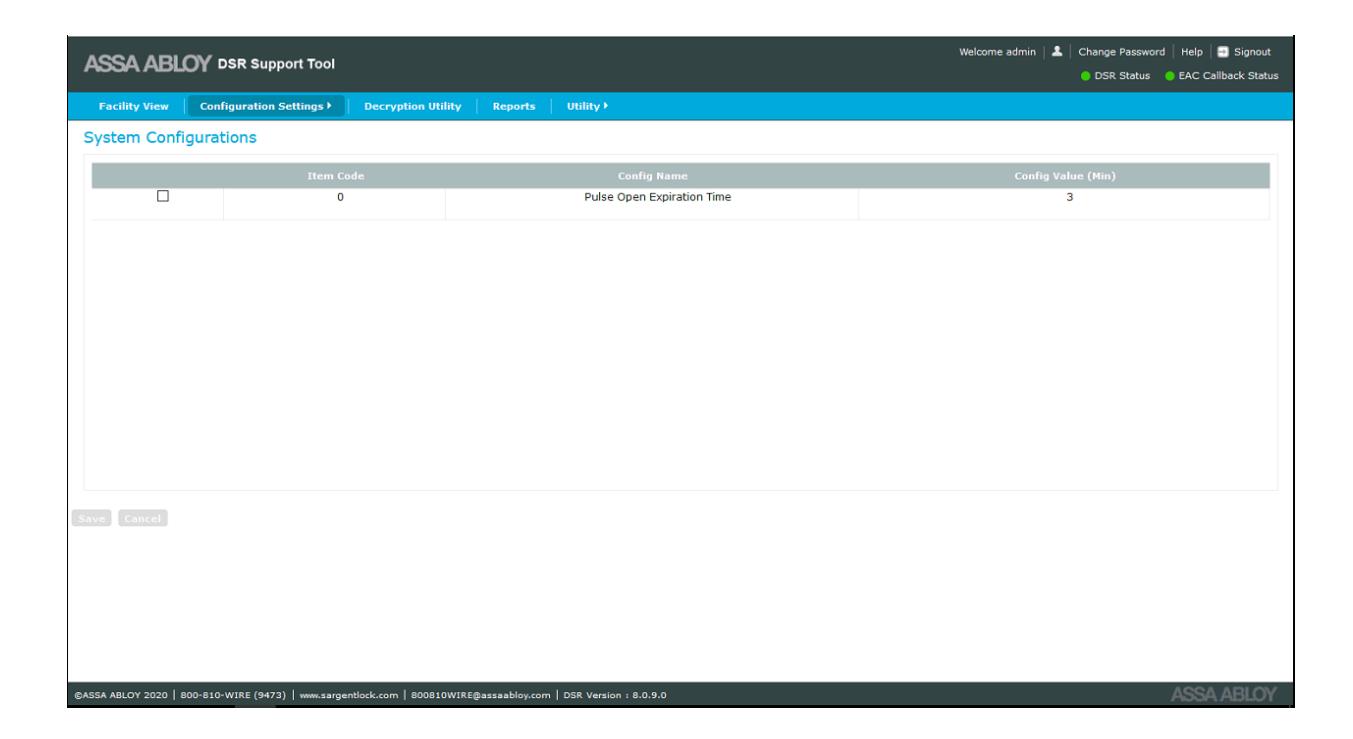
System Configurations
This screen allows the user to set Pulse Open expiration time in milliseconds. This time determines the maximum time an unlock command from the EAC will be held for a battery powered Wi-Fi lock.
The System Configurations screen is accessed from Configuration Settings>Controller Settings>System Configurations .

Firmware Upload
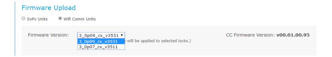
This screen allows the user to upload controller firmware to a batch of locksets. The firmware upload screen is accessed from Configuration Settings>Controller Settings>Firmware Upload .
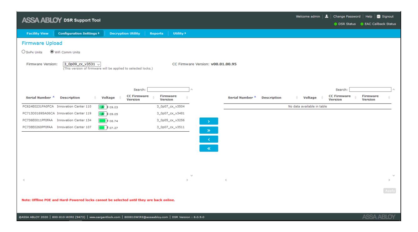
By default, the latest firmware version is selected in the Firmware Version dropdown list. The latest version or any other available firmware version can be selected from the list.

There are two panels on the Firmware Upload screen:
- Left panel shows a list of all confirmed Sx/PX battery or external powered locks for which DSR knows the existing firmware versions. Details of the locks (lock type and firmware version) are displayed along with the serial number in the left panel.
- Right panel shows the list of locks selected for firmware upload.
To select a lock for firmware upload, select the desired lock in the left panel and click the > button. To select all of the locks, click the >> button.
To remove a lock from the firmware upload list on the right panel, select the desired lock and click the < button. To remove all of the locks from the upload list, click the << button.
When all of the desired locks are in the right panel, click the Apply button. If there are no locks listed in the right panel, the Apply button is disabled.
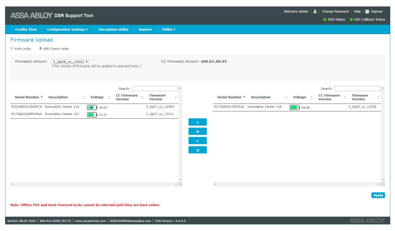
A message prompt appears on the screen with a notification of the firmware upgrade. Each lock selected will be upgraded on its next session. Once a lock begins its download, the process will take several minutes, during which time the lock will be unresponsive.
NOTE: Hard powered (always connected) locksets will begin updating immediately. Wireless locks that are disconnected are queued for an upgrade upon their next connection.

Network Settings
This selection allows the user to upload radio firmware, update radio configuration, update network configuration, and upload certificate files to the server.
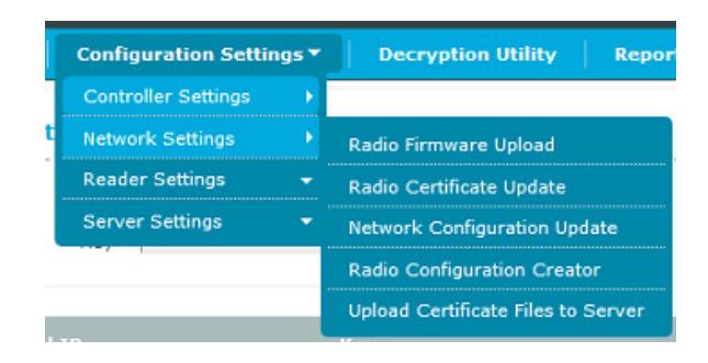
Radio Firmware Upload
This screen allows the user to upgrade the radio firmware on selected locks. This interface allows the user to upload radio firmware version for multiple locks at the same time. Locks with a GS1500 radio must have a radio configuration profile made for them before the firmware upgrade process. Please see "Radio Configuration Creator" on page 29 for instructions on how to do so.
The Radio Firmware Upload screen is accessible from Configuration Settings>Network Settings> Radio Firmware Upload .
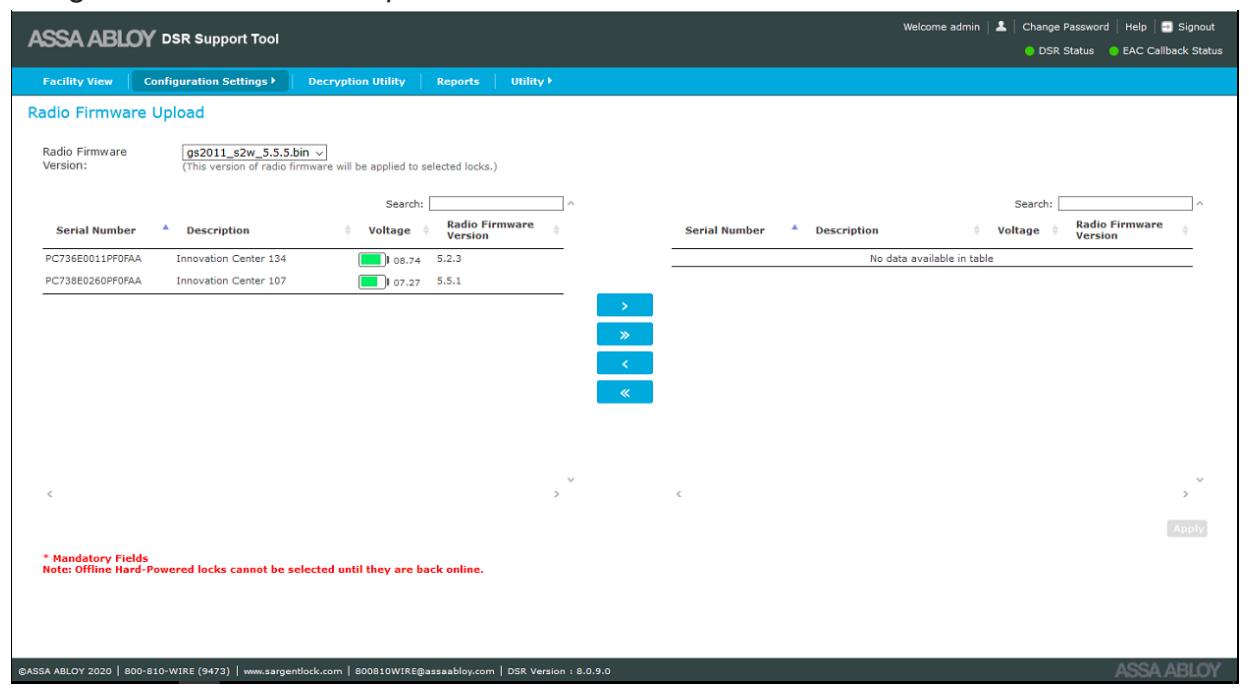
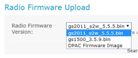
By default, the latest radio firmware version is selected in the Radio Firmware Version dropdown list. The latest version or any other available firmware version can be selected from the list. If DPAC Firmware Image is selected, then the controller firmware version is displayed next to the Radio Firmware Version dropdown list.


There are two panels on the Radio Firmware Upload screen:
- Left panel shows a list of all confirmed Sx/PX battery or external powered locks for which supports Over-the-Air radio firmware upgrade. Not all locks can accept a radio firmware upgrade. Details of the locks (description, voltage, and firmware version) are displayed along with the serial number in the left panel. Locks will be displayed based on the radio firmware version selected. Locks which have similar radio firmware version compared to selected radio firmware version will not be displayed on the screen.
- Right panel shows the list of locks selected for radio firmware upload.
To select a lock for firmware upload, select the desired lock in the left panel and click the > button. To select all of the locks, click the >> button.
To remove a lock from the firmware upload list on the right panel, select the desired lock and click the < button. To remove all of the locks from the upload list, click the << button.
When all of the desired locks are in the right panel, click the Apply button. If there are no locks listed in the right panel, the Apply button is disabled.
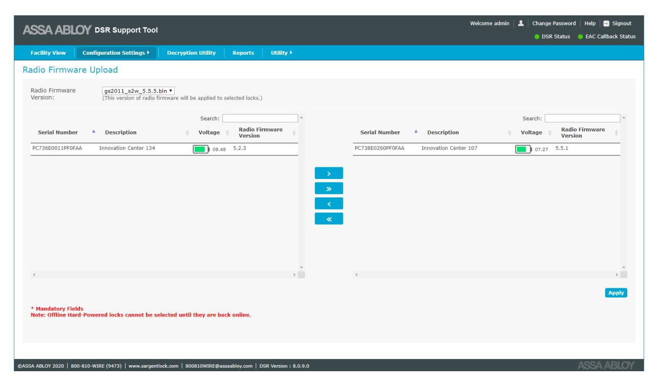
A message prompt appears on the screen with a notification of the firmware upgrade. Each lock selected will be upgraded on its next session. Once a lock begins its download, the process will take several minutes, during which time the lock will be unresponsive.
NOTE: DAPC radio cannot be downgraded to a lower version. GS2011 and GS2015 can be downgraded to a lower version. GS1500 can be downgraded, but this should only be done when directed by technical support.

Radio Certificate Update
This screen allows the user to update the network certificates of the locks over-the-air. Network certificates are uploaded using the Upload Certificate Files to Server screen. ( "Upload Certificate Files to Server" on page 30) . The Radio Certificate Update screen is used to select the certificate that will be used to update the locks. This can be done as a bulk update process.
This feature is only available for certain models of lock radios. Please consult technical support for help determining if the lock(s) have a supported radio. Also, the firmware version must be 3_0p04_v1883 or higher.
The Radio Certificate Update screen is accessed from Configuration Settings>Network Settings>Radio Certificate Update .
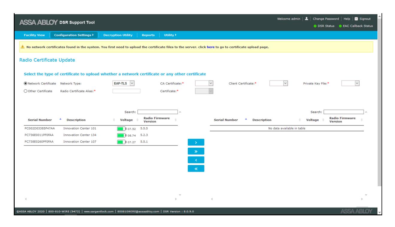
For battery powered locks, after applying the radio certificates it may be desirable to manually bring the lock online to start the process early. If this is not done, the radio certificate update commands are executed whenever the lock next comes online. The status of the radio certificate update can be seen on the Lock Details sub-tab.

Network Configuration Update
This screen allows the user to change network parameters for GS1500 and GS2011 locks only.
When a lock is configured for the first time, network parameters are pushed through LCT (Lock Configuration Tool). After that initial configuration, the lock's network settings can be adjusted through this tool.
The Network Configuration Update screen is accessible from Configuration Settings>Network Settings> Network Configuration Update .
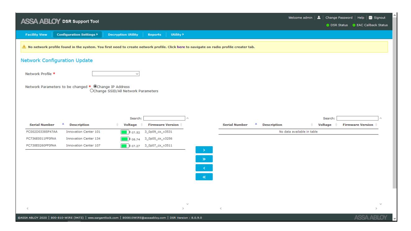
In the Network Profiles dropdown list all of the Radio Configuration profiles are displayed. These are the parameters which will be pushed to the locks. The user can choose to change either the IP Address or change all network parameters by selecting one of the two radio buttons.
Locks must be selected on the left panel and then using either the > or >> buttons, moved to the right panel. Changes are pushed to all locks listed in the right panel. As soon as the locks come online the new parameters are pushed. After the lock wakes up, the lock reports back with the new network configuration parameters.

Radio Configuration Creator
The Network Configurations screen is used to create network configuration required to perform a radio firmware upgrade for GS1500 radios and network configuration updates for GS1500 and GS2011 radios.
The Network Configurations screen is accessed from Configuration Settings>Network Settings>Radio Configuration Creator .
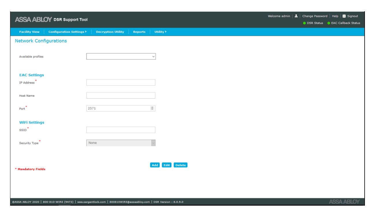
It is possible to add, edit, or delete a network configuration profile. The configuration profile for a lock should be identical to the configuration on the controller.

Upload Certificate Files to Server
The DSR Support Tool allows the user to update the network certificates of the locks over-theair. All of the network certificates nedd to be uploaded to the DSR server. The certificate size must be less than 4088 bytes (4KB).
The Upload Certificate screen is accessed from Configuration Settings>Network Settings> Upload Certificate Files to Server .
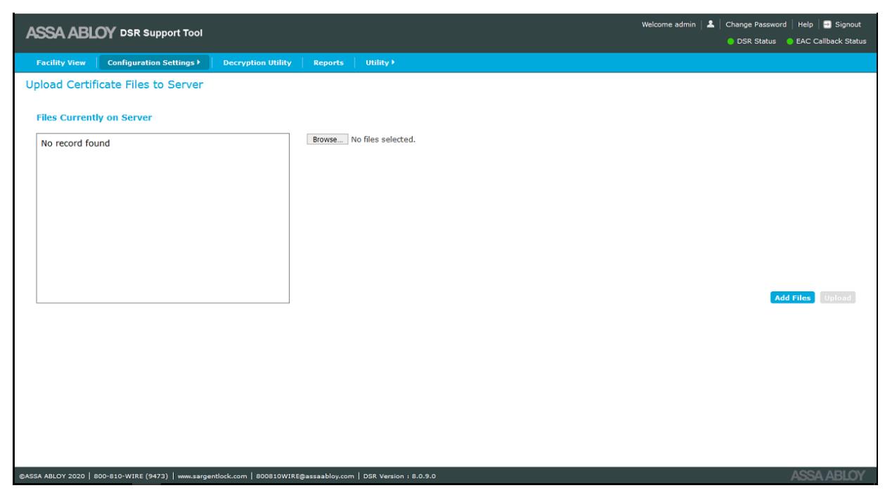
Users can choose the files for uploading. When uploads are complete, a confirmation message is displayed.

Reader Settings
This selection allows the user to set Reader Configuration, perform Reader Files Update, and Upload Reader Files (apdu) to Server.
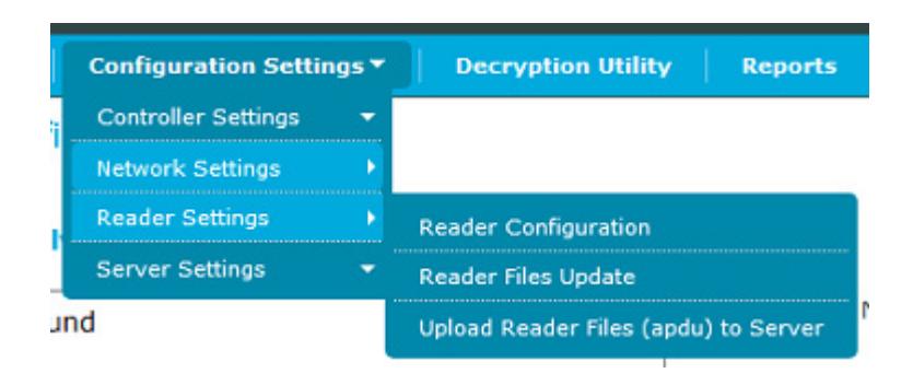
Reader Configuration
The Reader Configuration screen allows the user to enable/disable activity indicator on a reader having BLE card types selected over-the-air.
The Reader Configuration screen is accessed from Configuration Settings>Reader Settings> Reader Configuration .
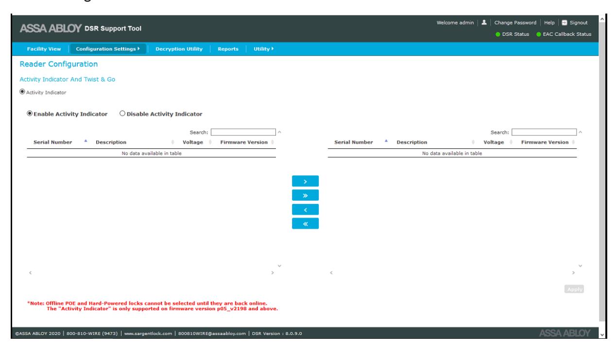
There are two panels on the Reader Configuration screen:
-
Left panel shows a list of all locks. Details of the locks (description, voltage, and firmware version) are displayed along with the serial number in the left panel.
- Locks will be displayed based on the radio firmware version selected. Locks which have similar radio firmware version compared to selected radio firmware version will not be displayed on the screen.
- Right panel shows the list of locks selected for enabling/disabling the activity indicator.

To select a lock for this action, select the desired lock in the left panel and click the > button. To select all of the locks, click the >> button.
To remove a lock from the list on the right panel, select the desired lock and click the < button. To remove all of the locks from the upload list, click the << button.
When all of the desired locks are in the right panel, click the Apply button. If there are no locks listed in the right panel, the Apply button is disabled.
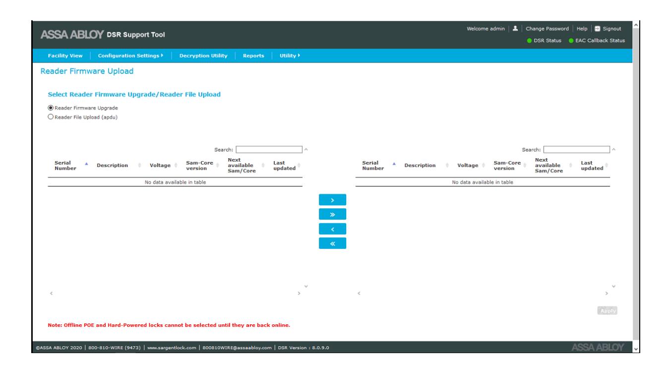
Reader Files Update
The Reader Files Update screen allows the user to upload reader firmware and upload reader files (apdu) to locks.
The Reader Files Update screen is accessed from Configuration Settings>Reader Settings> Reader Files Update .

Upload Reader Files (apdu) to Server
The Upload Reader Files to Server screen allows the user to upload the reader files to SE32\ ReaderFiles inside the DSR home directory. This should only be done under the direction of technical support for rare and site specific reader configuration.
The Reader Configuration screen is accessed from Configuration Settings>Reader Settings> Upload Reader Files (apdu) to Server .
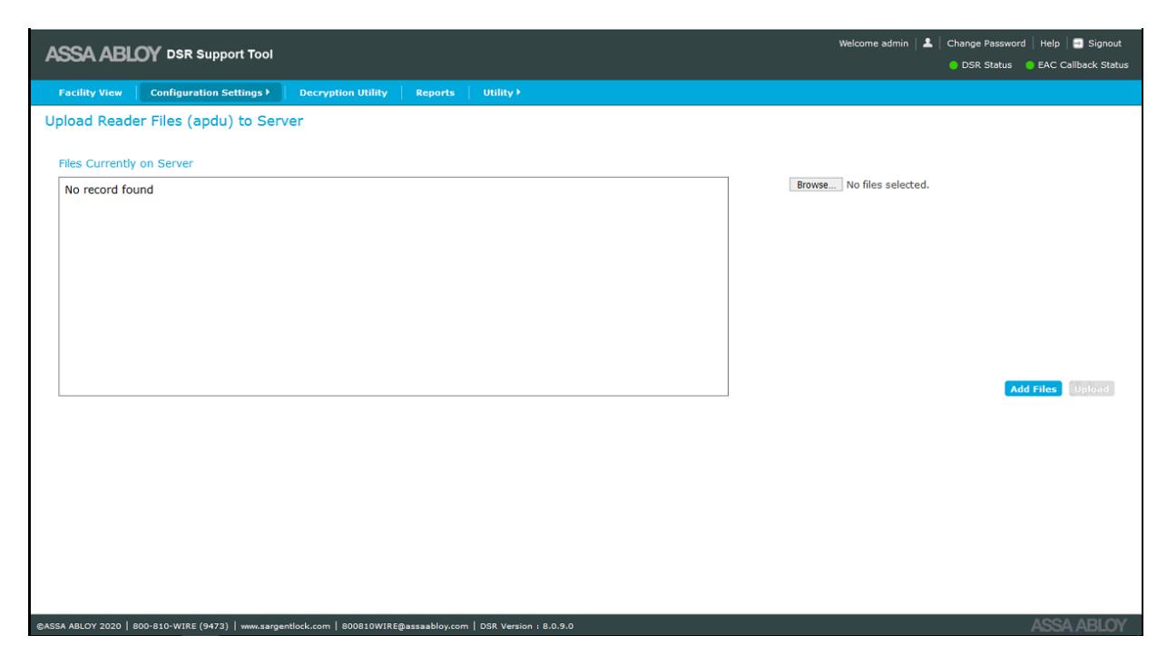
When this screen loads, any files currently in the SE32\ReaderFiles directory are displayed.
To add files, click the Browse button to search for the .apdu files desired. When selected, click the Add Files button to create an upload list. Multiple files can be selected and uploaded at one time.
To upload the selected files to the server, click the Upload button.
Only files with a .apdu extension can be uploaded. If any file with a different extension is uploaded, an error message appears. When the files are successfully uploaded, a success message is displayed.

Server Settings
This selection allows the user to enable or disable the WS Encryption and change the Port Configuration. These changes should be made in accordance with the documentation/guidance of the access control software provider.
NOTE: Changes made here will NOT take effect until the DSR service is restarted.
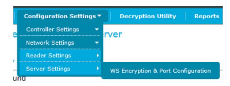
WS Encryption and Port Configuration
The WS Encryption and Port Configuration screen allows the user to modify WS-Encryption, SSL-Encryption, Access port, Lock port, Event port, and Security Valve. The initial settings are picked from DSR.
The WS Encryption & Port Configuration screen is accessed from Configuration Settings>Server Settings> WS Encryption & Port Configuration .
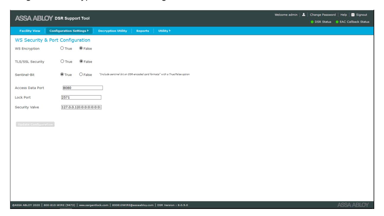
- WS-Encryption: this is used to encrypt the web-service data
- TLS/SSL Security: this is used to enable HTTPS communication, the default port is 8443
DSR Support Tool User Manual

- Sentinel-Bit: determines whether the lock include the sentinel bit when reading a credential. Not all credentials have sentinel bits. Please check with your EAC provider whether this setting should be enabled.
- Access Data Port: this is the access data port (default 8080 for http, default 8443 for https) where DSR is running and used by the Access Control Software to push the data
- Lock Port: this port is opened in DSR for communication with the lock
- Event Port: this is used for event retrieval (default 9001), it is opened in the DSR adapter for communication with the RA version of DSR to send the callback events
- Security Valve: this is a list of IP Addreses, where the support tool can be accessed to add new IP addresses. Use a | before the IP address. IP addresses not listed here will not be able to load the Support Tool. By default, the Support Tool can only be accessed locally.
To make changes to any of the settings, enter the desired change(s), then click the Update Configuration button.
For the RA version of the DSR installer, a pop-up message appears "DSR configuration has been updated and DSR service is stopped. Please start the DSR service and do same change in OEM system also!" Once the user clicks the OK button in the message pop-up, the DSR service is stopped. The service needs to be started manually.
For the standard, non-RA version of the installer, a pop-up message appears "DSR configuration has been updated and DSR service is stopped. Please start the DSR service."
NOTE:
- Access Data Port, Lock Port, and Event Port cannot be the same.
- Port range should be between 1025 and 65535.
WARNING: Encryption, sentinel-bit, and port settings (excluding Lock port) of the DSR MUST match the Access Control Software for the system to function. DO NOT change these settings unless directed to do so by the Access Control Software provider.

Reports
The Reports screen allows the support team to generate reports for battery usage. Reports can be viewed for multiple access points for a selected date range. The generated output report can be printed using the Print button, or can be saved in HTML and PDF formats. It is also possible to export the data as a CSV, fixed width, or XML file.
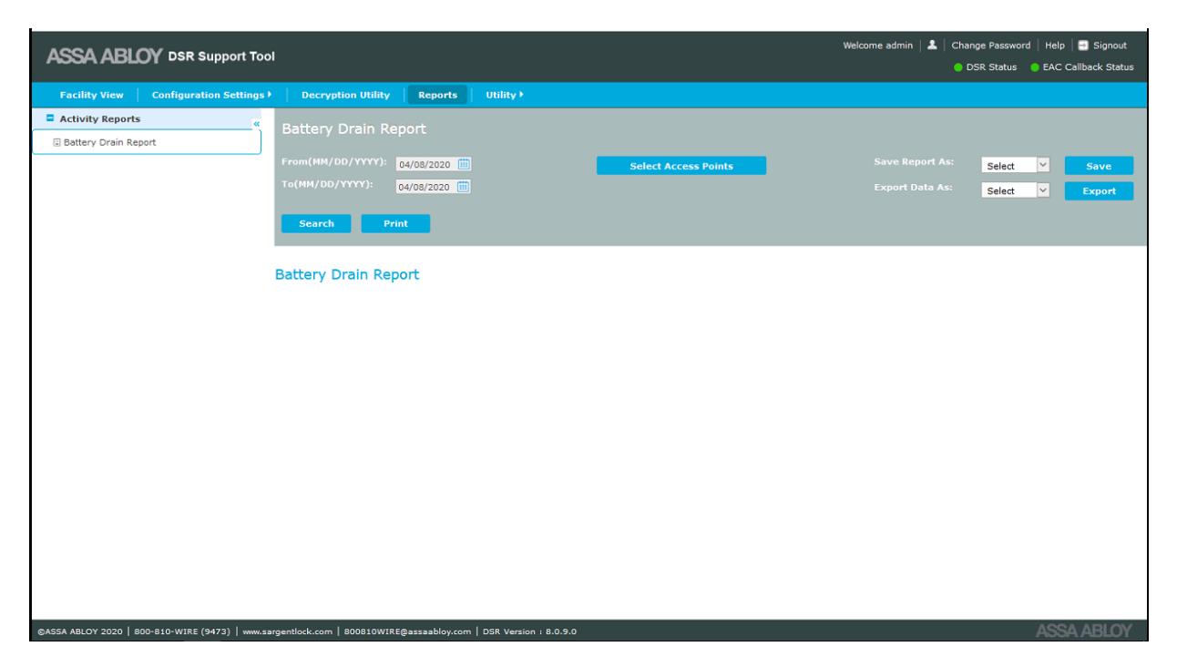
Click the Select Access Points button to select the desired access points to see in the report. Select the desired date range using the From and To calendar date fields.

Email & Battery Report Configuration
This selection allows the user to configure the battery replacement report.
The Email & Battery Report Configuration screen is accessed from Utility>Email & Battery Report Configuration .
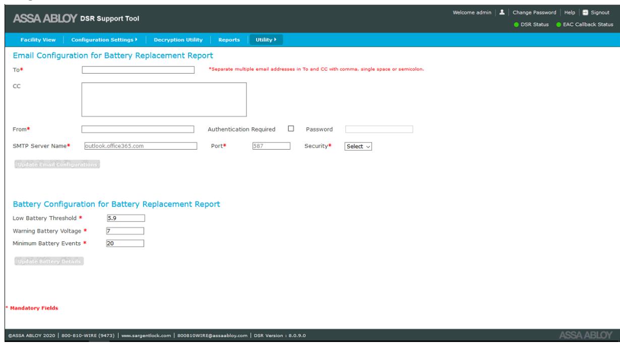
There are two parts to this screen, Email Configuration for Battery Replacement Report and Battery Configuration for Battery Replacement Report.
Email Configuration for Battery Replacement Report
This section requires email address information for at least one person where the battery replacement report is sent. All fields marked with a red asterisk are mandatory. The To and CC fields can have multiple email addresses separated by a comma, single space, or semicolon. Fill in all fields and then press the Update Email Configuration button.
Battery Configuration for Battery Replacement Report
This section requires the settings for low battery threshold value, warning battery voltage and minimum battery event that will trigger the battery replacement report email.
- Low Battery the batteries have reached a critical voltage level that may affect daily operations
- Warning Battery Voltage the batteries have reached a voltage level the is inappropriate for daily operations
- Minimum Battery Events the minimum battery voltage events required to forecast the battery life
When all setting are made, click the Update Battery Detail button.

Advanced Troubleshooting Tools
Decryption Utility
The Decryption Utility allows a support team to decrypt the cardholder credentials for troubleshooting purposes. The support team can generate the debug tables from this interface by entering the serial number of a lockset. Two debug tables are then created in the DSR database, which contain decrypted cardholder information. The Decryption Utility is accessed by clicking the Decryption Utility tab at the top of the screen
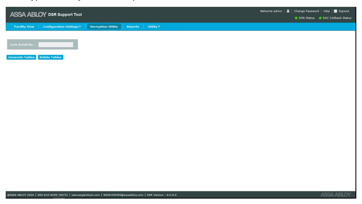
To decrypt cardholder credentials, do the following:
- 1. On the Decryption Utility screen enter the lock serial number in the Lock Serial No. field.
- 2. Click the Generate Tables button. Two debug tables are created in the database and a success message is displayed.
- 3. Open the database to view the debug tables:
debug_assaabloy_core_usercredential
debug_assaabloy_ipr3_sargentuser
When finished using the debug tables, click the Delete Tables button to delete the debug tables.

Logging Utility
This selection allows the user to enable/disable additional levels of logging for troubleshooting purposes.
The Enable Logging screen is accessed from Utility>Logging Utility .
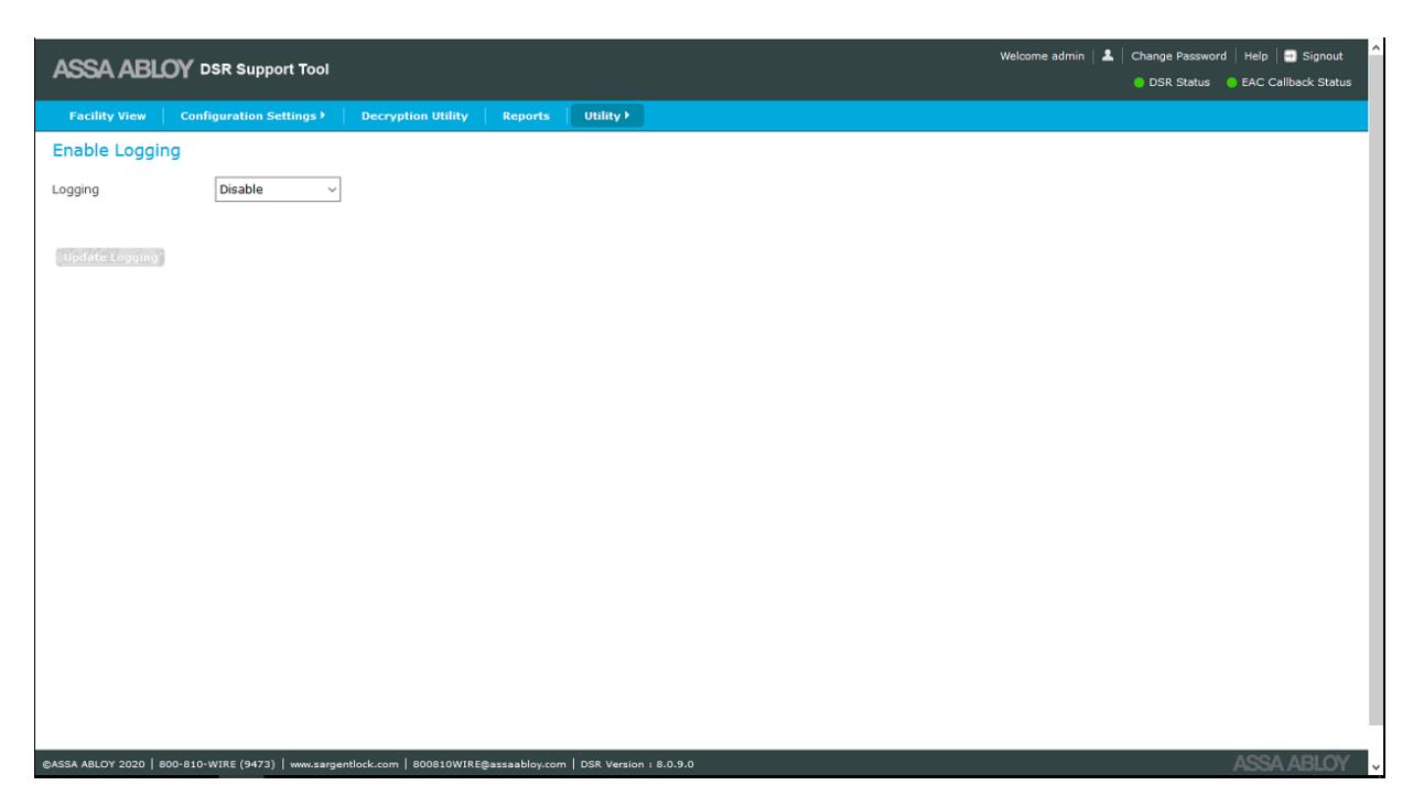
To enable or disable logging, select Enable or Disable from the Logging dropdown. Click the Update Logging button after selecting from the dropdown. A pop-up message appears stating the DSR service must be restarted manually for logging changes to take effect.

Download Lock Image
To download a lock image, select Advanced Operations. This selection allows the user to take a NVRAM backup for the controller. This file can be used by technical support for advanced troubleshooting.
The NVRAM Image Backup screen is accessed from Utility>Advanced Operations>NVRAM Image Backup .
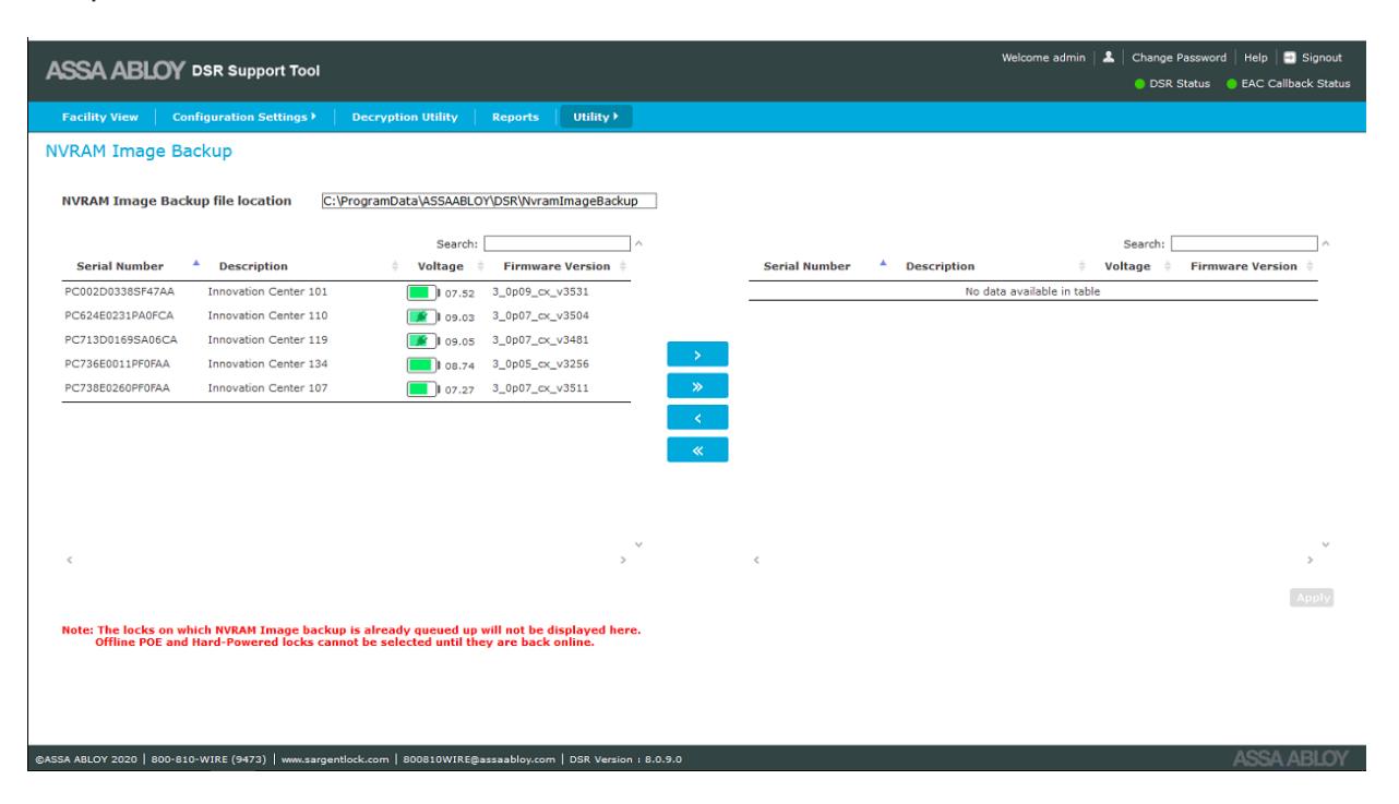
To take an NVRAM image backup, do the following:
- 1. Select a lock, or multiple locks, from the left panel.
- 2. Click the > button to move the locks to the right panel.
- 3. Select the desired lock from the right panel.
- 4. Click the Apply button. The NVRAM Image backup is stored in the path:
C:\ProgramData\ASSAABLOY\DSR\NvramimageBackup
DSR Support Tool User Manual

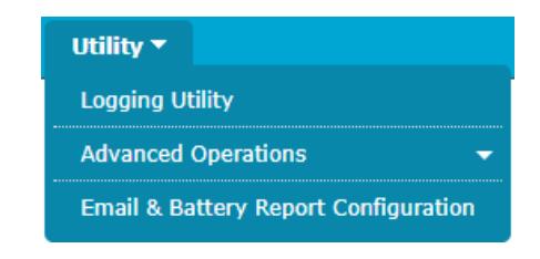
Utility
The Utility tab allows the user to use different utility functions to perform tasks such as logging, advanced operations and report configuration. See "Reports" on page 36 for the Email & Battery Report Configuration option. See "Advanced Troubleshooting Tools" on page 38 for the Logging Utility and Advanced Operations options.
ASSA ABLOY Americas 110 Sargent Drive New Haven, CT 06511 USA www.assaabloy.com