ASSA ABLOY ACCENTRA inTouch Stand-alone Touchscreen Access Cylindrical Lock Installation_80-9150-0075-010
Open the original PDF document
View PDF

inTouch®
Stand-alone Touchscreen Access Cylindrical Lock Installation and Programming Instructions
NOTE TO INSTALLER
FAILURE TO FOLLOW THESE INSTRUCTIONS COULD RESULT IN DAMAGE TO THE PRODUCT AND COULD VOID THE FACTORY WARRANTY
For Technical Assistance call Yale at 1-800-810-WIRE (9473)
This document is available on our website in Spanish and French. Go to www.yalelocks.com. Click "Product Information & Documentation" and then "Installation Instructions".
Este documento está disponible en español en nuestra página de internet. Vaya a www.yalelocks.com. Presione "Información del Producto y Documentación" y luego "Instrucciones de Instalación".
Ce document est disponible sur notre site Web dans le français imprimé. Allez à www.yalelocks.com. Cliquez sur le "; Information sur le produit et Documentation" et puis " Installation Instructions".
TABLE OF CONTENTS
| Warnings | 2 |
|---|---|
| Introduction | 2 |
| Installation | |
| Components and Tools | 3 |
| Door Preparation | 4 |
| Prepare Lock for Installation | 5-6 |
| Install Lock | 7-8 |
| Hardware Troubleshooting | 8 |
| Programming | |
| Programming Features-Menus-Keys-Definitions | 9-11 |
| Operation | 12-14 |
| Miscellaneous Information | 14 |
| Programming Troubleshooting | 15 |
| Sample Pin Code Management Sheet | 16-19 |
WARNINGS
CAUTION: Changes or modifications to this unit not expressly approved by the party responsible for compliance could void the user's authority to operate the equipment.
IMPORTANT: The accuracy of the door preparation is critical for the proper functioning and security of this cylindrical product. Misalignment can cause premature wear and a lessening of security.
Finish Care: This lockset is designed to provide the highest standard of product quality and performance. Care should be taken to ensure a long-lasting finish. When cleaning is required use a soft, damp cloth. Using lacquer thinner, caustic soaps, abrasive cleaners or polishes could damage the coating and result in tarnishing the finish.
Attention Installer: Any retrofit or other field modification to a fire rated opening can potentially impact the fire rating of the opening, and Yale Locks & Hardware makes no representations or warranties concerning what such impact may be in any specific situation. When retrofitting any portion of an existing fire rated opening, or specifying and installing a new fire-rated opening, please consult with a code specialist or local code official (Authority Having Jurisdiction) to ensure compliance with all applicable codes and ratings.
INTRODUCTION
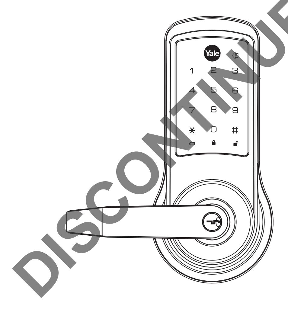
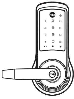
Yale® inTouch® Stand-alone Touchscreen Access Lock combines robust cylindrical locksets with a contemporary electronic aesthetic.
Users benefit from an interactive touchscreen that makes day-to-day access effortless and offers voice-guided programming for simple updates to user information in the event of staffing changes or security breaches.
inTouch is engineered for quick & easy installation and fits into the standard ANSI/BHMA A156.115 cylindrical locks with lever door prep with only one additional 3/4" hole and 7 screws including latchbolt and strike.
INSTALLATION
COMPONENTS AND TOOLS
In the box, you should find. . .
Quick Start Instructions
Installation Instructions
Door Marker
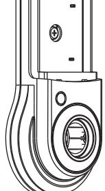
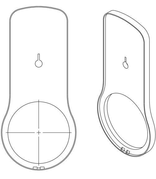
Outside Touchscreen Assembly
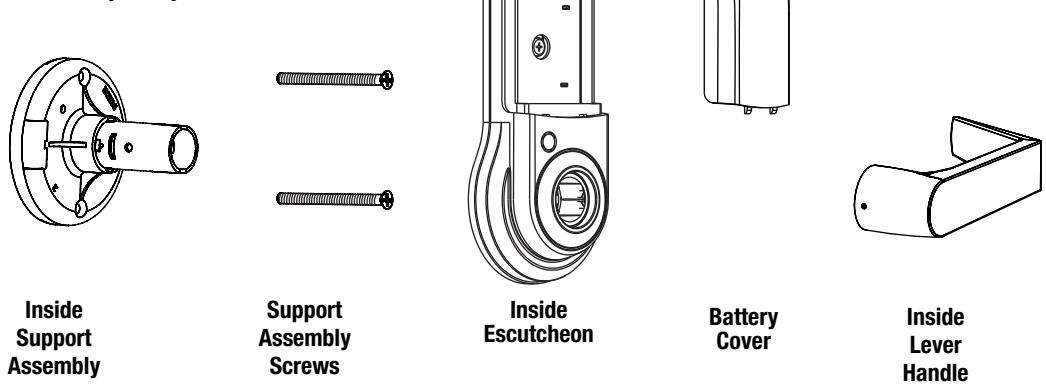
Inside Escutcheon Assembly:
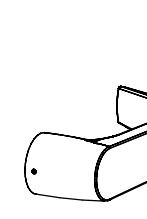
• Inside Support Assembly
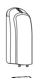
• Inside Escutcheon
• Inside Lever Handle
• Battery Cover
4 AA Alkaline Batteries
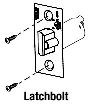
Latchbolt
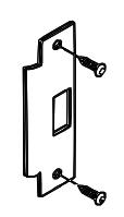
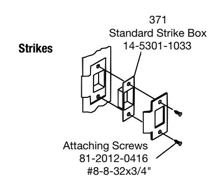
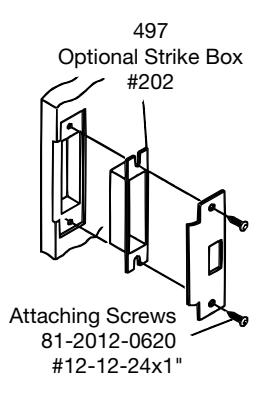
Strike
Allen Wrench 3/32" (2.5mm)
Lever Removal Tool
Screw Pack (7 screws)
2 Keys (If cylinder included)
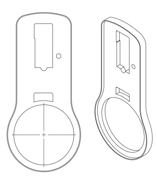
Parts Illustrations
Outside Touchscreen Assembly
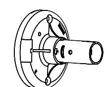
Inside Support Assembly
Inside Escutcheon
Inside Lever Handle
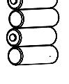
Battery Cover 4 AA Alkaline Batteries
Strike
Tools
Door Prep
- 2-1/8" (54mm) hole saw
- 1" (26mm) boring bit •
- 3/4" (19mm) drill bit
- 5/16" (8mm) drill bit •
- 7/64" (2.5mm) drill bit •
- Chisel & hammer •
- 3/8" or 1/2" drill
Lock Installation
- #2 phillips screw driver •
- Lever removal tool (supplied) •
- 3/32" Allen wrench (supplIed) •
DOOR PREPARATION
Mark Door
VerIfy backset before marking and drilling door.
- A. Mark horizontal line across edge of door at desired lever installation height.
- B. Fold door marker over the edge of the door, centering on the horizontal line.
- C. Mark centers of holes at proper backset. For beveled and square edge doors, mark both sides of the door.
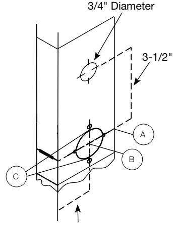
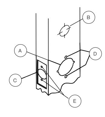
Drill Door
-
A. Drill 2-1/8" (54mm) dia. hole through the door. Cut notches as shown on template.
- Note: To avoid splintering wood doors, drill holes (A), (B) and (D) from both sides of the door.
- B. Drill 3/4" (19mm) diameter hole through the door according to door marker. (See note above.)
- C. Drill 1" (25mm) diameter hole in edge of door. Mortise for latchbolt front 1-1/8" (29mm) wide x 2-1/4" (57mm) high by 5/32" deep.
- D. Drill two (2) 5/16" (8mm) diameter holes through door (see note, above).
- E. Drill pilot holes for latchbolt screws. 7/64" (2.5mm).
Prepare and Install Strike (Wood Frames Only)
- A. Close the door and mark a horizontal line from the center of the template to the frame of the door.
- B. Measure half the thickness of the door. Mark this same distance with a vertical line starting from the stop side of the frame. Where both lines cross make a 1" (25mm) diameter hole, 1/2" (13 mm) in depth.
- C. Align the holes of the strike with the vertical line. Trace the outline of the strike and mortise with a 1/16" (1.6mm) depth. Attach the strike with two screws (provided).
Backset 2-3/4"
PREPARE LOCK FOR INSTALLATION
Unpack the Lock
The lock is packed representative of how it will install on the door.
Before installation:
- A. Disassemble the inside escutcheon
- 1. Remove the inside lever with the lever removal tool provided
- 2. Separate the inside support assembly from the inside escutcheon
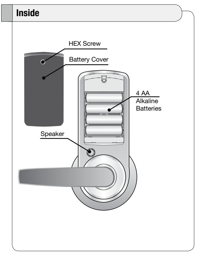
- B. Remove the battery cover
- 1. Unscrew the hex screw using the Allen wrench provided. The hex screw does not come completely out.
- 2. Slide the battery cover off.
The outside assembly stays assembled.
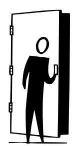
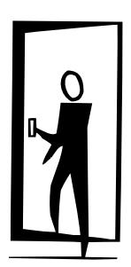
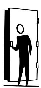
Determine Hand of the Door
Face the door from the secure side to determine it's hand.
The secure side is the touchscreen side of an entrance door or the corridor side of a room door. Note: inTouch locks are non-handed; the lever can be flipped around to the desired handing.
Left Hand Reverse Hinges on left. Opens outward. For handed locks, specify LHR.

Left Hand Hinges on left. Opens inward. For handed locks, specify LH.
Right Hand Hinges on right. Opens inward. for handed locks, specify RH.
Right Hand Reverse Hinges on right. Opens outward. For handed locks, specify RHR.
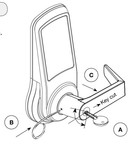
How to Replace, Re-Key or Install Cylinder
- 1. Remove cylinder handle:
- A. Insert key and rotate 45 degrees counterclockwise.
- B. Insert lever retainer tool and push.
- C. Slide lever off lock.
- 2. Remove the plastic sleeve from the old cylinder.
- 3. Slide new cylinder into sleeve.
- 4. Insert key into cylinder.
Important: Make sure the key cut side of key lines up facing towards the end of the lever. If the key is inserted incorrectly, the lock will reassemble and might appear to properly work; however, when the key is removed, the latchbolt will remain retracted.

Depress retainer plate, push the handle onto the shank until fully seated. Pull on handle to insure properly seated.
® CAUTION: For units shipped prior to March 2012: The cylinders furnished with inTouch lock for use in 1-3/8" doors have a tailpiece that is 1/4" shorter than the standard cylinders that are furnished for 1-3/4" doors. Trying to install a standard cylinder in locksets designed for 1-3/8" doors will DAMAGE the lock body.
Adjust for Door Thickness (If Necessary)
Lock is provided standard for use on 1-3/4" thick doors. For use on 1-3/8" thick doors, special thin door kit must be used. To order 1-3/8" thin door kit, specify part number 14-4761-0106. This kit includes inside and outside escutcheon spacers as well as a 2-3/8" latchbolt. Note: using a 2-3/8" latchbolt results in Grade 2 certification on the lock.

INSTALL LOCK
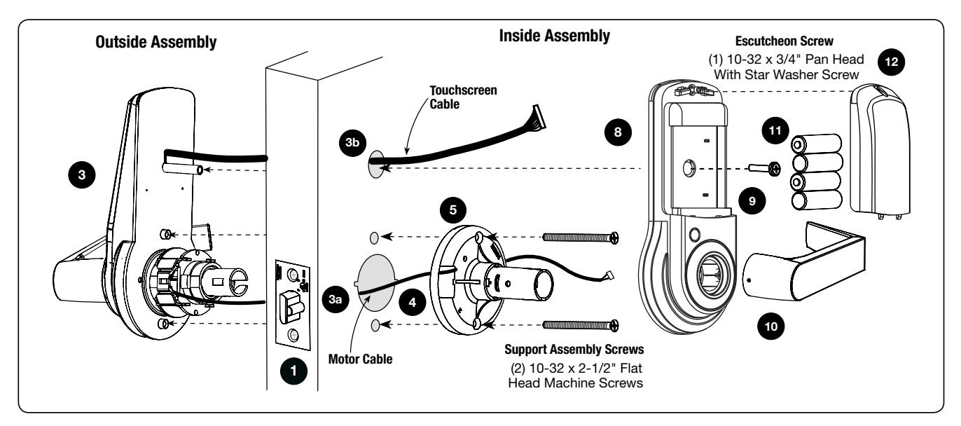
Directions
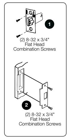
- 1. Install latchbolt in door. Be sure that bevel edge of bolt faces strike. Attach with two screws supplied.
- 2. Install strike on the door frame.
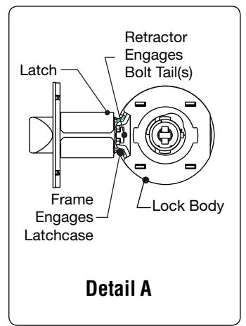
- 3. Insert outside assembly through door, making sure that the lock body frame hooks latch case and retractor engages bolt tail(s). DO NOT FORCE (See Detail A above). If lock body does not engage latch easily, check door preparation for errors.
- a. Guide motor cable (red and black wires) through 2-1/8" diameter hole.
- b. Guide touchscreen cable through 3/4" diameter upper hole.
- 4. Guide motor cable through rectangular hole on inside support assembly.
- 5. Slide inside support assembly over outside assembly, lining up top and bottom screw guides with holes in door. Secure both assemblies with (2) 10-32 x 2-1/2" flat head machine screws. Do not over-tighten.
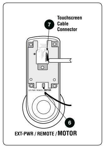
- 6. Attach motor cable connector to the inside escutcheon PC board header marked "MOTOR."
- 7. Attach the touchscreen cable connector to the inside escutcheon PC board header as illustrated.
Directions, Continued
8. Slide inside escutcheon over inside support assembly.
CAUTION :
- a. Position motor cable against inside support assembly. Avoid pinching wires against the steel shank of the assembly.
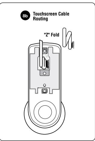
- b. "Z" fold touchscreen wire cable and lay against the back recessed area of the escutcheon assembly. Position and bend wires to prevent binding when installing the escutcheon over the support assembly.
- 9. Install and secure the 10-32 x 3/4" pan head screw through the center of the battery housing into the barrel nut of the outside assembly.
- 10. Slide on inside lever and push in to attach.
- 11. Insert four (4) AA alkaline batteries. The lock responds, " Welcome to the Yale Digital World ."
- 12. Install battery cover and tighten hex head screw with Allen wrench provided with lock.
HARDWARE TROUBLESHOOTING
Test the Operation of the Mechanical Lockset
Cycle the lock in both the locked and the unlocked positions. If problems are found:
| Symptom | Suggested Action |
|---|---|
| Door is binding | a. Check that door and frame are properly aligned and door is free swinging. |
| b. Check hinges: They should not be loose or have excessive wear on knuckles. | |
| Latchbolt will not deadlock |
a. Either strike is out of alignment or the gap between the door and jamb is too great.
Realign strike or shim strike out towards flat area of latchbolt. |
| Latchbolt does not retract or extend properly | Latchbolt tail and retractor are not properly positioned: |
|
a. Remove lockset. Look though 2-1/8" hole and verify latchbolt tail is centered
between top and bottom of hole. |
|
|
b. Remove latchbolt and insert lockset. Look though latchbolt hole and verify retractor
mouth centered in hole. If not, adjust outside rose plate. |
|
| c. If necessary, rebore holes to line up retractor and tail. |
PROGRAMMING
| Programming Features-Menus-Keys-Definitions9-11 | |
|---|---|
| Operation12-14 | |
| Miscellaneous Information14 | |
| Programming Troubleshooting15 | |
| Sample Pin Code Management Sheets16-19 |
PROGRAMMING FEATURES - MENUS - KEYS - DEFINITIONS
Menu and Icons
|
Touch the screen with palm of hand or
fingers to begin and end actions. |
M |
Enter Personalized Master PIN code
(6 digits in length). |
|
|---|---|---|---|
| ~ | Click the indicated number. | U | Enter User PIN. Can be 4-12 digits in length. |
|
Press the Star key on the touchscreen to
Enter or Accept entry. |
User Number (1 - 255). | ||
|
Press the Pound key on the touchscreen to
enter Menu mode. |
Enter value 1 - 10 (times or seconds). | ||
|
Press this key to return to the previous
step or menu setting. |
Enter value 1 - 255 (seconds). | ||
| Repeat operation using settings indicated. | |||
| Slide the battery cover up and off. | Voice guide. |
Definitions
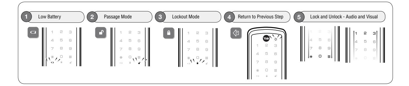
All Code Lockout : This feature is enabled only by the Master code. When all user PIN code access. When the unit is in Lockout, the red locked padlock will appear on the screen. enabled, it restricts
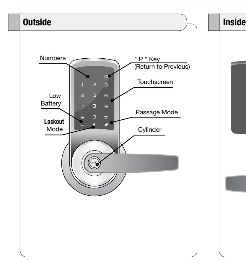
Low Battery : When battery power is low, the low battery icon will begin blinking. If battery power is completely lost, the key and cylinder can be used.
Passage Mode : Enabling Passage mode allows continuous entry for non-restricted traffic. Passage mode is enabled or disabled through feature programming by the Master code. When the unit is in Passage Mode, the green unlocked padlock will appear on the screen.
Master Code : The Master code is personalized by the user upon installation. There is no factory default. The Master code is used for programming User codes and feature settings. The Master code will operate the lock.
Definitions
Re-lock Time : After successful code entry and the unit unlocks, it will automatically re-lock after a default of five (5) seconds. Re-lock time is adjustable from one (1) to ten (10) seconds through feature settings.
Shut Down Time : The unit will shut down for a default of one hundred and eighty (180) seconds and not allow operation after the wrong code entry limit has been met. Shut down time is adjustable from one (1) to two hundred and fifty-five (255) seconds through feature settings. When the unit is in Shut Down, the red locked padlock icon will be flashing.
Silent Mode : Enabling Silent mode shuts off the code confirmation tone playback for use in quiet areas. Silent mode is enabled or disabled through feature code. programming by the Master
User Code : The User code is used for operating the lock.
User Lockout : This feature is enabled by the Master code. When enabled, it restricts User PIN code access only for the specified User numbers.
Wrong Code Entry Limit : After a default of five (5) unsuccessful attempts at entering a valid PIN code the unit will shut down and not allow operation. Wrong code entry limit is adjustable from one (1) to ten (10) times through feature settings.
OPERATION
® inTouch features single programming mode with a total of 255 PIN codes available for access. All programming is performed through the touchscreen by use of the Master code (which also grants access) and voice guided prompts.
The lock can be programmed for Passage mode, Silent mode, Lockout mode or alternate language settings. Auto re-lock time, wrong code entry limits and shut down times are adjustable can be changed from factory default.
| Settings | Master | User |
|---|---|---|
| Entrance Authorization | x | x |
| Register/Change Master Code | x | |
| Register/Change/Delete User Code | x | |
| Set All Code Lockout Mode | x | |
| Set User Lockout Mode | x | |
| Set Passage Mode | x | |
| Set Silent Mode | x | |
| Set Re-lock Time | x | |
| Set Wrong Code Entry Limit | x | |
| Set Shut Down Time | x | |
| Set Language Setting Mode | x |
| Settings | Factory Defaults |
|---|---|
| Master Code | User Personalized |
| Lockout Mode | Disabled |
| Passage Mode | Disabled |
| Silent Mode | Disabled |
| Re-lock Time | 5 Seconds |
| Wrong Code Entry Limit | 5 Times |
| Shut Down Time | 180 Seconds |
| Language | English |
Operation of Lock
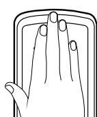
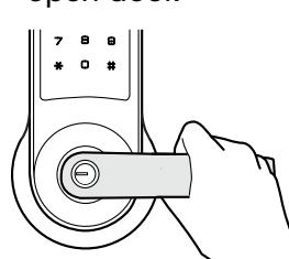
Touch lock with palm of hand or fingers to activate.
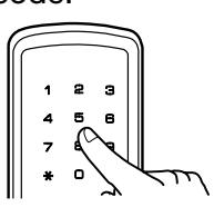
Enter the Master or a User PIN code.
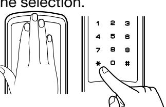
Palm touch the screen or press the key to confirm the selection.
Turn lever to open door.
Establish the Master Code Before Programming
- 1. Touch the screen with the palm of your hand or fingers to activate .
- 2. Press the key.
- 3. Enter personalized 6-digit Master PIN code followed by the key.
- 4. Press key to complete the process and conclude the programming session.
Feature Programming
- 1. Touch the screen with the palm of your hand or fingers to activate .
- 2. Enter the 6-digit Master PIN code followed by the key. Lock Response: " Menu mode, enter number, press the key to continue ."
- 3. Enter digit corresponding to the function to be performed followed by the key. Follow the verbal commands.
- 4. Press the key to complete the process and conclude the programming session.
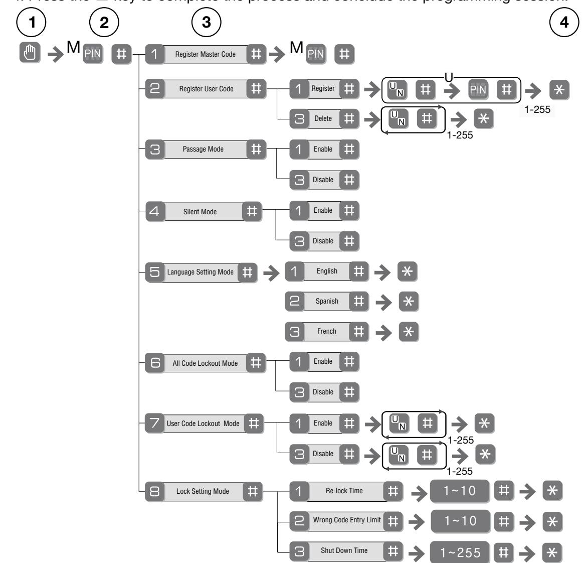
To Set Up User Codes
User Codes can only be programmed through Master Code.
- 1. Touch the screen with the palm of your hand or fingers to activate .
- 2. Enter the 6 digit Master PIN code followed by the key. Lock Response: " Menu mode, enter number, press the key to continue ."
- 3. Enter "2" followed by the key.
- 4. Enter "1" followed by the key.
- 5. Enter the User number to be registered (1-255) followed by the key.
- 6. Enter a 4-12 digit PIN code for the User number followed by the key. Press to add more users.
- 7. Press the key to complete the process and conclude the programming session.
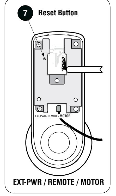
MISCELLANEOUS INFORMATION
Returning the Lock to Factory Defaults
The outside assembly remains assembled.
- 1. Remove inside lever with the lever removal tool.
- 2. Remove battery cover using Allen wrench provided with lock.
- 3. Remove four (4) AA alkaline batteries.
- 4. Remove the 10-32 x 3/4" pan head screw from the center of the battery housing into the barrel nut of the outside assembly.
- 5. Remove inside escutcheon.
- 6. Reinstall batteries four (4) AA alkaline batteries.
- 7. On the back of the PC board, push and hold the Reset Button with the lever removal tool for 3 seconds.
- 8. Temporarily remove one (1) AA battery (still holding the reset button in).
- 9. Reinstall the AA battery (still holding the reset button in).
- 10. Release reset button and wait 3 seconds.
- 11. The speaker will announce "Welcome to the Yale Digital World".
To reassemble the lock, refer to steps 8 through 12 on page 8. All programming should be returned to factory defaults.
PROGRAMMING TROUBLESHOOTING
| Symptom | Suggested Action |
|---|---|
|
Lock does not respond – door is
open and accessible. |
•
The touchscreen will become active when pressed with the palm or fingers in at least 3 areas simultaneously. |
|
•
Use a larger area of the palm or fingers and verify contact with at least 3 areas. |
|
|
•
If touchscreen numbers are visible, check to see if they respond when pressed. |
|
|
•
Check batteries are installed and oriented correctly in the battery case. |
|
|
•
Check batteries are in good condition; replace batteries if discharged. |
|
|
•
Check to see if touchscreen cable is properly connected and not pinched (page 7). |
|
| Lock does not respond – door is |
•
Batteries may be completely discharged. |
| locked and inaccessible. |
•
Use mechanical key to gain entry and replace batteries. |
|
The unit is on for a while, and then
shows no reaction. Lights dim. |
•
The batteries do not have enough power. Replace the batteries. |
| Unit chimes to indicate code accep |
•
Check to see if there is another locking device on the door (i.e. deadbolt). |
| tance, but the door will not open. |
•
Check the door gaps for any foreign objects between door and frame. |
|
•
Check that the motor cable is firmly connected to the PC board header marked "MO TOR" (page 7). |
|
| Unit operates to allow access, but will |
•
Check to see if Passage Mode is enabled. |
| not automatically re-lock. |
•
If the Passage Mode icon on the touchscreen and the status indicator on the |
| interior escutcheon flicker for several seconds, it is set at Passage Mode (page 10). | |
|
•
Disable Passage Mode to lock the door. |
|
|
•
If low battery indicator is lit (page 10), change batteries. |
|
| PIN codes will not register. |
•
PIN codes must consist of 4 to 12 digits to register. |
|
•
The same PIN code cannot be used for multiple users. |
|
|
•
Registration/management of PIN codes is set at the authority of the Master. |
|
|
•
Contact the Master. |
|
|
•
The Master PIN code does unlock the door. |
|
|
•
User codes must be entered within 20 seconds (while the touchscreen is active) or the process will have to be restarted. |
|
|
The star (∗) or pound (#) can not be used as part of the PIN code.
• |
|
| Upon entering a PIN code and press |
•
Either All Code or User Lockout Mode is enabled (pages 13). |
|
ing the star (∗) key, the unit displays
and "invalid code" error or the lock |
•
Only the Master can enable Lockout Mode. |
| times out without responding. |
•
Contact the Master user. |
| Upon entering a PIN code and press |
•
Check to see if you are set at Lockout Mode. |
|
ing the (∗) key, the red padlock icon
appears and there are different tones. |
•
Setting/managing Lockout Mode is up to Master. Contact the Master. |
|
The unit operates, but it makes
no sound. |
•
Check to see if Silent Mode is enabled (page 13). |
| The unit responds "Low Battery" |
•
This is the voice alarm alerting that it is time to replace the batteries. Replace all four (4) batteries with new AA Alkaline batteries. |
|
Upon entering a PIN code and press
ing the star (∗) key, the unit responds "Wrong digit numbers." |
•
The digits entered were incorrect or incomplete. Re-enter the code. |
| PIN Code Management | |||||
|---|---|---|---|---|---|
| Door Number: | Door Number: | ||||
| User Name | PIN Number | User Name | PIN Number | ||
| User 1 | User 41 | ||||
| User 2 | User 42 | ||||
| User 3 | User 43 | ||||
| User 4 | User 44 | ||||
| User 5 | User 45 | ||||
| User 6 | User 46 | ||||
| User 7 | User 47 | ||||
| User 8 | User 48 | ||||
| User 9 | User 49 | ||||
| User 10 | User 50 | ||||
| User 11 | User 51 | ||||
| User 12 | User 52 | ||||
| User 13 | User 53 | ||||
| User 14 | User 54 | ||||
| User 15 | User 55 | ||||
| User 16 | User 56 | ||||
| User 17 | User 57 | ||||
| User 18 | User 58 | ||||
| User 19 | User 59 | ||||
| User 20 | User 60 | ||||
| User 21 | User 61 | ||||
| User 22 | User 62 | ||||
| User 23 | User 63 | ||||
| User 24 | User 64 | ||||
| User 25 | User 65 | ||||
| User 26 | User 66 | ||||
| User 27 | User 67 | ||||
| User 28 | User 68 | ||||
| User 29 | User 69 | ||||
| User 30 | User 70 | ||||
| User 31 | User 71 | ||||
| User 32 | User 72 | ||||
| User 33 | User 73 | ||||
| User 34 | User 74 | ||||
| User 35 | User 75 | ||||
| User 36 | User 76 | ||||
| User 37 | User 77 | ||||
| User 38 | User 78 | ||||
| User 39 | User 79 | ||||
| User 40 | User 80 |
| PIN Code Management | |||||
|---|---|---|---|---|---|
| Door Number: | Door Number: | ||||
| User Name | PIN Number | User Name | PIN Number | ||
| User 81 | User 121 | ||||
| User 82 | User 122 | ||||
| User 83 | User 123 | ||||
| User 84 | User 124 | ||||
| User 85 | User 125 | ||||
| User 86 | User 126 | ||||
| User 87 | User 127 | ||||
| User 88 | User 128 | ||||
| User 89 | User 129 | ||||
| User 90 | User 130 | ||||
| User 91 | User 131 | ||||
| User 92 | User 132 | ||||
| User 93 | User 133 | ||||
| User 94 | User 134 | ||||
| User 95 | User 135 | ||||
| User 96 | User 136 | ||||
| User 97 | User 137 | ||||
| User 98 | User 138 | ||||
| User 99 | User 139 | ||||
| User 100 | User 140 | ||||
| User 101 | User 141 | ||||
| User 102 | User 142 | ||||
| User 103 | User 143 | ||||
| User 104 | User 144 | ||||
| User 105 | User 145 | ||||
| User 106 | User 146 | ||||
| User 107 | User 147 | ||||
| User 108 | User 148 | ||||
| User 109 | User 149 | ||||
| User 110 | User 150 | ||||
| User 111 | User 151 | ||||
| User 112 | User 152 | ||||
| User 113 | User 153 | ||||
| User 114 | User 154 | ||||
| User 115 | User 155 | ||||
| User 116 | User 156 | ||||
| User 117 | User 157 | ||||
| User 118 | User 158 | ||||
| User 119 | User 159 | ||||
| User 120 | User 160 |
| PIN Code Management | |||||
|---|---|---|---|---|---|
| Door Number: | Door Number: | ||||
| User Name | PIN Number | User Name | PIN Number | ||
| User 161 | User 201 | ||||
| User 162 | User 202 | ||||
| User 163 | User 203 | ||||
| User 164 | User 204 | ||||
| User 165 | User 205 | ||||
| User 166 | User 206 | ||||
| User 167 | User 207 | ||||
| User 168 | User 208 | ||||
| User 169 | User 209 | ||||
| User 170 | User 210 | ||||
| User 171 | User 211 | ||||
| User 172 | User 212 | ||||
| User 173 | User 213 | ||||
| User 174 | User 214 | ||||
| User 175 | User 215 | ||||
| User 176 | User 216 | ||||
| User 177 | User 217 | ||||
| User 178 | User 218 | ||||
| User 179 | User 219 | ||||
| User 180 | User 220 | ||||
| User 181 | User 221 | ||||
| User 182 | User 222 | ||||
| User 183 | User 223 | ||||
| User 184 | User 224 | ||||
| User 185 | User 225 | ||||
| User 186 | User 226 | ||||
| User 187 | User 227 | ||||
| User 188 | User 228 | ||||
| User 189 | User 229 | ||||
| User 190 | User 230 | ||||
| User 191 | User 231 | ||||
| User 192 | User 232 | ||||
| User 193 | User 233 | ||||
| User 194 | User 234 | ||||
| User 195 | User 235 | ||||
| User 196 | User 236 | ||||
| User 197 | User 237 | ||||
| User 198 | User 238 | ||||
| User 199 | User 239 | ||||
| User 200 | User 240 |
| PIN Code Management | |||||
|---|---|---|---|---|---|
| Door Number: | |||||
| User Name | PIN Number | ||||
| User 241 | |||||
| User 242 | |||||
| User 243 | |||||
| User 244 | |||||
| User 245 | |||||
| User 246 | |||||
| User 247 | |||||
| User 248 | |||||
| User 249 | |||||
| User 250 | |||||
| User 251 | |||||
| User 252 | |||||
| User 253 | |||||
| User 254 | |||||
| User 255 | |||||