ASSA ABLOY ACCENTRA eBOSS E5400LN Cylindrical Keypad Lock (Product Discontinued October 1, 2012_80-9150-8004-010
Open the original PDF document
View PDFYale E5400LN
Cylindrical Keypad Lock
Installation Instructions
80-9150-8004-010 Rev. D
NOTE TO INSTALLER
FAILURE TO FOLLOW THESE INSTRUCTIONS COULD RESULT IN DAMAGE TO THE LOCK AND VOID THE FACTORY WARRANTY.
e · · · boss
Electronic Battery Operated Security Solution
FEATURES
- Battery Operated (Hardwire Capable) Motorized Grade 1 Cylindrical Lock
- 94 User Code Capacity
- All Metal Escutcheon and Pushbuttons
- LED Function Indicator
- 5400LN Patented Free-Wheeling Levers
- Weather Resistant, ADA Compliant 12-Button Keypad
- Modular Design (Simple Installation)
- Audible Pushbutton
- Patent Pending Keypad Blinders
- Request to enter input
- Emergency, Supervisor, Passage, Lockout and Master Codes
Operational Modes
Secure
Normal locked state. Any assigned user code can gain access. Lock/relocks automatically.
Lockout
Lockset will not accept any assigned user codes except for the Supervisor and Emergency Codes.
<u>Passage</u>
Maintains unlocked state. Relocks by entering passage code the second time
Finish Care
This lockset is designed to provide the highest standard of product quality and performance. Care should be taken to insure a long-lasting finish. When cleaning is required use a soft, damp cloth. Using lacquer thinner, caustic soaps, abrasive cleaners or polishes could damage the coating and result in tarnishing,
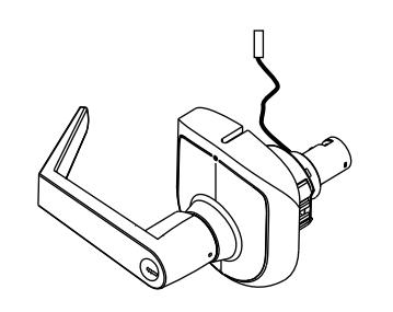
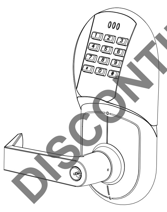
OUTSIDE LOCK CHASSIS
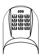
KEYPAD ASSEMBLY
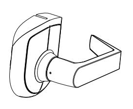
INSIDE LEVER ASSEMBLY
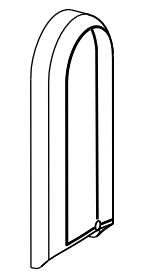
INSIDE ESCUTCHEON ASSEMBLY
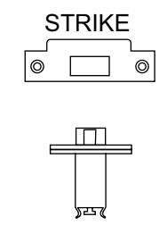
LATCHBOLT
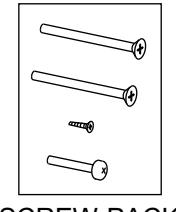
SCREW-PACK 1
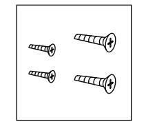
SCREW-PACK 2
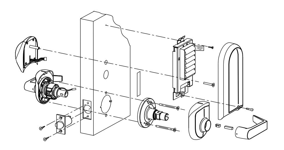
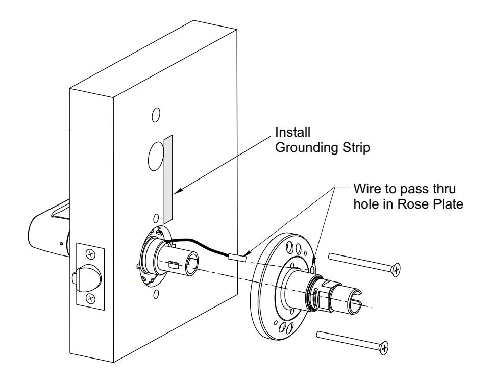
GROUNDING STRIP (See Template)
| Table of Contents | Page |
|---|---|
| Section I Prepare the Door | 3 |
| I-A Prepare the Door for Lock Body & Latch | 3 |
| I-B Locate and Drill Holes for Electronic Components | 4 |
| Section II Prepare Lock for Installation | 4 |
| II-A How to Change Hands (Standard Cylinder Locks) | |
| II-B How to Change Hands (Interchangeable Core Cylinder and | |
| Non Cylinder Locks) | 5 |
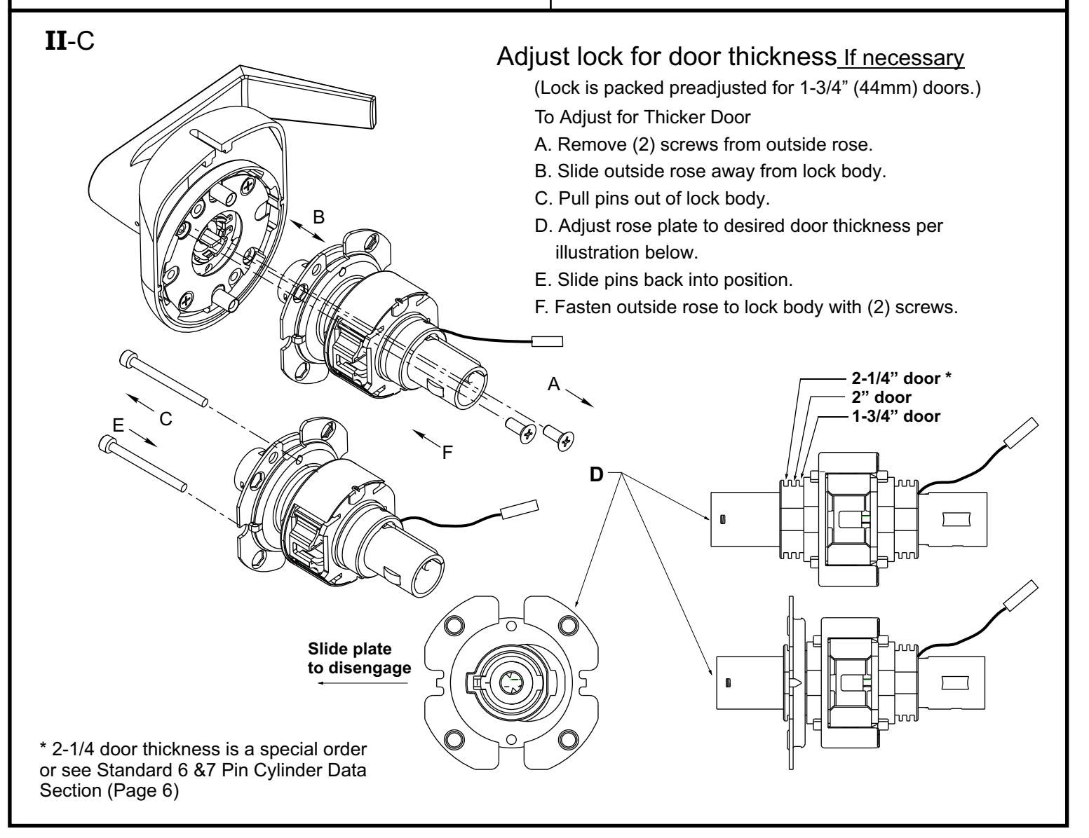
| II-C Adjust lock for door thickness If necessary | 5 |
| II-D Re-Keying/Competitor Cylinder | 6 |
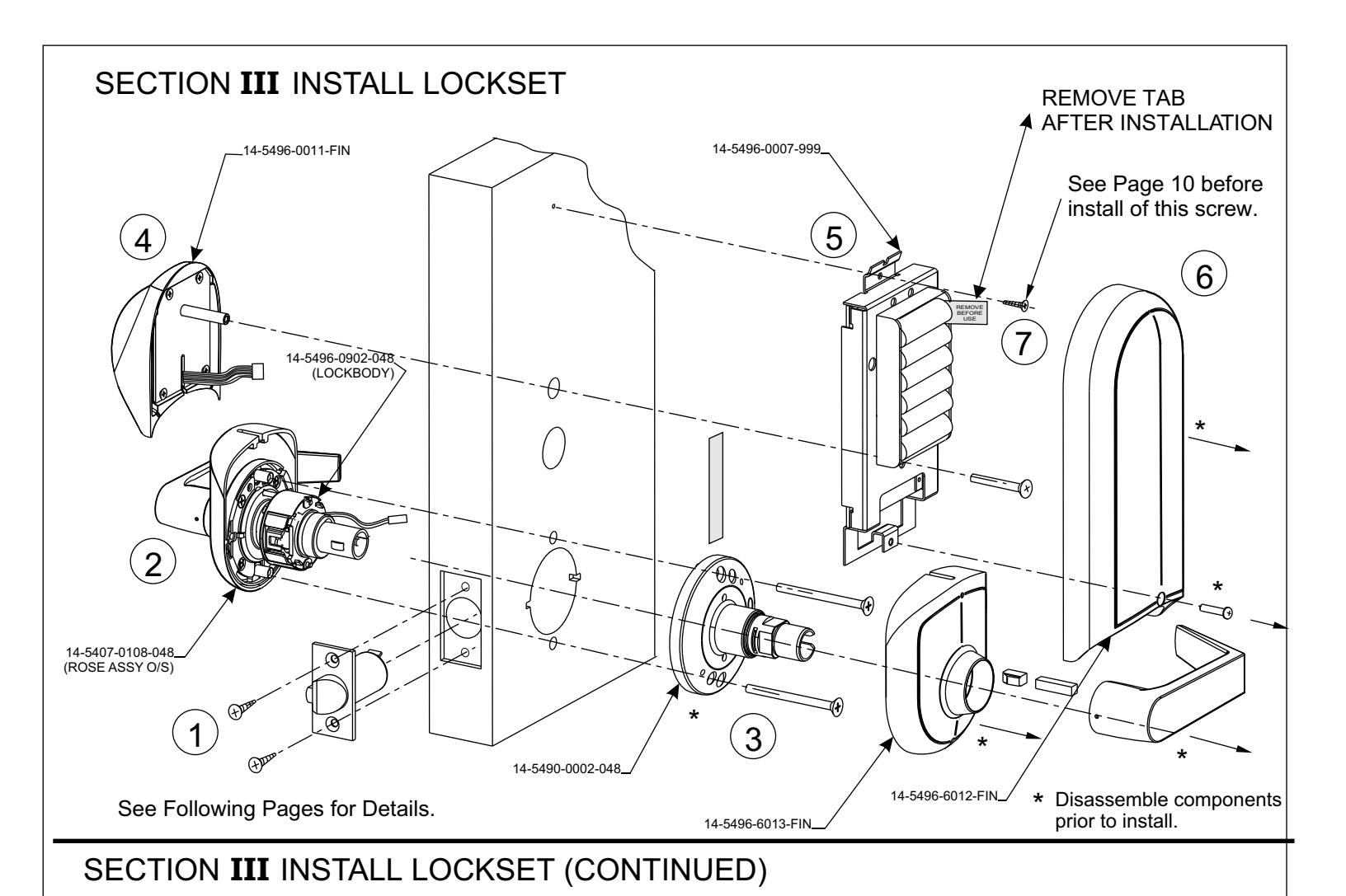
| Section III Install Lockset | 7 |
| III-A Install Mechanical Components | 7 |
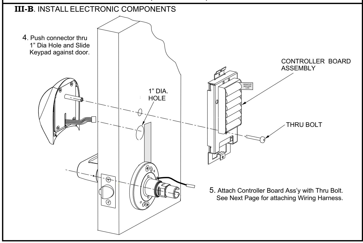
| III-B Install Electronic Components | 8 |
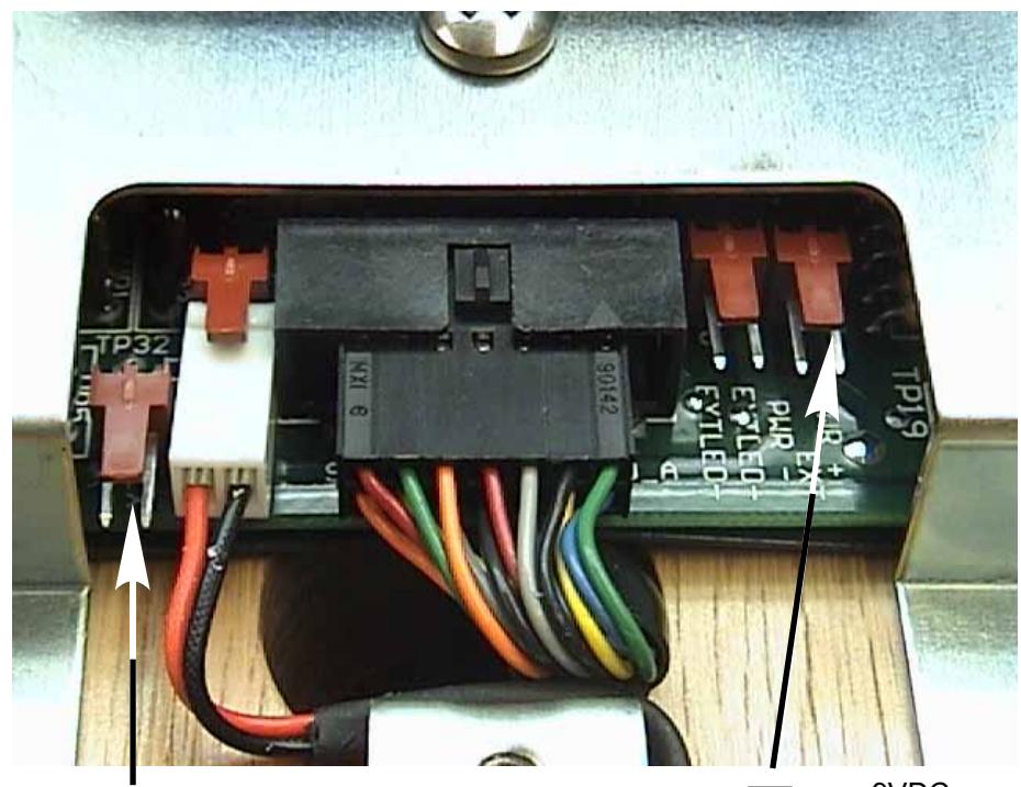
| Electrical Connections | |
| Hardwire Options Diagram | 10 |
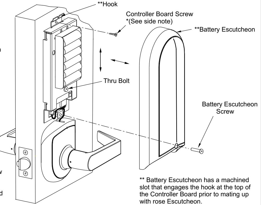
| III-C Installation Template | 11 |
IMPORTANT: The accuracy of the door preparation is critical for the proper functioning and security of this lever handle lock. Misalignment can cause premature wear and tear and a lessening of security.
SECTION I PREPARE THE DOOR
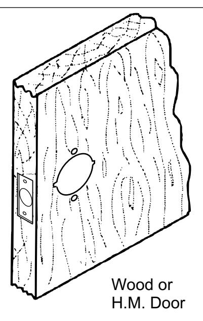
What does the door look like?
Wood Door Blank
Refer to Section IA (Below)
Tools Required
*2-1/8" (54mm) hole saw *1" (26mm) boring bit
*5/16" (8mm) drill bit *7/64" (2.5mm) drill bit *3/8" (9.5mm) drill bit
*Chisel & hammer
*#2 Phillips screw driver
*Handle removal tool (supplied)
*3/8" or 1/2"drill
Refer to Section IB (pg. 4)
I -A Prepare the Door for Lock Body & Latch
Blank Wood Door and Frame Preparation
-
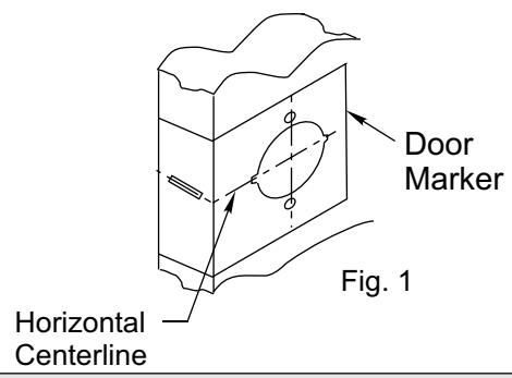
1. Mark door and position template.
- a. Draw a horizontal centerline for the lock on the edge and on both sides of the door at the desired height above the finished floor Standard height for horizontal centerline is 40-5/16" above finished floor. (See Figure1.) NOTE: If strike mortise already exist in frame, locate the horizontal centerline of the lock using strike mortise as reference.
- b. Align the door backset marker with horizontal centerline. Both sides of the door. (See Figure 1.)
- c. Draw a vertical line on center of door edge.
Caution:
Be sure to verify backset before marking & drilling door.
Note: When installing a new door in an existing frame, align centerline of lock prep with the centerline of the strike.
2. Drill door.
- a. Drill 2-1/8" (54mm) hole thru door. Cut notches as shown on template.
- b. Drill 1" (25mm) hole in edge of doorCut out for latch front 5/32" (4mm) deep 1-1/8" (29mm) wide x 2-1/4" (57mm)"high.
- c. Drill (2) 5/16" (8mm) Dia. (C) Holes through door. See Note in Fig. 2.
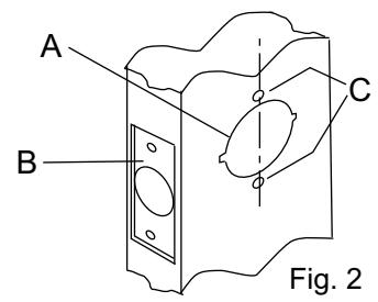
note:
To avoid splintering wood doors, drill holes from both sides.
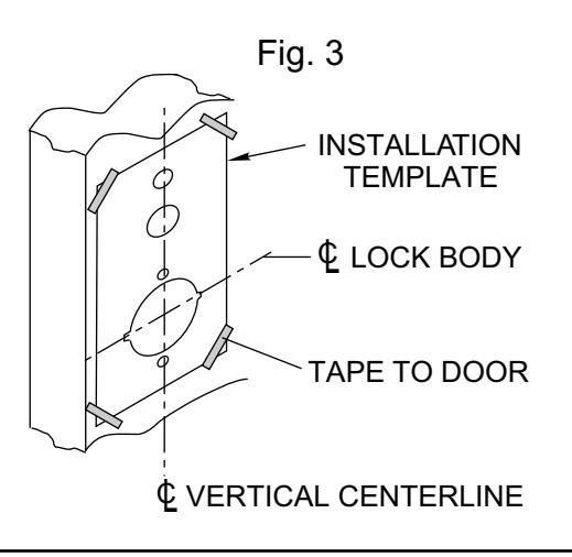
I-B. Locate and Drill Holes for Electronic Components.
-
1. Mark door and position templates (Included).
- a. Draw a horizontal centerline for the lock on both sides of the door at the desired height above the finished floor line. Standard height for horizontal centerline is 40-5/16" above finished floor (see Figure 1). (You may already have done this in Step A1a Fig.1 pg. 3.)
- b. Line up installation template with 2-1/8" cross bore and vertical backset centerline.
- c. Mark center point of additional holes to be drilled in door.
- D. Repeat step 1B for inside of door.
- 2. Drill holes in both sides of door.
SECTION II Prepare Lock for Installation
What is the hand of the door?
Face the door from the outside to determine it's hand. The outside is the keypad side of an entrance door or the corridor side of a room door.
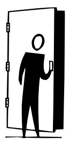
Left Hand Reverse: Hinges on left, opens outward. For handed locks, specify LHR.

Left Hand: Hinges on left, opens inward. For handed locks, specify LH.

Right Hand: Hinges on right, opens inward. For handed locks, specify RH.
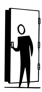
Right Hand Reverse: Hinges on right, opens outward. For handed locks, specify RHR.
If the lock body is not correct hand, See Section IIA Below.
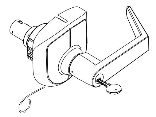
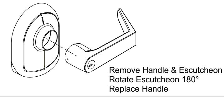
II-A How to change hands (Standard Cylinder Locks)
Remove Cylinder Handle
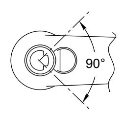
- 1. Insert key and rotate clockwise 70°.
- 2. Depress retainer with tool provided.
- 3. Slide lever off lock. (Also applies to inside lever).
RH, RHR SHOWN
LH, LHR SHOWN
Opposite Hand shown in Up-right Position.
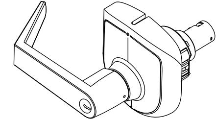
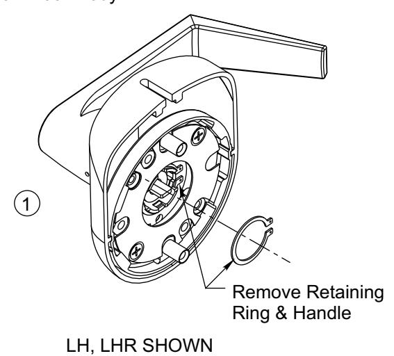
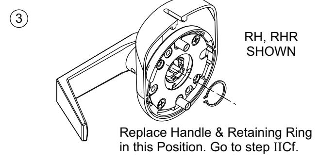
II -B How to change hands (Interchangeable Core Cylinder & Non Cylinder Locks)
Removable Core - Change Hands
Refer to steps below to remove handle assembly from Lock Body.

II -D Re-Keying
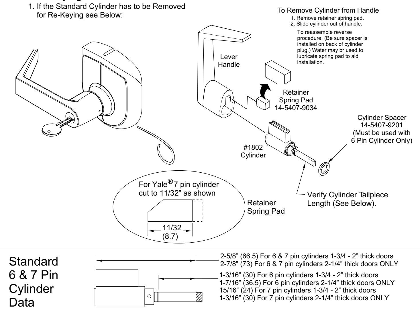
CAUTION : The cylinders furnished with the E5496LN lock for use in 1-3/4 - 2" doors have a tailpiece that is 1/4" shorter than the standard cylinders that are furnished with 5400LN locks. Trying to install a standard cylinder in 1-3/4 - 2" thick doors with a E5496LN lock will DAMAGE the lock body. Standard 6 & 7 pin cylinders may only be used on 2-1/4" thick doors provided their overall length does not exceed 2-7/8".
Competitor Cylinders
Yale Conversion Kit E107S For Schlage® Cylinders When used in 5496LN Locks
To Install Connecting Bar
- 1. Remove threaded collar and Schlage® tailpiece.
- 2. Install Connecting Bar with threaded collar. (Adjust collar for proper end play of plug.)
- 3. Slide Cylinder Cam onto Bar. (Note orientation of notch.) Fasten with roll pin.
- 4. Slide shell sleeve onto cylinder.
Follow instructions on page 3 to install cylinder into lever handle.
Schlage® Cylinder Threaded Collar Schlage® Connecting Bar 14-5496-0460-048 Schlage® Cylinder Cam 14-5407-1036-048 Roll Pin 99-9999-3942-999 (.094 Dia. x .375) Shell Sleeve 14-5407-9101-999
For Schlage® Removable Core match driver position in handle to the sketch below for proper alignment.
Correct position of Schlage® Connecting Bar when assembled toward free end of handle
Schlage® is a registered trademark of Schlage Lock Corporation

Retractor
Latch Case
3. Installing Inside Trim
SECTION III INSTALL LOCKSET (CONTINUED)

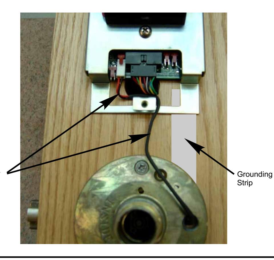
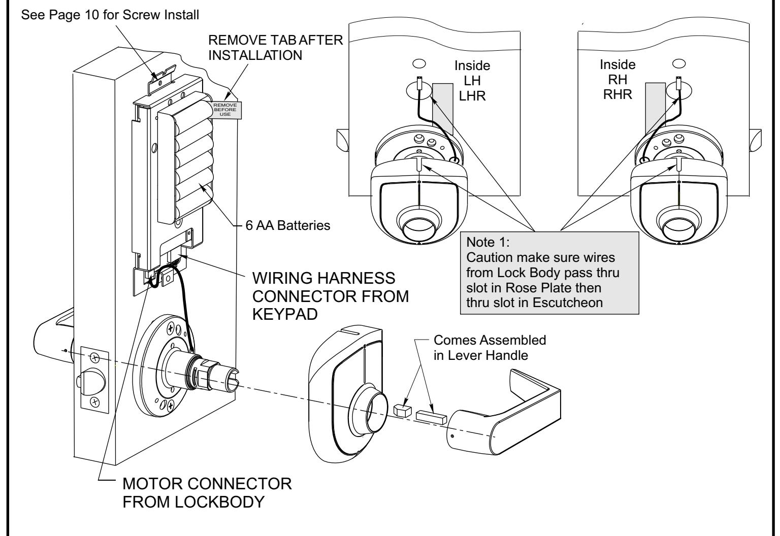
Route Lock Motor Wires above Cover Mtg. Tab
HARDWIRE OPTION DIAGRAM
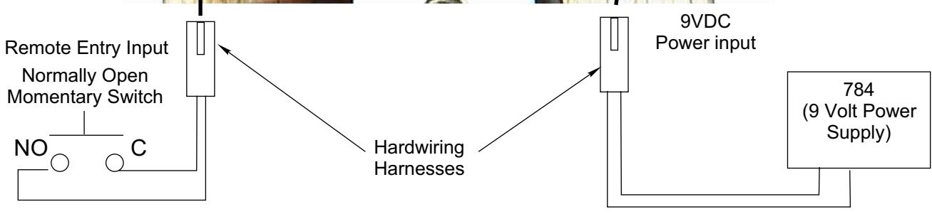
*Prior to installing the Controller Board Screw the clearance between the Battery Escutcheon and the Rose Escutcheon should be checked.
- 1. **Dry fit the Battery Escutcheon to the Rose Escutcheon.
- 2. Check the clearance where the two meet. If the clearance is acceptable remove the Battery Escutcheon and proceed to step 4.
- 3. If the clearance is to great loosen the Thru Bolt and pull down on the Controller Board (with light pressure) while tightening the Thru Bolt. Recheck clearance.
- 4. Install Controller Board Screw at the bottom of the slot (to allow additional adjustment if reqd).
- 5.** Install Battery Escutcheon and Battery Escutcheon Screw.
Yale is a registered trademark of Yale Security Inc. Other product brand names may be trademarks or registered trademarks of their respective owners and are mentioned for reference purposes only. These materials are protected under US copyright laws. All contents current at time of publication. Yale Security Inc. Reserves the right to change availability of any item in this manual, it's design, construction, and/or it's material. Copyright 2004 Yale Security Inc. all rights reserved. C
Yale
Commercial Locks & Hardware 100 Yale Avenue Lenoir City, TN 37771-3226
(865) 986-7511 (Direct) (865) 986-8630 (Fax)
Website: www.yalelocks.com