ASSA ABLOY ACCENTRA eBOSS 886F & 896F Series Exit Keypad Lock (Product Discontinued October 1, 2012_80-8420-0900
Open the original PDF document
View PDF

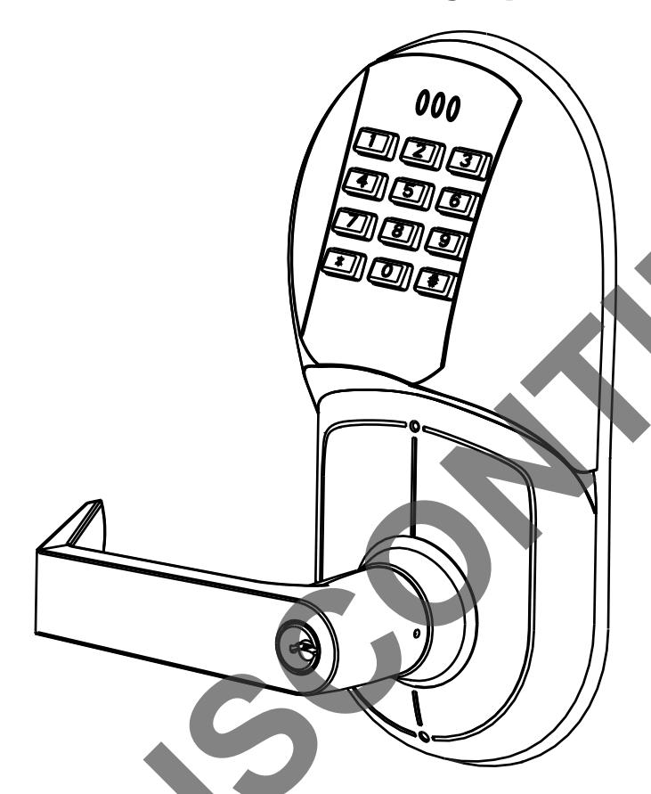
Exit Keypad Lock Installation Instructions 886F & 896F Series
2111 505 8
Electronic Battery Operated Security Solution
FEATURES
- Battery Operated (Hardwire Capable)
- Motorized Grade 1 Exit Trim
- 94 User Code Capacity
- All Metal Escutcheon and Pushbuttons
- LED Function Indicator
- Patented Free-Wheeling Levers (Patent # 4,920,773)
- Self-Adjusting for Door Thickness
- Weather Resistant
- ADA Compliant 12-Button Keypad
- Modular Design (Simple Installation)
- Audible Pushbutton
- Patented Keypad Blinders (Patent # 7,091,429)
- Request to enter input
- Emergency, Supervisor, Passage, Lockout and Master Codes
Operational Modes
Secure
Normal locked state. Any assigned user code can gain access. Lock/re-lock automatically.
Lockout
Lockset will not accept any assigned user codes except for the Supervisor and Emergency Codes.
Passage
Maintains unlocked state. Relocks by entering passage code the second time
NOTE TO INSTALLER
FAILURE TO FOLLOW THESE INSTRUCTIONS COULD RESULT IN DAMAGE TO THE LOCK AND VOID THE FACTORY WARRANTY.
Finish Care
This lockset is designed to provide the highest standard of product quality and performance. Care should be taken to insure a long-lasting finish. When cleaning is required use a soft, damp cloth. Using lacquer thinner, caustic soaps, abrasive cleaners or polishes could damage the coating and result in tarnishing.
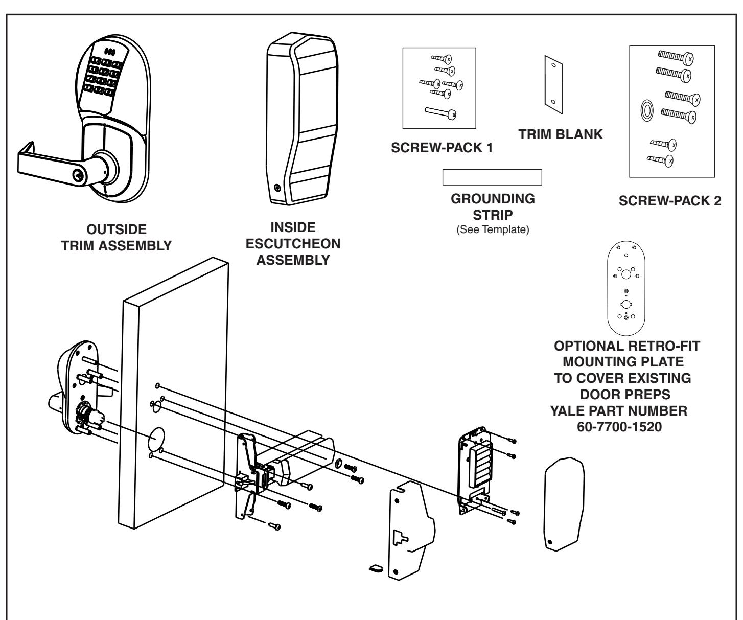
Table of Contents
| Page | |
|---|---|
| Section I Prepare the Door | 3 |
| I-A Prepare the Door | 3 |
| I-B Locate and Drill Holes for Electronic Components | 4 |
| Section II Prepare Lock for Installation | 4 |
| II-A How to Change Hands (Standard Cylinder Locks) | 4 |
| II-B How to Change Hands (Interchangeable Core Cylinder and | |
| Non Cylinder Locks) | 5 |
| II-C Re-Keying/Competitor Cylinder/ Important Cylinder Data | 6 |
| Section III The Install | 7 |
| III-A Install The Trim | 7 |
| III-B Exit Device Cover Installation | 8 |
| III-C Install Electric Components | 8 |
| Section IV Electrical Connections and Testing | 9 |
| Section V Troubleshooting | 10 _ |
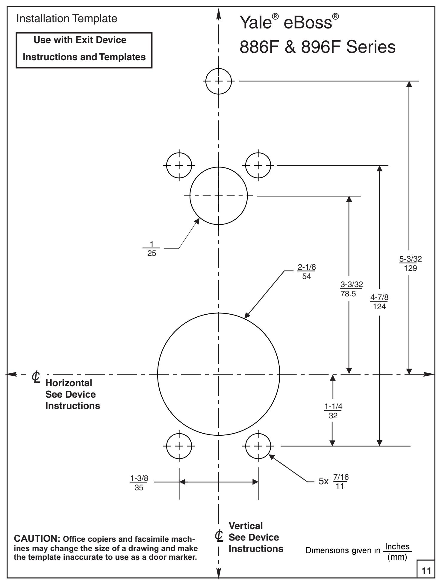
| Template | 11 |
IMPORTANT: The accuracy of the door preparation is critical for the proper functioning and security of this lever handle trim. Misalignment can cause premature wear and tear and a lessening of security. Also if the door has been previously prepped for another trim it may be necessary to use a Retro-Fit Mounting Plate to hide the excessive prep in the door. See page 2.
SECTION I PREPARE THE DOOR
What does the door look like?
Tools Required
*2-1/8" (54mm) hole saw *1" (26mm) boring bit *7/16" (8mm) drill bit
*#2 Phillips screw driver *Slotted screw driver *3/8" or 1/2" power drill
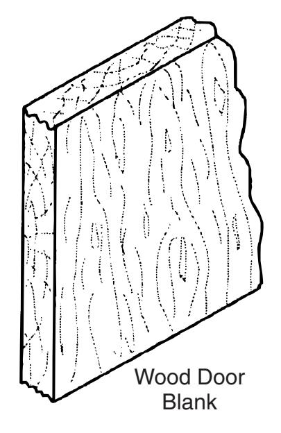
Refer to Section IA (Below)
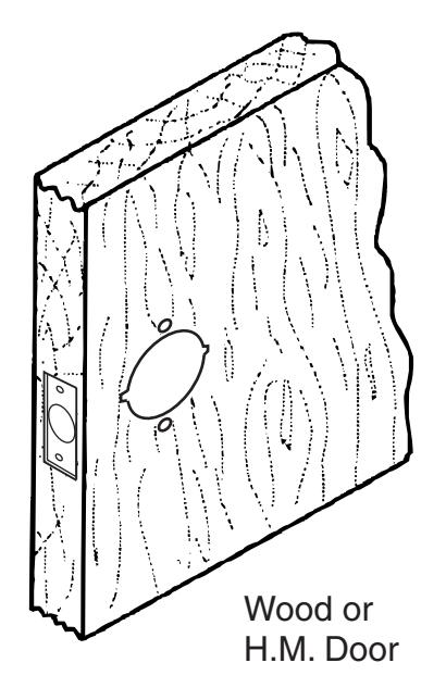
Refer to Section IB (pg. 4)
I-A Prepare the Door.
Blank Wood Door
-
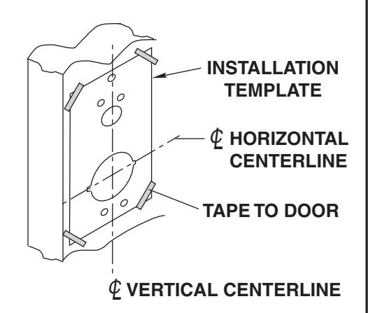
1. Mark door and position template.
- a. Refer to the Device instructions to properly draw the horizontal and vertical center lines for the lock on to the door face. This will ensure the proper backset and correct height from the finished floor.
- b. Align the door template with the vertical and horizontal center lines. Mark the location of all the holes.
- c. Repeat steps a & b on the back face of the door
Caution:
Be sure to use the door stop and not the door edge for the vertical centerline.
2. Drill door.
- a. Start with the door face and drill the 2-1/8" (54mm) hole ½ way thru the door.
- b. Drill the remainder of the holes again ½ way thru the door.
- c. Repeat steps a & b on the back face of the door.
To avoid splintering wood doors, drill holes from both sides.
3
I-B. Locate and Drill Holes for Electronic Components.
-
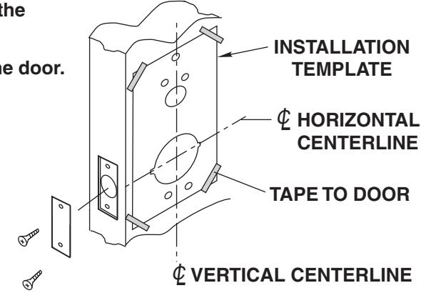
1. Mark door and position templates (Included).
- a. Align the template with the 2-1/8" (54mm) hole using the vertical and horizontal center lines.
- b. Mark the remaining hole locations on both sides of the door.
- c. Starting with the door face drill ½ way into the door
- . d Repeat drilling on the back face of the door.
- e. Use the supplied Trim Blank (60-7000-7170) and screws to cover the cylindrical latch bolt prep (if reqd).
Note: If a metal door is used, ensure it is of good quality and has the proper reinforcements installed. This will insure proper lock function.
SECTION Prepare Lock for Installation II
What is the hand of the door?
Face the door from the outside to determine its hand. The outside is the keypad side of an entrance door or the corridor side of a room door.
.
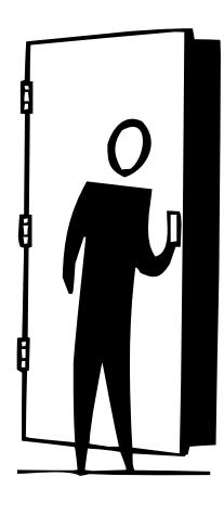
Left Hand Reverse: Hinges on left, opens outward. For handed locks, specify LHR.
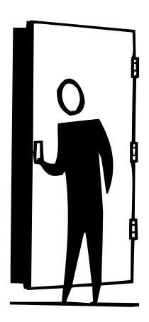
Right Hand Reverse: Hinges on right, opens outward. For handed locks, specify RHR.
If the lock body is not correct hand, See Section or on Page 5 IIA IIB
II-A How to change hands (Standard Cylinder Locks)
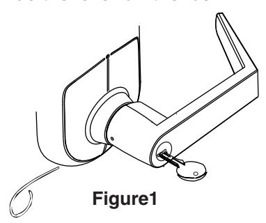
Step 1 Remove the Handle
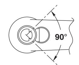
- A. Insert the key into the lock.
- B. Rotate the key 70 degrees clockwise
- C. Depress retainer with tool provided
- D. Slide the lever off the lock.
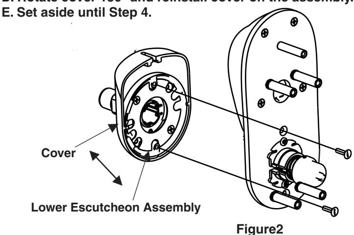
Step 3 Rotate the lockbody.
- A. Remove the small pan head screws.
- B. Rotate the lockbody 180 degrees.
- C. Reinstall the lockbody and screws.
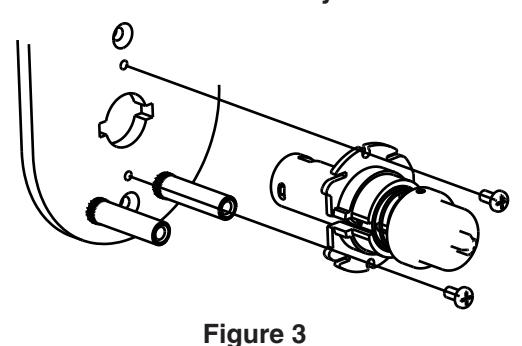
Step 2 Remove Lower Escutcheon Assembly
- A. Remove (2) slotted flat head screws.
- B. Remove lower escutcheon assembly.
- C. Remove cover from assembly by sliding it off the assembly.
- D. Rotate cover 180° and reinstall cover on the assembly.
Step 4 Reassemble
- A. With the lockbody rotated (see Step 3) and the lower escutcheon assy rotated (see Step 2) install the lower escutcheon using the (2) slotted screws.
- B. Install the handle by rotating it to the proper handing. Slide it on the shank.
- C. Install the key and rotate back to the 70 degree position (see Step 1). Continue to slide the handle until it seats completely on the shank.
- D. Rotate the key and remove the key. Insure the handle is properly installed by pulling on the handle. If the handle comes off repeat C & D.
II-B How to change hands (Interchangeable Core Cylinder & Non Cylinder Locks)
Step 1 Remove Lower Escutcheon Assembly (See step 2 above)
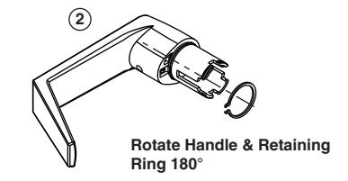
Step 2 Remove the Handle Assembly
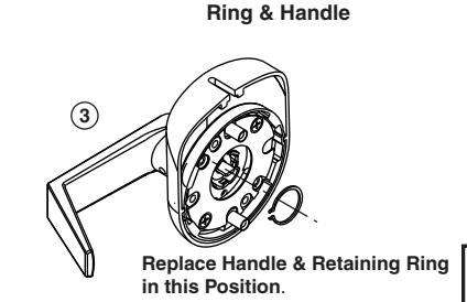
- A. Remove the retaining ring and carefully remove the handle assembly by pulling it straight out of the rose assembly.
- B. Pull the escutcheon cover off and rotate it 180 degrees and reinstall it.
- C. Rotate the handle assy 180 degrees and reinstall it by replacing the retaining ring.
Step 3 Rotate the Lockbody (See step 3 above)
Step 4 Reassemble (See step 4 above)
Remove Retaining
5

1. If the Standard Cylinder has to be Removed for Re-Keying see Below:
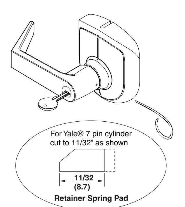
To Remove Cylinder from Handle
- 1. Remove retainer spring pad.
- 2. Slide cylinder out of handle.
Retainer Spring Pad 14-5407-9034
To reassemble reverse procedure. (Be sure spacer is installed on back of cylinder plug.) Water may br used to lubricate spring pad to aid installation.
Cylinder Spacer 14-5407-9201 (Must be used with 6 Pin Cylinder Only)
Verify Cylinder Tailpiece Length (See Below).
Standard 6 & 7 Pin Cylinder Data
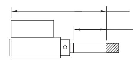
2-9/16" (65.5) For 6 pin cylinders. 2-3/8" (60.5) For 7 pin cylinders. 1-1/32" (26) For 6 pin cylinders. 7/8" (22) For 7 pin cylinders.
#1802 Cylinder
Lever
Handle
EXTREMELY * IMPORTANT!!
The cylinders furnished with the 896F are a special length. Cylinders that are not ordered with this lock will be too long. This includes 1802, E1802 and competitor cylinders. Failure to trim these cylinders will result in damage to the lock. Use the above graphic to properly size the cylinder assembly before use.
Competitor Cylinders
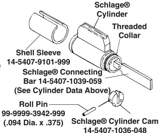
Yale® Conversion Kit E107S For Schlage® Cylinders When used in 896F Locks
To Install Connecting Bar
- 1. Remove threaded collar and Schlage® tailpiece.
- 2. Install Connecting Bar with threaded collar. (Adjust collar for proper end play of plug.)
- 3. Slide Cylinder Cam onto Bar. (Note orientation of notch.) Fasten with roll pin.
- 4. Slide shell sleeve onto cylinder.
- 5. Properly Size the cylinder (See above)
Follow instructions above to install cylinder into lever handle
For Schlage® Removable Core match driver position\nin handle to the sketch below for proper alignment.
Correct position of Schlage® Connecting Bar when assembled toward free end of handle
80-8420-0900 Rev. B (05-08)
Mechanical Install
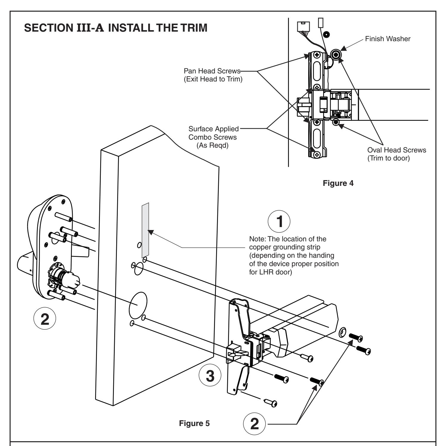
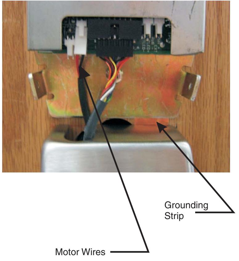
- Step1 Install the copper grounding strip on the back face of the door. The strip location is on top of one of the top 3/8" holes (depending on the hand of the device).When the device head is installed the strip connects the device head with the electronics mounting bracket.
- Step 2 Insert the trim through the holes. Route the keypad wires through the 1" diameter hole. The motor wires are routed through the 2-1/8" diameter hole. Use the oval head screws to secure the trim to the door. The bottom oval head screw does not get a washer and must be flush to below flush to clear the exit device carrier.
- 7 Step 3 Align the exit device receiving cross with the cross tip on the self-adjusting cap. Use caution not to pinch the motor wires between the exit device and the surface of the door. Use the pan head screws to secure the exit device to the trim. Do not over tighten. Double check the alignment of the device with the trim. If a misalignment is not corrected the motorized trim may not function correctly. Use the combo screws to surface apply the exit device head to the door. Continue with the device instructions and install the end cap.
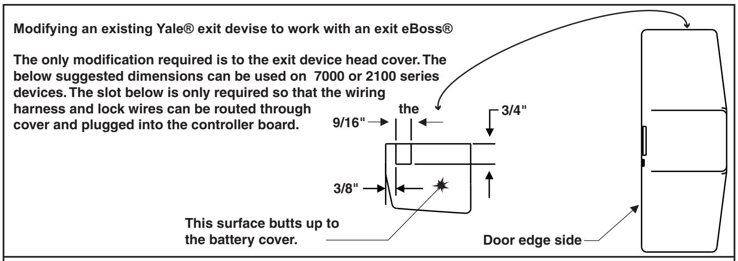
III-B. EXIT DEVICE HEAD COVER INSTALLATION
Note:
If exit eBoss® was not ordered with a 7100 or 2100 Series device the slot in the head cover may need to be added prior to cover install. Refer to page 10 for proper slot dimensions. If the device was ordered with the trim see the below steps.
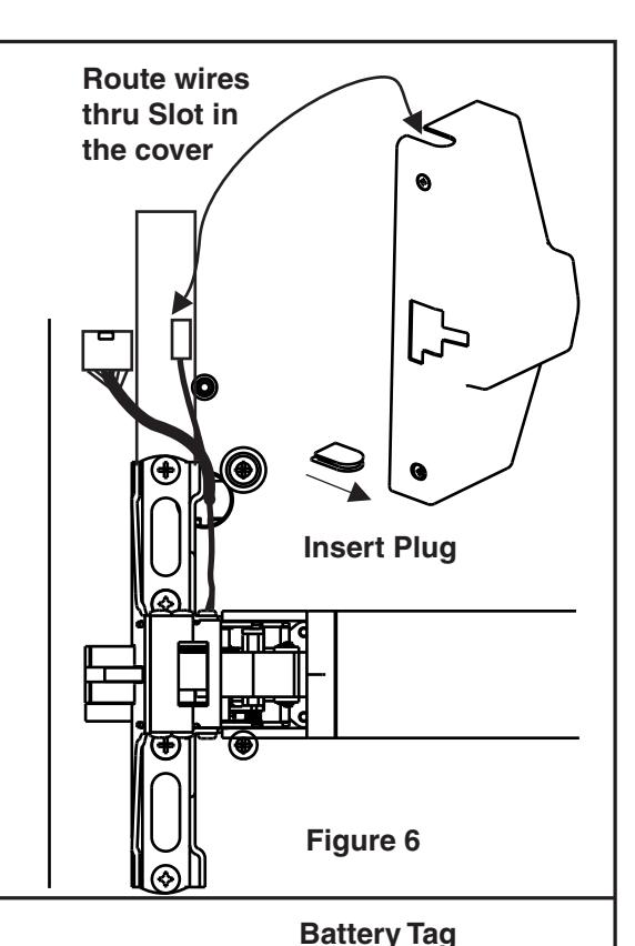
- Step 4 Install the plug in the bottom notch of the exit device cover as shown in figure 6.
- Step 5 Slide the cover onto the head while routing the wires through the top notch in the cover. Use caution so the wires are not pinched between the cover and the surface of the door.
- Step 6 Install the two cover screws.
III-C. INSTALL ELECTRONIC COMPONENTS
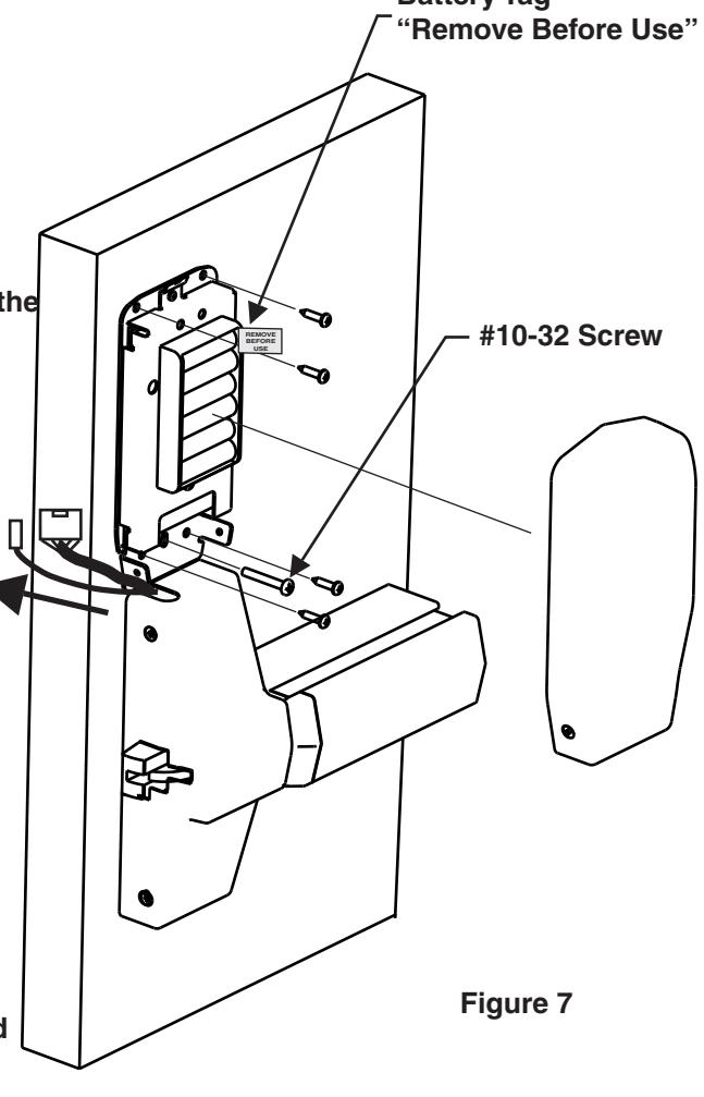
- Step 7 Slide the keypad and motor harnesses out of the way as shown (see figure 7).
- Step 8 Hold the inside electronics assembly up to the inside of the door above the device cover and install the #10-32x 1-1/2 long screw thru the slot in bracket. The screw threads into the sexbolt on the outside trim assembly. Snug the screw so that the head of the screw is centered in the slot.
- Step 9 See the picture on page 9 and connect the keypad and motor harnesses to the board as shown.
- Step 10 Dry fit the electronics cover to the electronics assembly. Reposition the electronics assembly as needed. Once the desired clearance is obtained between the electronics cover and the device head cover tighten the #10-32 screw. Set the cover aside and install the combination screws thru the bracket to provide additional strength.
- Step 11 Remove the battery tag and reinstall the battery. At this point the unit will make a beep signaling it is ready.
- Step 12 Install the electronics cover using the short #8-32 flathead screws.
- Step 13 Inspect your work. Insure everything was installed correctly.
- Step 14 Install the strike and any other components per the exit device instructions.
SECTION ELECTRICAL CONNECTIONS AND TESTING IV
At this time it is important to test the unit to insure proper installation. During step 15 do not cycle the lever or the trim.
Step 15 Type 4 3 2 1*. As you were entering the code did the numbers beep? If not refer to the troubleshooting section. After the code was entered the micro motor should have cycled inside the trim and after 10 seconds cycled again. Did this happen? If not try this step again. If after trying a second time refer to the troubleshooting section for possible solutions. If everything went well continue with step 16.
Step 16 Type 4 3 2 1 * again. After you hear the micro motor cycle rotate the lever and insure the exit device bolt retracts. After 10 seconds the micro motor will again cycle. Rotate the lever again to verify the trim re-locked (the exit device bolt does not move). If this step was not successful refer to the troubleshooting guide.
Step 17 The lock is fully installed. It is now time to program the lock. Refer to the programming guide packaged with the trim.
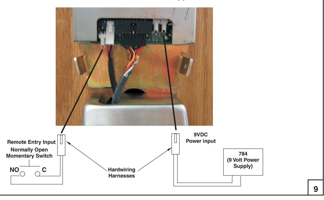
HARDWIRE AND REMOTE INPUT OPTION(s) DIAGRAM
SECTION Troubleshooting V
- 1. The Keypad does not beep or the lights do not blink when keys are pushed .
- A. Check the keypad harness to ensure it is properly connected to the electronics board.
- B. Ensure the batteries are properly installed and the "Remove Before Use" tag is removed.
- C. Are the batteries dead?
- D. Check the keypad harness for pinched or cut wires.
- E (For hard wired option) Ensure the power supply is producing 9VDC.
2. The trim does not lock or unlock.
This section is broken up into two areas. Area A is Electrical. Area B is Mechanical
A. Electrical
-
1. Can you hear the micro motor cycling in the trim? If yes refer to step B. If no follow the steps below.
- a. Check the motor harness to ensure it is properly connected to the electronics board.
- b. Is the connector installed in the proper location on the board? There is a small label on the board MTR. This is where the motor harness connects.
- c. Ensure the batteries are properly installed and the "Remove Before Use" tag is removed.
- d. Are the batteries dead?
- e. Check the motor harness for pinched or cut wires.
- f. (For hard wired option) Ensure the power supply is producing 9VDC.
B. Mechanical
- 1. Ensure the Self-Adjusting Cap is properly centered in the receiving cam of the exit device.
- 2. Was a good quality metal door with the proper reinforcements used for this install? If not the device probably is not working correctly because the door has "oil canned". This means that when the through bolts were tightened it caused the door to crush like an hour glass causing severe misalignment between the trim and the exit device. This problem may be corrected by loosening the pan head screws shown in figure 4. First try ½ turn (loosen) on each of the pan heads. Try the lock again. If this does not fix the problem try another ½ turn. If this solves the problem, ensure the surface applied screws provided are installed and tight.
- 3. Another misalignment can be caused by a bad door prep. Ensure the door is properly prepped with the template contained with these instructions and the template supplied with the exit device.
- 4. Finally, a third type of misalignment may be present. This is where the exit device has sagged on the door causing the exit device to hang on the lockbody inside the trim causing internal misalignment. Loosen the exit device screws and slightly lift the device while tightening the screws again.
If the above tips do not solve your problem please call our Technical Product Support Team at the phone number listed on the back of these instructions.
10
| 100 Yale Avenue, Lenoir City, TN 37771 • Product Support Tel 800.438.1951 • Fax 800.338.0965 • www.yalecommercial.com | |
|---|---|
|
Yale® and
eBoss® are registered trademarks of Yale Security Inc. Other products' brand names may be trademarks or registered trademarks of their respective |
|
| owners and are mentioned for reference purposes only. These materials are protected under U.S. copyright laws. All contents current at time of publication.Yale Security Inc. reserves | |
| the right to change availability of any item in this catalog, its design, construction, and/or its materials. Copyright © 2008,Yale Security Inc. | |
| All rights reserved. Reproduction in whole or in part without the express written permission of Yale Security Inc. is prohibited. | |
| 12 | |