ASSA ABLOY ACCENTRA eBOSS 8850FL Series Mortise (Product Discontinued October 1, 2012) Installation_80-9086-0050-010
Open the original PDF document
View PDF

E ... b o s s °
8850FL Series Mortise Installation Instructions
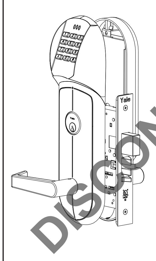
FEATURES
- Battery Operated (Hardwire Capable)
- Motorized Grade 1 Mortise Lock
- 94 User Code Capacity
- All Metal Escutcheon and Pushbuttons
- LED Function Indicator
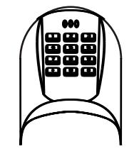
- Weather Resistant, ADA Compliant 12-Button Keypad
- Modular Design (Simple Installation)
- Audible Pushbutton
- Patented (Pat # 7,091,429) Keypad Blinders
- Request to Enter Input
- Emergency, Supervisor, Passage, Lockout and Master Codes
- Deadbolt Monitoring Feature for Deadbolt Applications (8852FL & 8853FL).
Operational Modes
Secure
Normal locked state. Any assigned user code can gain access. Lock relocks automatically.
Lockout
Lockset will not accept any assigned user codes except for the Supervisor and Emergency Codes.
<u>Passage</u>
Maintains unlocked state. Relocks by entering passage code the second time.

Table of Contents
| Section I List of components | |||
|---|---|---|---|
|
A. Necessary Tools2
B. Non-Deadbolt functions 8850FL-8851FL3 C. Deadbolt functions 8852FL-8853FL4 |
|||
| Section II Prepare the door | |||
|
A. Determine hand of door5
B. Mark centerline for lever position and door template5 C. Drill holes in door5 D. Mark frame for strike mortise cavity5 E. Drill mortise cavities in door and frame5 F. Install strike5,6 |
|||
| Section III Handing the Mortise Lock | |||
|
A. Handing the latchbolt6
B. Handing the hubs6 |
|||
| Section IV Installing Assembly on Door | |||
|
8850FL & 8852FL
A. Installing keypad, long escutcheon and controller board 7 B. Installing lockbody, short escutcheon and levers8 |
|||
|
8851FL & 8853FL
C. Installing keypad and controller board9 D. Installing lockbody, large escutcheon, small escutcheon and levers10 |
|||
|
8850FL, 8851FL, 8852FL, 8853FL
E. Installing the battery escutcheon and adjusting for appearance11 F. Tightening the cylinder (if needed) and installing the armor front12 G. Template for drilling a mortise pocket on the edge of a door 13 |
|||
| Section V Hardwire Options Diagram | |||
| A. Hardwire options diagram12 | |||
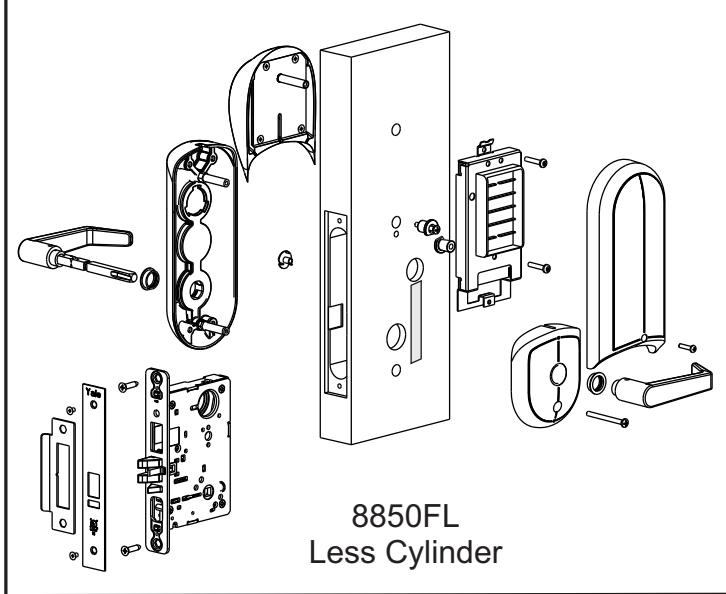
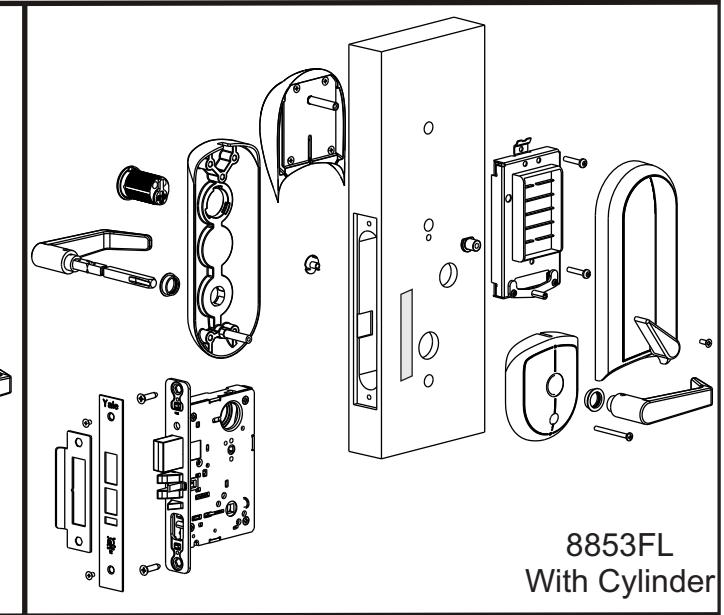
Section I List of Components
I-A Necessary tools
#2 Phillips screwdriver #3 Phillips screwdriver 1/8" Allen wrench Small flat blade screw driver Hole saw set

or
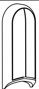
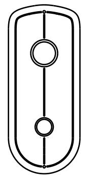
O/S Long Escutcheon W/O Cylinder
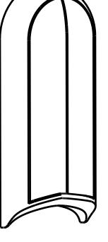
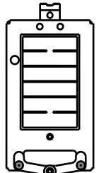
Battery Escutcheon

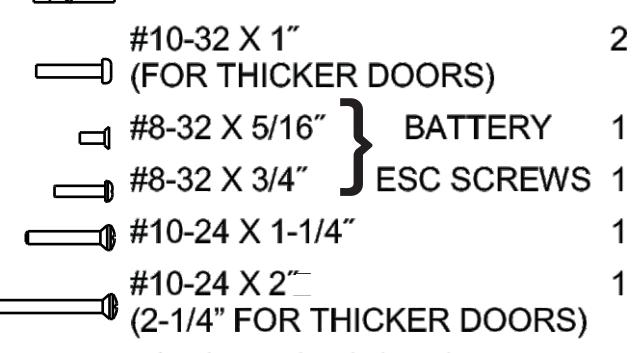
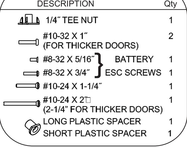
DESCRIPTION Qty
SCREW PACK
O/S Long Escutcheon W/ Cylinder
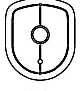
I/S Short Escutcheon
Keypad Assembly
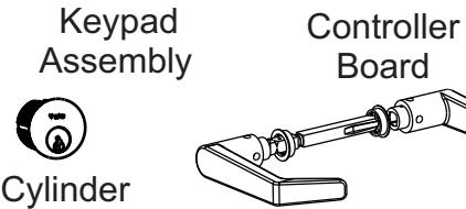
Spindle Asm
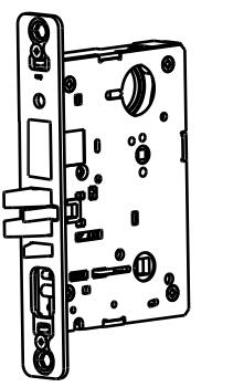
Mortise Lockbody

Grounding Strip
| Cylinder Chart | |
| Door | Cylinder |
| Thickness | Size |
|
1-3/4
˝ |
1-3/4
˝ |
|
2
˝ |
1-3/4
˝ |
|
2-1/4
˝ |
2
˝ |
| STRIKE PACK | ||
|---|---|---|
| DESCRIPTION | Qty | |
| STRIKE | 1 | |
|
ARMOR
FRONT |
1 | |
|
COMBINATION 4
SCREW |
||
|
ARMOR
FRONT SCREW |
2 | |

or
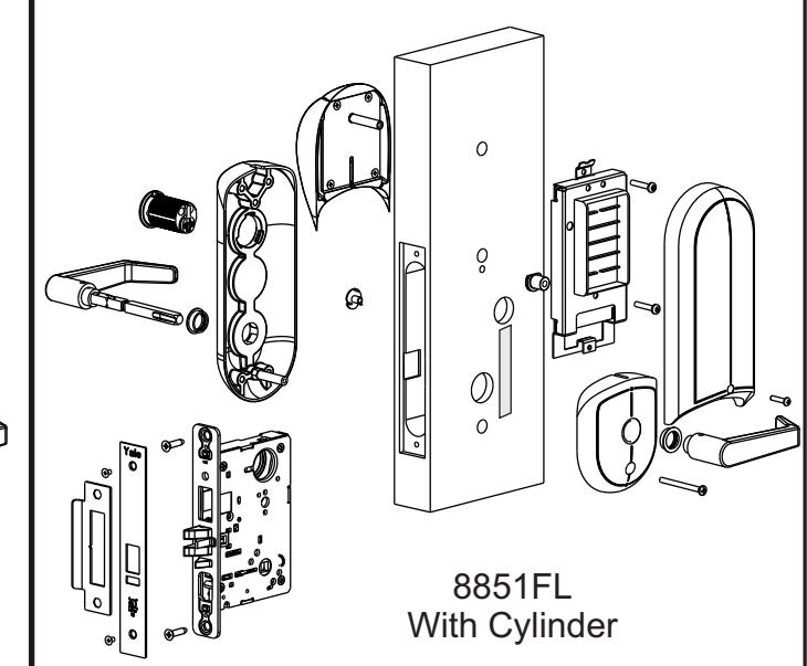
O/S Long Escutcheon W/ Cylinder
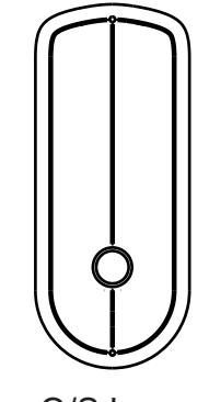
O/S Long Escutcheon W/O Cylinder
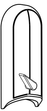

Escutcheon
SCREW PACK

I/S Short Escutcheon
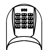
Keypad Assembly
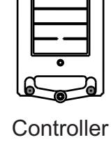
Board
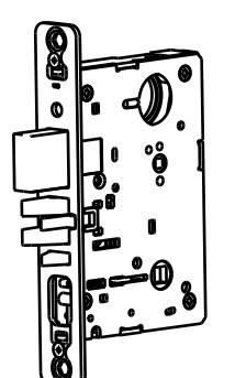
Mortise Lockbody

Grounding Strip

Spindle Asm
| Cylinder Chart | ||
|---|---|---|
| Door | Cylinder | |
| Thickness | Size | |
| 1-3/4 | 1-3/4 | |
| ˝ | ˝ | |
| 2 | 1-3/4 | |
| ˝ | ˝ | |
| 2-1/4 | 2 | |
| ˝ | ˝ | |
| STRIKE PACK | |
|---|---|
| DESCRIPTION | Qty | |
|---|---|---|
| STRIKE | 1 | |
|
ARMOR
FRONT |
1 | |
|
COMBINATION
SCREW |
4 | |
|
ARMOR
FRONT SCREW |
2 |
Section II Prepare the Door
A) Determine hand of door
Face the door a from the outside to determine its hand. Please note the outside is either the key side of an entrance door or the corridor side of a room door. The outside of a single communication door is the side opposing the hinges. The outside of a twin communicating doors is the space between the doors.


- B) Mark centerline for lever position and door template
- 1. Draw a horizontal centerline for the lock lever/spindle on both sides of door at desired height above finished floor line. Standard height for horizontal centerline is 39-15/16˝ above finished floor.
- 2. Compare the lock function number being installed with hole chart (See Template) to determine the holes to be marked.
- 3. Position the installation template on the door so that the horizontal centerline lines up with the marked horizontal line on the door, and the desired edge of the template lines up with the edge of the door.
- 4. Mark the holes to be drilled using a scribe, center punch, or nail on the inside and outside of door. To avoid shifting of the template, it may be taped to the door during this step.
- C) Drill holes in door
- 1. Bore marked trim holes (step B4). To avoid splintering wood, bore thru holes from both sides of door.
- D) Mark frame for strike mortise cavities
- 1. Mark the vertical position of strike on jamb using the reference centerline on installation template. Mark location of strike lip.(FIRST DETERMINE IF SILENCERS ARE TO BE USED) To locate horizontal centerline of strike, take half the door thickness PLUS the thickness of silencer (if used). Use this dimension to locate the strike centerline from the doorstop. (See Fig. 1, page 6)
- E) Drill Mortise Cavities in door and frame
- 1. Align mortise pocket template on edge of door using the spindle height mark.
- 2. Mark door edge for lock body attaching screws and mortise pocket.
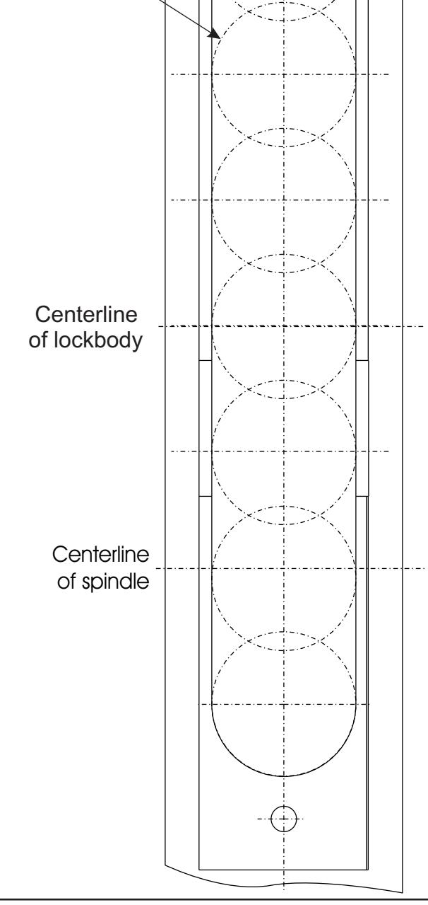
- 3. Mortise door edge for lock body 4½˝ deep. See page 14 for Template.
- 4. Drill pilot holes for attaching screws.
- 5. Slide lock body into cavity and attach using the combination attaching screw. Install armor front and use as template. Mark outline.
- 6. Mortise door edge for lock front (7/32˝) deep.
- 7. Mortise jamb for strike (3/32˝ deep). Be sure to mortise 1˝ (25mm) deep to accommodate lock bolts or strike
- F) Install Strike
- 1. Attach strike to jamb using two #12 combination attaching screws. (See Fig. 1, page 6).
Section II Prepare the Door (CONTINUED)
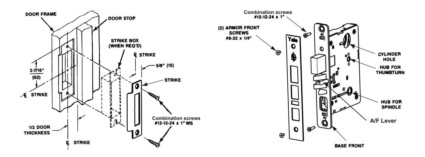
(Fig.1) 8800 Series Strike Shown (Fig.2) 8800 Series Lock Shown
Section III Handing the Mortise Lock
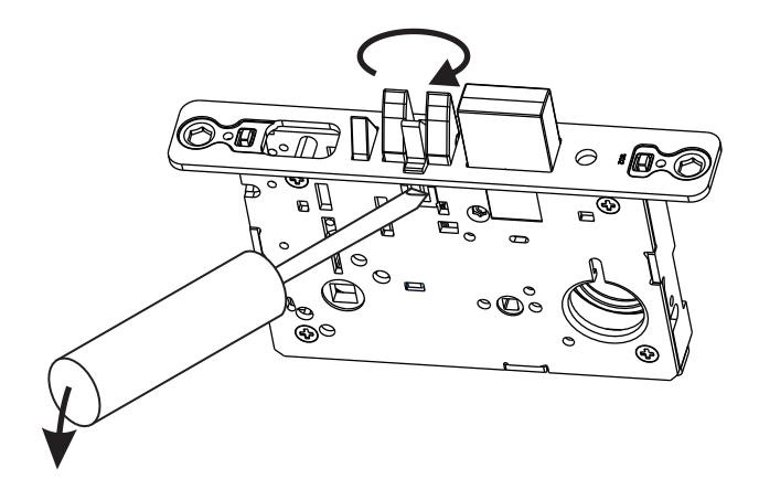
Handing the Latchbolt
- 1. Insert flat blade screwdriver into cover slot.
- 2. Pull back on screwdriver until latchbolt extends past base front and rotate the head to the desired position.
Handing the Hubs
- 1. Locate RED MARK on locking piece.
- 2. Push toggle button slide away from "square spindle hole".
- 3. With blade screw driver push RED MARK on slide nearest "square spindle hole".
- 4. RED MARK indicates locked side!
Section IV Installing Assembly on Door
IV-A Installing keypad, long escutcheon and controller board
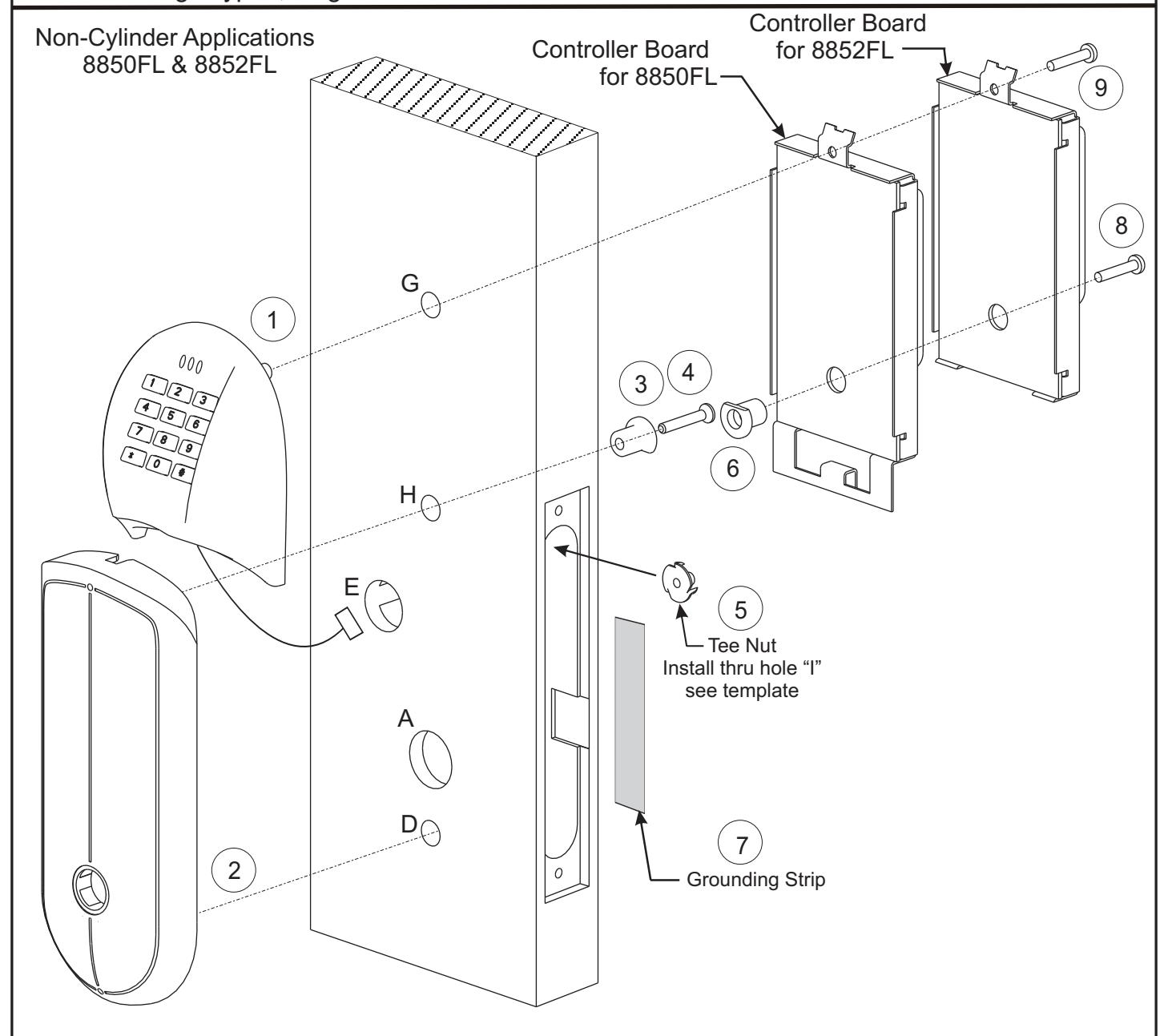
Steps
- 1. Install keypad housing:
- a) Route keypad harness thru hole "E", all the way thru door.
- b) Route keypad post thru hole "G".
- 2. Install O/S long escutcheon posts in holes "D" and "H". This will hole the keypad in place.
- 3. Install short plastic spacer with flat down in hole "H" on inside of door.
- 4. Securely fasten the #10-24 X 1-1/4 screw thru the short plastic spacer. "
- 5. Install the tee nut from the inside of the mortise pocket thru hole "I". See template.
- 6. Install long plastic spacer with flat up in the back of the controller board.
- 7. Secure grounding strip to door making sure the strip connects the controller board to the I/S Short Esc.
- 8. Loosely fasten the controller board to the tee nut using #10-32 X 1 screw thru the long plastic spacer. "
- 9. Loosely fasten the top of the controller board using #10-32 X 1 screw thru hole "G". "
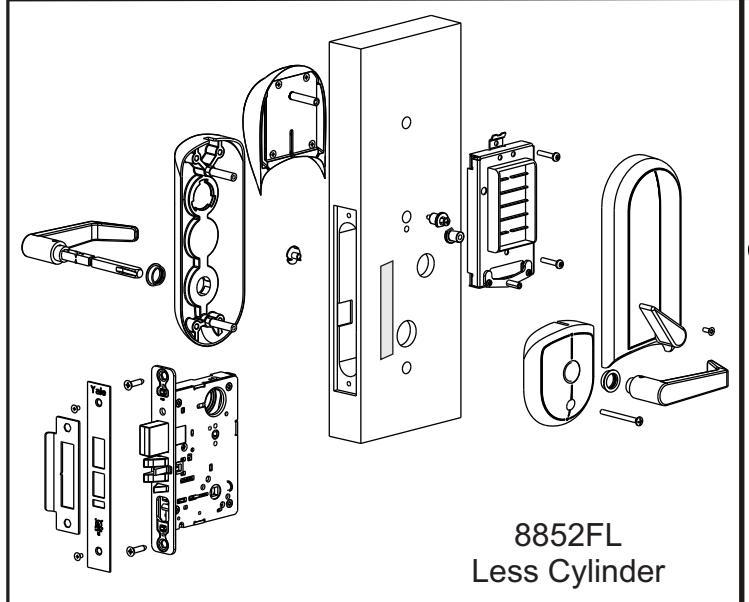
Non-Cylinder Applications 8850FL & 8852FL
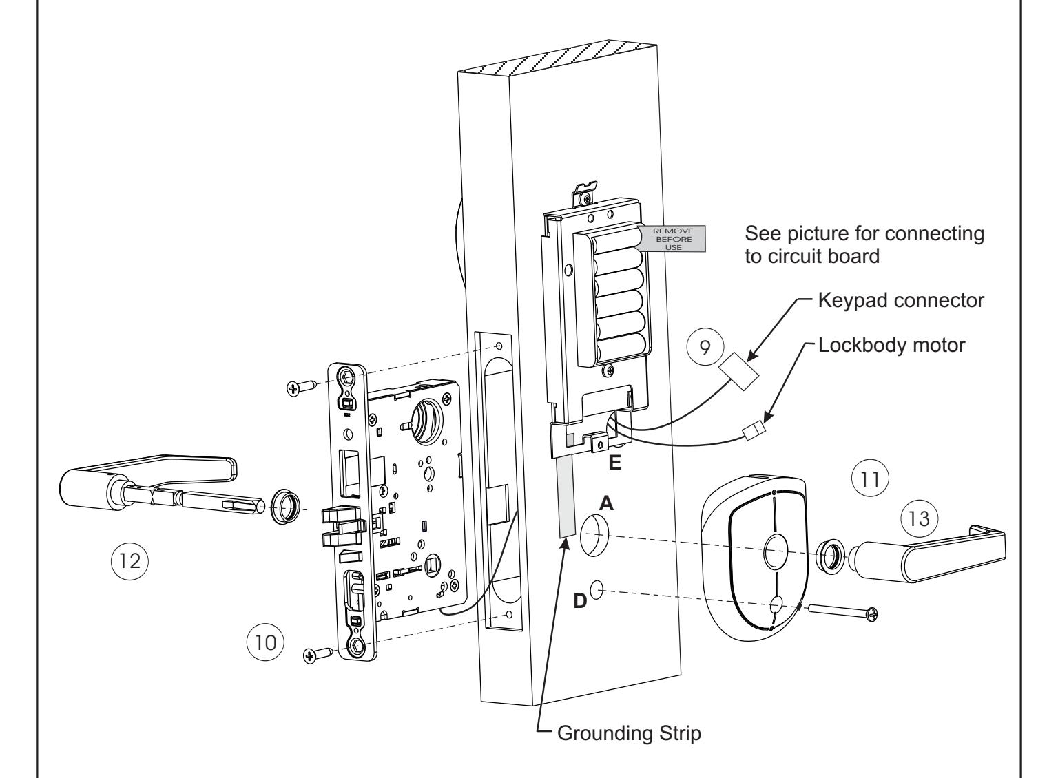
Steps
- 9. Route all lockbody harnesses thru the mortise pocket and thru hole "E".
- 10. Loosely fasten lockbody to door using combination screws.
- 11. Install I/S short escutcheon by loosely attaching the #10-24 X 2" screw thru hole "D" and to the post of the O/S long escutcheon.
- 12. Installing the spindle assembly thru the lock. Loosen the set screw on the inside lever and remove inside lever before installing thru lock. Be sure that the lever on the pinned end of the assembly goes on the outside of the door and the ramp of the inside spindle goes towards the set screw on the inside lever.
- 13. Install the inside lever and securely tighten the set screw.
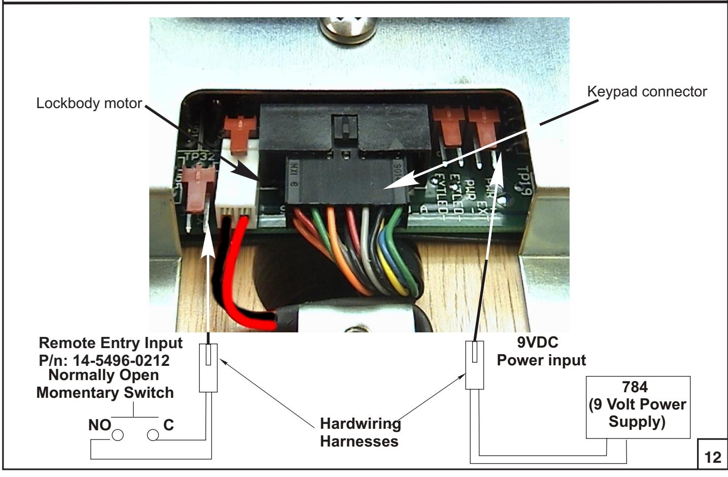
- 14. Install harness connectors to the controller board (see Wiring Diagram on page 12).
- 15. Skip to page 11.
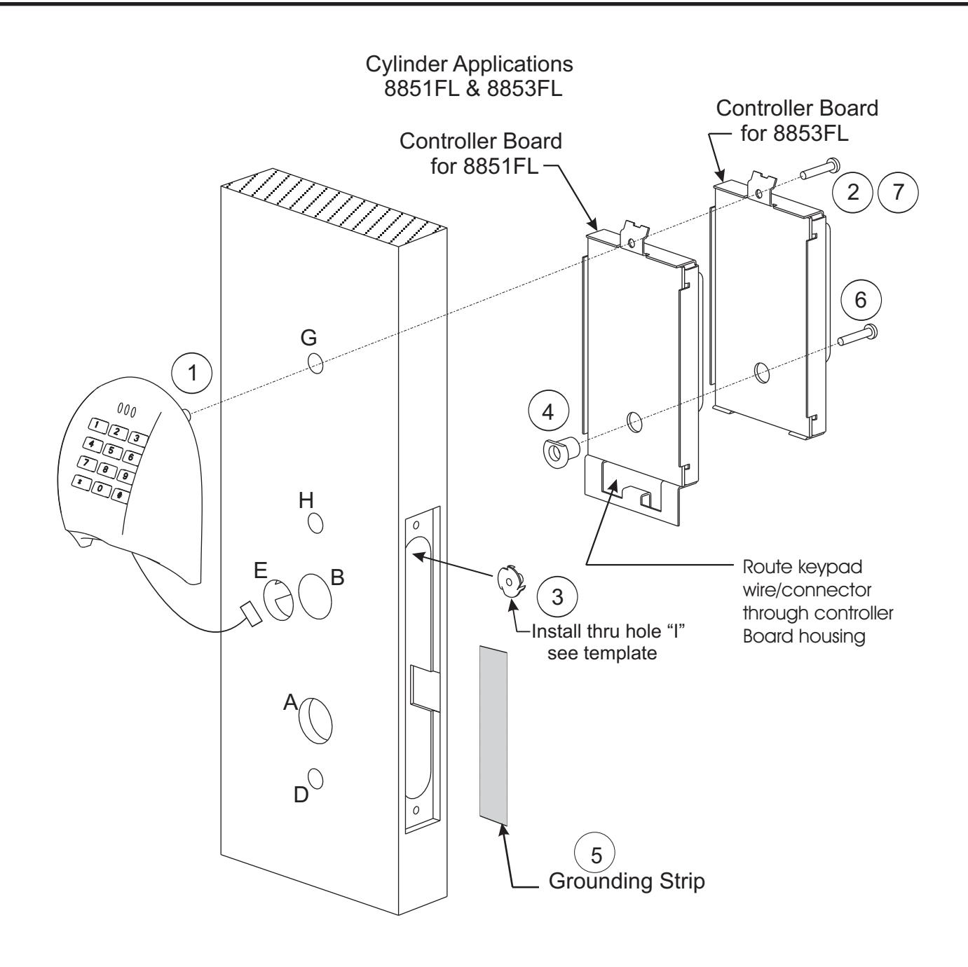
Steps
- 1. Install keypad housing:
- a) Route keypad harness thru hole "E", all the way thru door
- b) Route keypad post thru hole "G".
- 2. Loosely fasten the #10-32 X 1 screw thru hole "G" and into the keypad post. "
- 3. Install the tee nut from the inside of the mortise pocket thru hole "I". See template.
- 4. Install the long plastic spacer (with flat any orientation) in the back of the controller board.
- 5. Secure grounding strip to door making sure the strip connects the controller board to the I/S Short Esc.
- 6. Loosely fasten the controller board to the tee nut using #10-32 X 1 screw thru the long plastic spacer. "
- 7. Loosely fasten the #10-32 X 1 screw thru hole "G" and into the keypad post. "
Cylinder Applications 8851FL & 8853FL
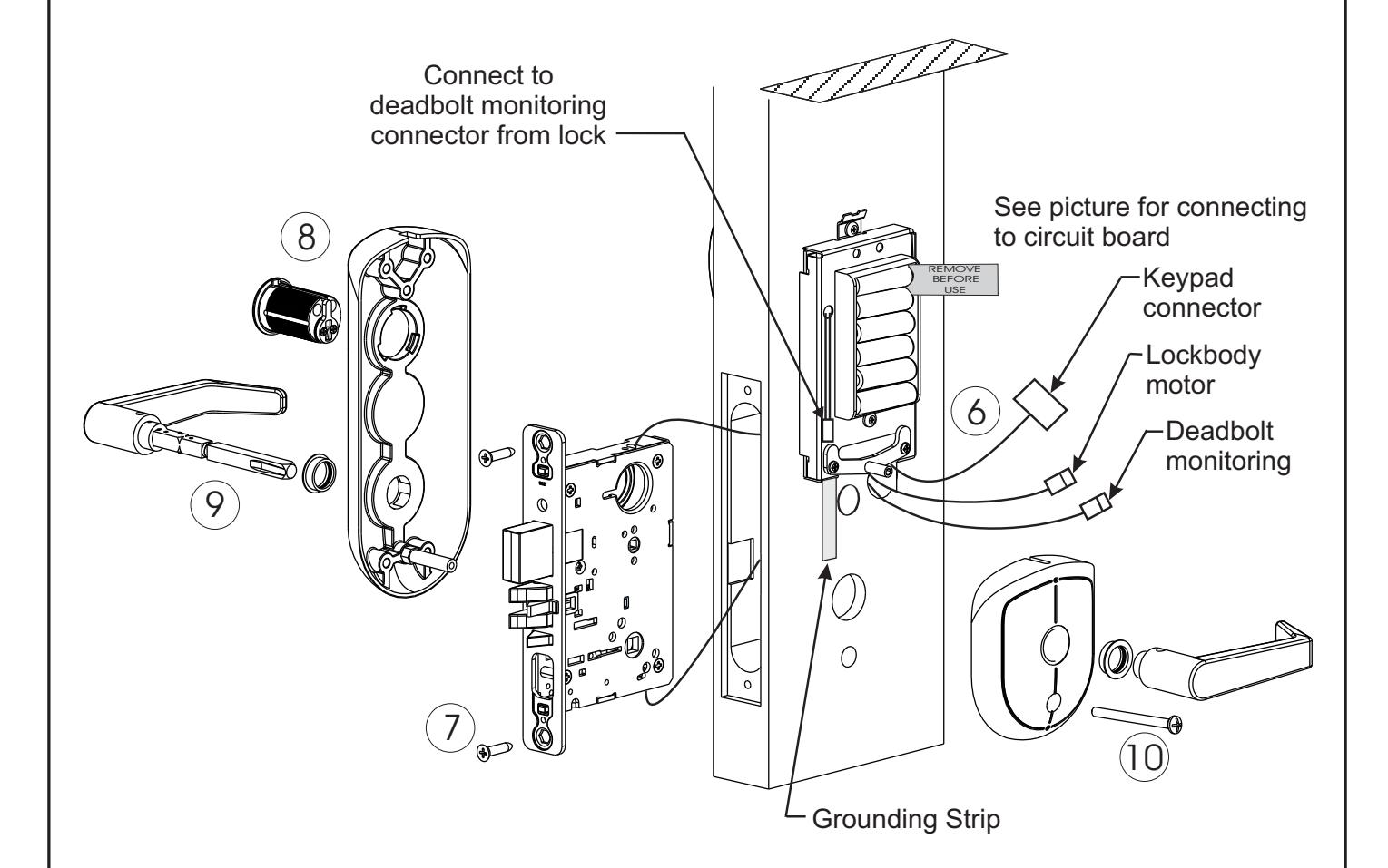
Steps
- 6. Route all lockbody harnesses thru the mortise pocket and thru hole "E".
- 7. Loosely fasten lockbody to door using combination screws.
- 8. Install the bottom post of O/S long escutcheon thru hole "D" and attach the cylinder to the lockbody thru hole "B".
- 9. Install the I/S short escutcheon by loosely fastening the #10-24 X 2" screws thru hole "D" and to the post of the O/S long escutcheon.
- 10. Install the spindle assembly thru the lock. Loosen the set screw on the inside lever and remove inside lever before installing thru lock. Be sure that the lever on the pinned end of the assembly goes on the outside of the door and the ramp of the inside spindle goes towards the set screw on the inside lever.
- 11. Install the inside lever and securely tighten the set screw.
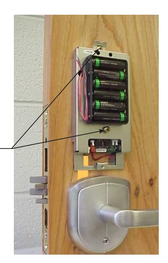
- 12. Install harness connectors to the controller board (See Wiring Diagram on page 12). For deadbolt monitoring connection see picture above.
- 13. Skip to page 11.
IV-E Installing the battery escutcheon and adjusting for appearance
All Applications
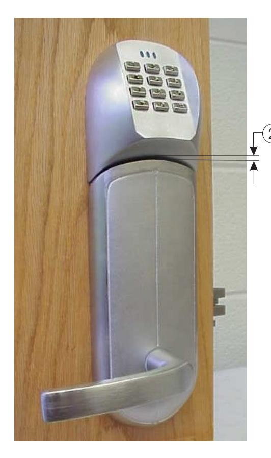
2 Minimize gap between keypad and escutcheon by gently pushing them together, then tighten both controller board screws.
Installing the Battery Escutcheon and minimizing the clearance between the Battery Escutcheon and the Small Rose Escutcheon.
- 1. **Dry fit the Battery Escutcheon to the Small Rose Escutcheon.
- NOTE: IT IS VERY IMPORTANT TO KEEP WIRES FROM GETTING PINCHED WHILE ATTACHING BATTERY COVER.
- 2. Check the clearance where the two meet, see top picture. If the clearance is acceptable tighten the Battery Escutcheon screw.
- 3. If the clearance is too great loosen the Small Rose Escutcheon screw then push up and re-tighten the screw. Recheck clearance. If the clearance is still not acceptable remove Battery Escutcheon and loosen the two Controller Board screws and adjust the controller board up or down. Re-tighten controller board screws and refer to step #2.
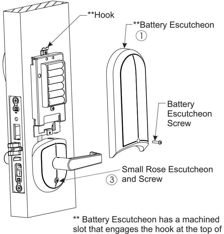
the Controller Board prior to mating up
with Rose Escutcheon.
IV-F Tightening the cylinder (if needed) and installing the armor front
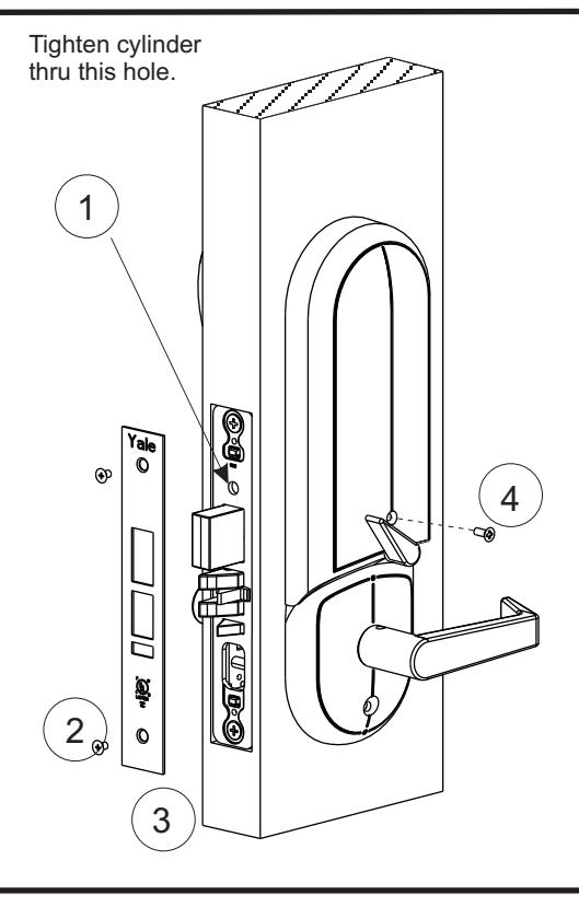
- 1. Align the cylinder face to desired orientation and tighted the cylinder thru the hole indicatied above.
- 2. Securely fasten the lockbody screws.
- 3. Install the armor front with the 2 #10 x 21 5/16" screws provided.
- 4. Fasten battery cover screw.
Section V WIRING DIAGRAM
V-A Wiring diagram
IV-G Template for drilling a mortise pocket on the edge of the door
1 3/4" 1 1/4" Ø 1-1/16 X 4.5˝ DEEP
Finish Care
This lockset is designed to provide the highest standard of product quality and performance. Care should be taken to insure a long-lasting finish. When cleaning is required use a soft, damp cloth. Using lacquer thinner, caustic soaps, abrasive cleaners or polishes could damage the coating and result in tarnishing.
If installation instructions are not followed this may result in damage to the lock and void the factory warranty. Removing cover screws voids lock body warranty. Any retrofit or other field modification to a fire rated opening can potentially impact the fire rating of the opening, and Yale Locks & Hardware makes no representations or warranties concerning what such impact may be in any specific situation. When retrofitting any portion of an existing fire rated opening, or specifying and installing a new fire-rated opening, please consult with a code specialist or local code official (Authority Having Jurisdiction) to ensure compliance with all applicable codes and ratings.
Product Support Tel 800.810.WIRE (9473) • www.yalelocks.com
Yale Locks & Hardware is a division of Yale Security Inc., an ASSA ABLOY Group company.
Yale® and eBoss® are registered trademarks of Yale Security Inc., an ASSA ABLOY Group company. Other products' brand names may be trademarks or registered trademarks of their respective owners and are mentioned for reference purposes only. These materials are protected under U.S. copyright laws. All contents current at time of publication. Yale Security Inc. reserves the right to change availability of any item in this catalog, its design, construction, and/or its materials.
Copyright © 2005, 2012 Yale Security Inc., an ASSA ABLOY Group company. All rights reserved. Reproduction in whole or in part without the express written permission of Yale Security Inc. is prohibited.