ASSA ABLOY ACCENTRA UNI-TJ50BC Series, Unitrol Top Jamb Arm, Non-Hold Open & Hold Open_80-9350-2517-010
Open the original PDF document
View PDFYale
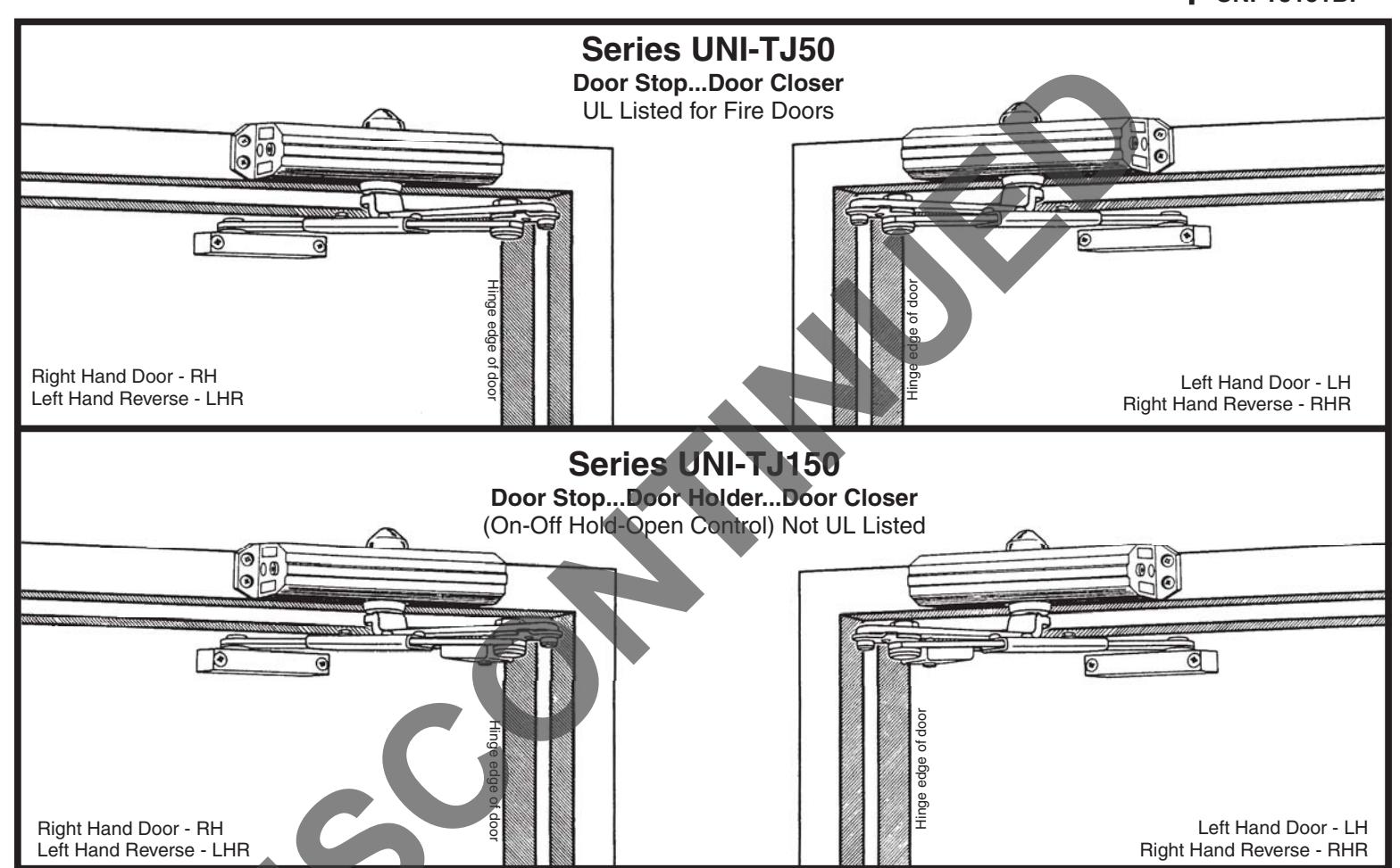
UNI Stop/Holder UNI-TJ50BC Series Sized Closers UNI-TJ51(BF) Series Multi-Sized Closers
Installation Instructions
80-9350-2517-010 (06-09) Non Handed Door Closers
AN INCORRECTLY INSTALLED OR IMPROPERLY OF ADJUSTED DOOR CLOSER CAN CAUSE PROPERTY DAMAGE OR PERSONAL INJURY. THESE INSTALLATION INSTRUCTIONS SHOULD THE FOLLOWED TO AVOID THE POSSIBILITY OF MISAPPLICATION OR MISADJUSTMENT.
Non Hold Open & Hold Open (TJ150) Models
Sized (Sizes 2,3,4,5,6) UNI-TJ52BC UNI-TJ152BC UNI-TJ53BC UNI-TJ153BC UNI-TJ54BC UNI-TJ154BC UNI-TJ55BC UNI-TJ155BC
UNI-TJ56BC UNI-TJ156BC
Multi-Sized (Sizes 3 thru 6) UNI-TJ51 UNI-TJ151
(Sizes 1 thru 4) UNI-TJ51BF UNI-TJ151BF
- NOTE: For special applications a separate door and frame preparation template is packed with these instruction. Use this instruction sheet for installation sequence and closer adjustments only.
- It is recommended that the door, on which the door closer will be installed, be hung on ball bearing hinges. Door must swing freely.
- Door and Frame must be properly reinforced, or use of special fasteners employed, to prevent the mounting screws from pulling
- All dimensions are given in inches with corresponding metric dimensions (millimeters) in parenthesis.
Hollow-Metal or Wood Openings
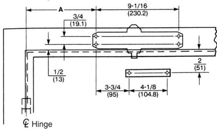
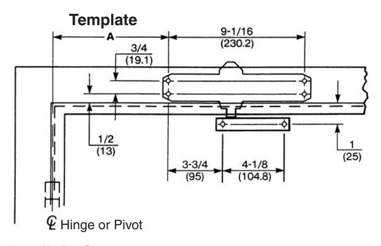
Template
Installation Sequence
- This page for installation on hollow-metal or wood. For aluminum doors and frame use page 3.
- Select door opening angle using template above. Mark 4 holes on frame face for closer and 2 holes on door for arm foot.
- Prepare door and frame for fasteners. See "Preparation for Fasteners" below.
- 51 and 51BF Models Only. Set closing power using "Power Adjustment Chart" at bottom of page 3.
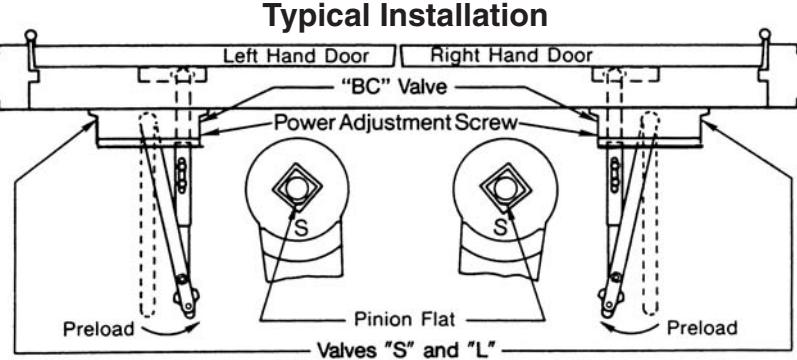
- Install closer to frame face with 2 regulating valves toward hinge edge of door.
- Remove rod unit from arm assembly.
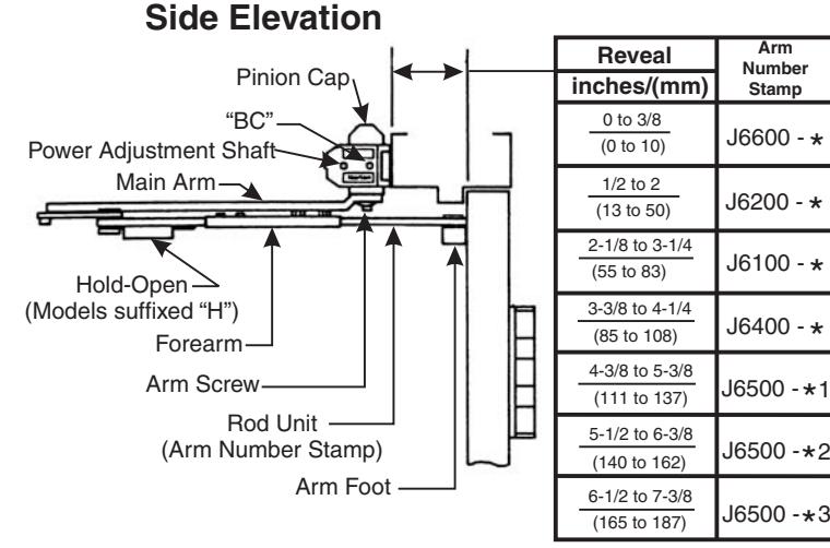
- Install main arm onto closer pinion shaft, indexing main arm mark "S" with Pinion flat as shown at right. Fasten with arm screw.
- Mount arm foot to door. Position foot with rod on top.
- Reassemble arm. Adjust forearm perpendicular (at a 90° angle) to door. Tighten rod screws.
- Snap pinion cap in place.
| Adjust closer. | |||||||
|---|---|---|---|---|---|---|---|
| Preparation for Fasteners | |||||||
| Frame Door | Fasteners | Drill | |||||
| metal | Does not |
1/4"-20
machine screw |
#7 (.201" dia.) or 5.10mm. drill
1/4-20 tap |
||||
| wood | apply |
#14 type "A" sheet
metal screw |
3/16" (4.30mm.) | ||||
| Does not apply |
Hollow-
metal |
SNB |
9/32" (7.00mm.) thru
3/8" (9.50mm.) door face opposite to closer |
||||
|
aluminum
or wood |
3/8" (9.50mm.) thu | ||||||
Opening Dimension "A" Hold-Open inches Stop mm. 85° 90° 9-1/8 232 8-3/8 213 100° 7-3/4 197 100° 7-3/8 187 105° 105° 6-3/4 171 110° 110° 115° 165 6-1/2
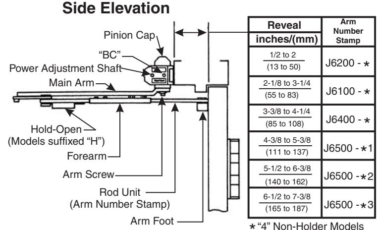
* "4" Non-Holder Models "7" Hold-Open Models
Cover
Thread in screws before mounting closer. Leave enough gap between the head of the screw and the closer to slide the cover on. Slide the cover over the closer and secure the mounting screws after the closer has been mounted and adjusted.
Aluminum Openings
Hold-Open inches Stop mm. 85° 90° 9-1/8 232 8-3/8 213 95° 100° 7-3/4 197 100° 7-3/8 187 105° 105 6-3/4 171 110° 165 110° 115° 6-1/2
Dimension "A"
Installation Sequence
- This page for installation on aluminum doors and frames only.
- Select door opening angle using template above. Mark 4 holes on frame face for closer and 2 holes on door for arm foot.
- Prepare door and frame for fasteners. See "Preparation for Fasteners" at bottom of page 2.
- 51 and 51BF Models Only. Set closing power using "Power Adjustment Chart" below.
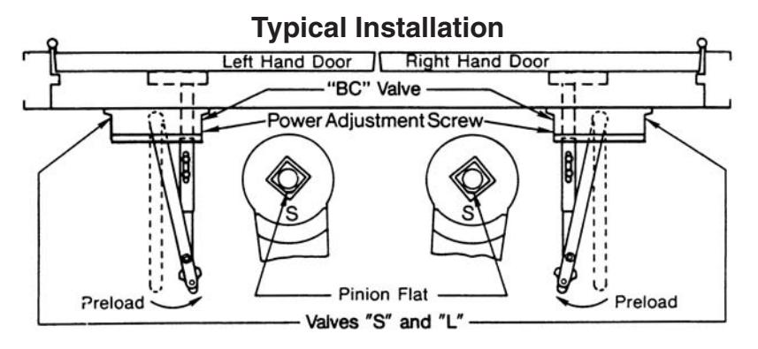
- Install closer to frame face with 2 regulating valves toward hinge edge of door.
- Remove rod unit from arm assembly.
- Install main arm onto closer pinion shaft, indexing main arm mark "S" with pinion flat as shown at right. Fasten with arm screw.
- Mount arm foot to door. Position foot with rod on bottom.
- Reassemble arm. Adjust forearm perpendicular (at a 90° angle) to door. Tighten rod screws.
- Snap pinion cap in place.
- Adjust closer.
Opening
* "4" Non-Holder Models "7" Hold-Open Models
| Power Adjustment Chart | ||||||||
|---|---|---|---|---|---|---|---|---|
| DOOR | TOP JAMB | * | MAXIMUM DOOR SIZE 34" | 36" | 40" | 44" | 48" | |||||
| DOON | INSTALLATION |
34"
(0.85M) |
(0.90M) | (1.00M) |
44"
(1.10M) |
48"
(1.20M) |
||
| INT | 51BF |
360° TURNS OF
DJUSTMENT SHAFT |
1 | 1 | 2 | 3 | 3 | |
| EXT | 3166 | 5 | 6 | 8 |
NOT
RECOMMENDED USE 51 |
|||
| INT | 51 | _ı ∢ | 2 | 4 | 6 | 9 | 11 | |
| EXT | 31 | FUL | 3 | 5 | 7 | 10 | 13 | |
| ★18 - 360° TURNS MAXIMUM AVAILABLE | ||||||||
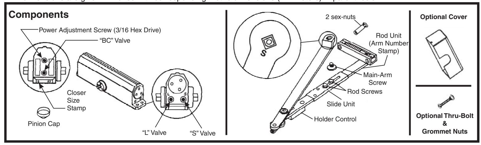
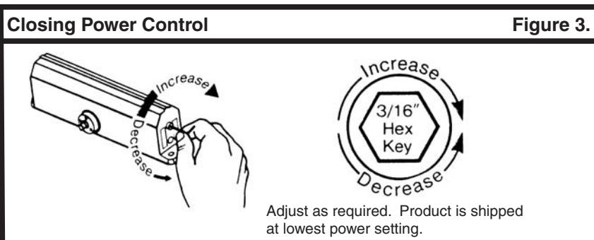
Unit Adjustment
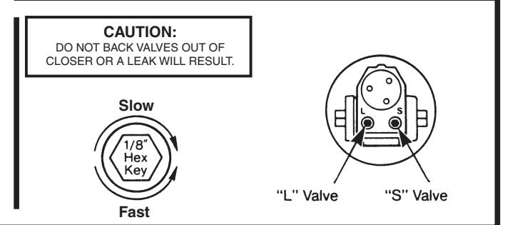
Closing Speed Controls
- Valve "S" Controls Sweep Range
- Valve "L" Controls Latch Range
Attention: Adjust Closing Speed Time to between 4 to 7 seconds from . Use of the door by handicapped, elderly or small children may require greater closing time. ADA code requires that door take at least 3 seconds to close from of door opening to within 3" (75mm.) of the closed position.
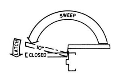
Standard Closing Cycle
Figure 1.
Figure 2.
NOTE: By law the Americans with Disabilities Act (ADA) may require that door closer installation comply with accessability guidelines.
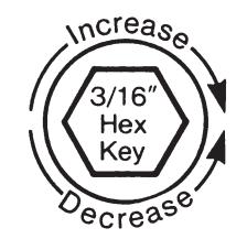
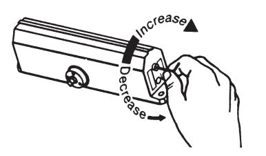
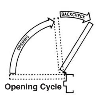
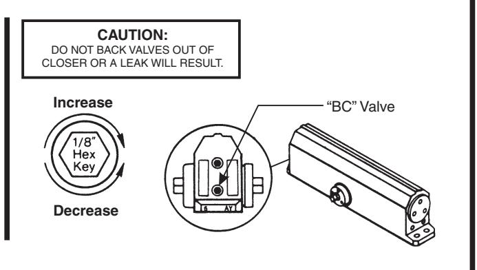
Opening Door Control
• Backcheck ("BC") valve controls the hydraulic resistance to door opening in backcheck range. NEVER close this valve completely - it is not to provide a positive stop.
| ٦ | Power Adjustment Chart | ||||||||
|---|---|---|---|---|---|---|---|---|---|
| PARALLEL ARM | * | MAXIMUM DOOR SIZE | |||||||
| DOOR | INSTALLATION |
34"
(0.85M) |
36"
(0.90M) |
40"
(1.00M) |
44"
(1.10M) |
48"
(1.20M) |
|||
| ı | INT. | T IE1DE |
FULL 360° TURNS OF
POWER ADJUSTMENT SHAFT |
2 | 2 | 3 | 4 | 5 | |
| ı | EXT. | TJ51 | 8 | 9 | 12 |
NOT
RECOMMENDED USE TJ51 |
|||
| ı | INT. | 3 | 5 | 7 | 10 | 13 | |||
| EXT. | 5 | 7 | 10 | 14 | 16 | ||||
| ★ 18 - 360° TURNS MAXIMUM AVAILABLE | |||||||||
Yale ® is a registered trademark of Yale Security Inc., an ASSA ABLOY Group company. Copyright © 1999, 2009, Yale Security Inc., an ASSA ABLOY Group company. All rights reserved. Reproduction in whole or in part without the express written permission of Yale Security Inc. is prohibited.

Tel: (800)-438-1951 • Fax: (800)-338-0965 www.yalecommercial.com