ASSA ABLOY ACCENTRA UNI-50 Series, Unitrol Parallel Arm, Non-Hold Open and Hold Open Installation_80-9350-2514-010
Open the original PDF document
View PDFYale <sup>®</sup>
Installation Instructions
80-9350-2514-010 (07-09)
Non Hold Open (UL Listed) Hold Open (H) (Not UL Listed)
UniTrol® Door Controls UNI-50BC Series Sized Closers UNI-51(BF) Series Multi-Sized Closers
An incorrectly installed or improperly adjusted door closer can cause property damage or personal injury. These instructions should be followed to avoid the possibility of misapplication or misadjustment.
Sized Multi-Sized (Sizes 2, 3, 4, 5, 6) UNI-52BC(H) UNI-53BC(H)
UNI-54BC(H) UNI-55BC(H) UNI-56BC(H) UNI-56BC(H)
MY Habitat for Humanity®
"DL" suffix (Delayed Action) is an optional feature. A separate instruction will be packed with these instructions, showing valve locations and adjustment procedures.
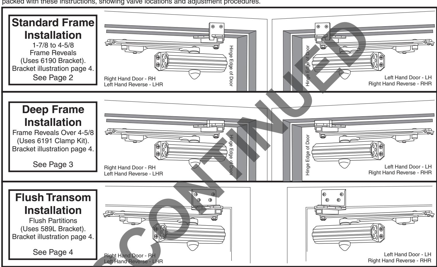
NOTE: For special applications a separate door and frame preparation template is packed with these instructions Use this instruction sheet for installation sequence and closer adjustments only
- · It is recommended that the door on which the door closer will be installed be hung on ball bearing hinges. Door must swing freely
- · Door and Frame must be properly reinforced, or use of special fasteners employed, to prevent the mounting screws from pulling out.
- All dimensions are given in inches with corresponding metric dimensions (mm) in parenthesis.
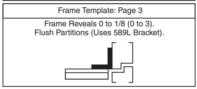
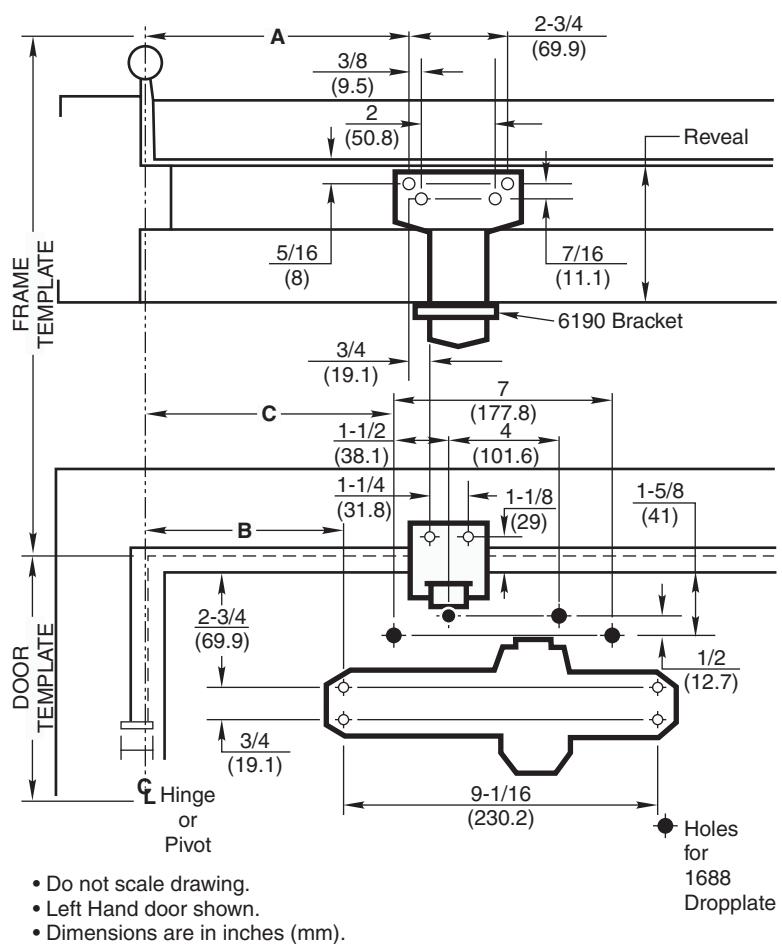
Template Information
- Door template is typical for all installations.
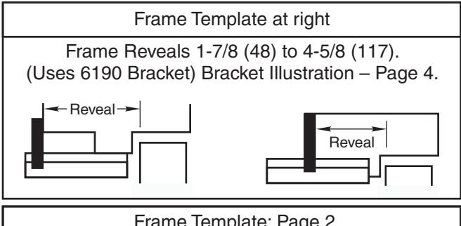
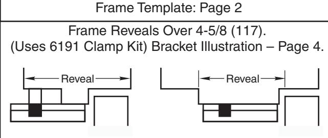
- Frame template must be selected according to frame reveal:
| Dimensions for Doors 28" to 32" Wide | ||||||||||
|---|---|---|---|---|---|---|---|---|---|---|
| Opening | Dimension A | Dimension B | Dimension C | |||||||
| Hold Open | Stop | Inches mm. | Inches | mm. | Inches | mm. | ||||
| 85° | 90° | 10-1/2 | 267 | 8-5/8 | 219 | 9-5/8 | 244 | |||
| 90° | 95° | 9-3/4 | 248 | 8 | 203 | 9 | 229 | |||
| 95° | 100° | 9-1/4 | 235 | 7-1/2 | 191 | 8-1/2 | 216 | |||
| 100° | 105° | 8-7/8 | 225 | 7-1/8 | 181 | 8-1/8 | 206 | |||
| 105° | 110° | 8-1/2 | 216 | 6-3/4 | 171 | 7-3/4 | 197 | |||
| 110° | 115° | 8-1/8 | 206 | 6-3/8 | 162 | 7-3/8 | 187 | |||
| Dimensions for Doors 33" to 41" Wide | ||||||||||
|---|---|---|---|---|---|---|---|---|---|---|
| Opening | Dimension A | Dimension B | Dimension C | |||||||
| Hold Open | Stop | Inches | Inches mm. | mm. | Inches | mm. | ||||
| 85° | 90° | 12-5/8 | 321 | 11 | 279 | 12 | 305 | |||
| 90° | 95° | 12 | 305 | 10-3/8 | 264 | 11-3/8 | 289 | |||
| 95° | 100° | 11-3/8 | 289 | 9-3/4 | 248 | 10-3/4 | 273 | |||
| 100° | 105° | 10-7/8 | 276 | 9-1/4 | 235 | 10-1/4 | 260 | |||
| 105° | 110° | 10-3/8 | 264 | 8-3/4 | 222 | 9-3/4 | 248 | |||
| 110° | 115° | 10 | 254 | 8-3/8 | 213 | 9-3/8 | 238 | |||
| Dimensions for Doors 42" to 48" Wide | ||||||||||
|---|---|---|---|---|---|---|---|---|---|---|
| Opening | Dimension A | Dimension B | Dimension C | |||||||
| Hold Open | Stop | Inches mm. | Inches | mm. | Inches | mm. | ||||
| 85° | 90° | 15 | 381 | 13-1/4 | 337 | 14-1/4 | 362 | |||
| 90° | 95° | 14-1/4 | 362 | 12-1/2 | 318 | 13-1/2 | 343 | |||
| 95° | 100° | 13-5/8 | 346 | 11-7/8 | 302 | 12-7/8 | 327 | |||
| 100° | 105° | 13 | 330 | 11-1/4 | 286 | 12-1/4 | 311 | |||
| 105° | 110° | 12-1/2 | 318 | 10-3/4 | 273 | 11-3/4 | 298 | |||
| 110° | 115° | 12 | 305 | 10-1/4 | 260 | 11-1/4 | 286 | |||
Door Template Typical for All Installations Frame Template for 1-7/8 to 4-5/8 Reveals
| Preparation for Fasteners | ||||||||
|---|---|---|---|---|---|---|---|---|
| Fasteners | Door or Frame | Drill-Sizes | ||||||
| Solf Drilling Sorow |
Aluminum
or Metal |
No drill required | ||||||
| Self-Drilling Screw | Wood |
3/16" (4.30 mm)
Pilot hole required |
||||||
| 1/4" - 20 machine screw | Metal |
Drill: #7 (0.201" dia.)
Tap: 1/4" - 20 |
||||||
| Sleeve nuts and bolts |
Hollow
Metal |
9/32" (7 mm) through;
3/8" (9.5 mm) door face opposite to closer |
||||||
| Aluminum or Wood | 3/8" (9.5 mm) through | |||||||
| Power Adjustment Chart | |||||||||
|---|---|---|---|---|---|---|---|---|---|
| DOOR |
PARALLEL ARM
INSTALLATION |
44 | MAXIMUM DOOR SIZE | ||||||
| * |
34"
(0.85 m) |
36"
(0.9 m) |
40"
(1 m) |
44"
(1.1 m) |
48"
(1.2 m) |
||||
| INT |
JRNS
USTMENT |
2 | 2 | 3 | 4 | 5 | |||
| EXT | 51BF |
FULL 360° TURNS
OF POWER ADJUSTIV SHAFT |
8 | 9 |
NOT
RECOMMENDED USE 51 |
||||
| INT | F4 | 3 | 5 | 7 | 10 | 13 | |||
| EXT | 51 | 5 | 7 | 10 | 14 | 16 | |||
| *18 -360° TURNS MAXIMUM AVAILABLE | |||||||||
Page 2 80-9350-2514-010 (07-09)
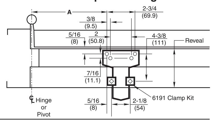
Frame Template for Reveals Over 4-5/8 Door Template on Page 2
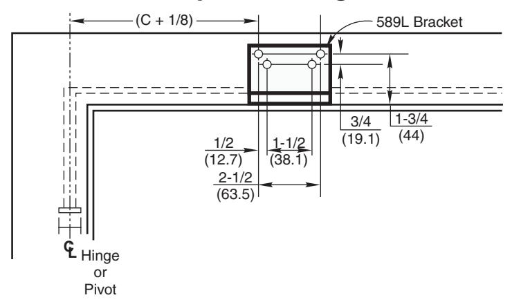
Frame Template for Flush Partitions Door Template on Page 2
Typical Installation Left Hand Door "S" and "L" Valves Pinion Flat Right Hand Door "S" and "L" Valves Pinion Flat Pinion Flat Main Arm Hold-Open "S" Valve "L" Valve Pinion Cap
Installation Sequence
Read Front Page.
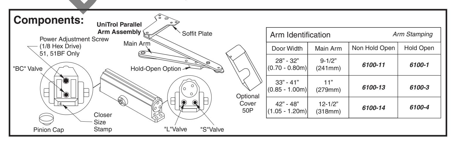
Installations and component identification are on this page. Arm assembly must be correct for width of door, see chart.
Select Correct Door and Frame Template Combination.
Follow "Template Information" on Page 2 or Pages 2 and 3.
Mark Location of Mounting Holes.
Use dimensions for hold-open or door stop angle desired. Mark position of 4 holes on door for closer (or drop plate) and 6 holes on frame for soffit plate (or 4 for 589L angle bracket).
• Prepare Holes for Fasteners.
See "Preparation for Fasteners" chart on Page 2.
UNI51 or UNI51BF Models Only. Set approximate closing power using "Power Adjustment Chart" at bottom of Page 2.
Mount Closer to Door.
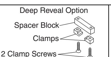
Drop Plate first, if used. Place end with "S" and "L" valves toward the lock edge of the door. If using optional cover see "Cover" instructions at bottom of Page 4.
• Mount Arm to Frame.
Fasten soffit plate (or 589L angle bracket if flush partition) to frame. Mount 6190 bracket or 6191 clamps to reinforce soffit plate.
Install Arm on Pinion Shaft.
Close valves "S" and "L". Rotate pinion over 45° to align main arm letter "R" (right hand) or "L" (left hand) with pinion flat. Fasten with arm screw. See "Typical Installation" figure above right. Re-open valves "S" and "L".
Screw pinion cap onto the pinion shaft by hand or with a Phillips screw driver - DO NOT OVER TIGHTEN. Skip this step if optional cover is used.
Adjust Closer.
See "Unit Adjustment" on Page 4.
Unit Adjustment
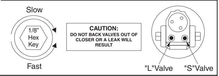
Closing Speed Control
Valve "S" controls Sweep Range.
Valve "L" controls Latch Range.
Attention: Adjust Closing Speed Time to between 4 to 7 seconds from . Use of the door by handicapped, elderly or small children may require greater closing time. ADA code requires that door take at least 3 seconds to close from 70° of door opening to within 3" (75mm) of the closed position.
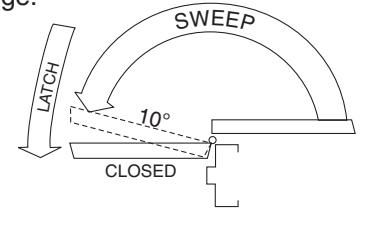
Closing Cycle
NOTE: By law the Americans with Disabilities Act (ADA) may require that door closer installation comply with accessability quidelines.
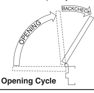
Opening Door Control
Figure 2
Figure 1
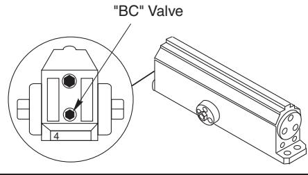
• Backcheck ("BC") valve controls the hydraulic resistance to door opening in backcheck range. NEVER close this valve completely – it is not to provide a positive stop.

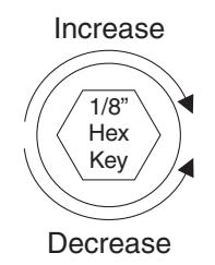
Closing Power Control
Figure 3
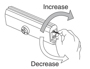
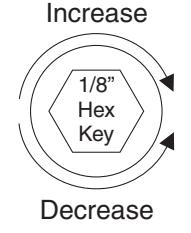
Adjust as required. Product is shipped at mid range power setting.
Power Adjustment Chart
| PARALLEL ARM | -1- | MAXIMUM DOOR SIZE | ||||||||
| DOOR | INSTALLATION | * |
34"
(0.85 m) |
36"
(0.9 m) |
40"
(1 m) |
44"
(1.1 m) |
48"
(1.2 m) |
|||
| INT |
NS
TMENT |
2 | 2 | 3 | 4 | 5 | ||||
| EXT | 51BF |
FULL 360° TURNS
OF POWER ADJUSTI SHAFT |
8 | 9 |
NOT
RECOMMENDED USE 51 |
|||||
| INT | 51 | 3 | 5 | 7 | 10 | 13 | ||||
| EXT | 5 | 7 | 10 | 14 | 16 | |||||
*18 -360° TURNS MAXIMUM AVAILABLE
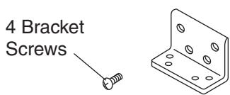
Bracket Illustrations
Standard 6190 Bracket
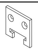
No. 6191 Reinforcing Kit
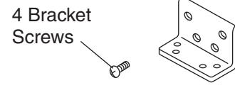
Flush Partition Option
No. 589L Bracket
Cover (Optional Cover 50P)
Thread in screws before mounting closer. Leave enough gap between the head of the screw and the closer to slide the cover on. Slide the cover over the closer and secure the mounting screws after installation is complete.
To identify your model: 3 - 6 = 512=52BC 3=53BC 1-4=51BF 4=54BC 5=55BC Size -Date 6=56BC Code Code
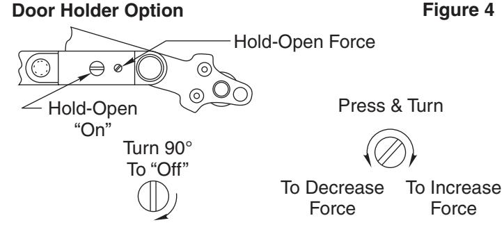
Hold-Open option is found at the arm elbow. To select hold-open "on" or hold-open "off" and to adjust the holdopen force ... use screwdriver as illustrated.

Yale ® is a registered trademark of Yale Security Inc., an ASSA ABLOY Group company. Copyright © 1999, 2009, Yale Security Inc., an ASSA ABLOY Group company. All rights reserved. Reproduction in whole or in part without the express written permission of Yale Security Inc. is prohibited.