ASSA ABLOY ACCENTRA Support Unit – PT, Slave Unit – PTS (Push Side) Installation Instructions_80-9344-0710-010
Open the original PDF document
View PDFYale
Installation Instructions
80-9344-0710-010 (7-01)
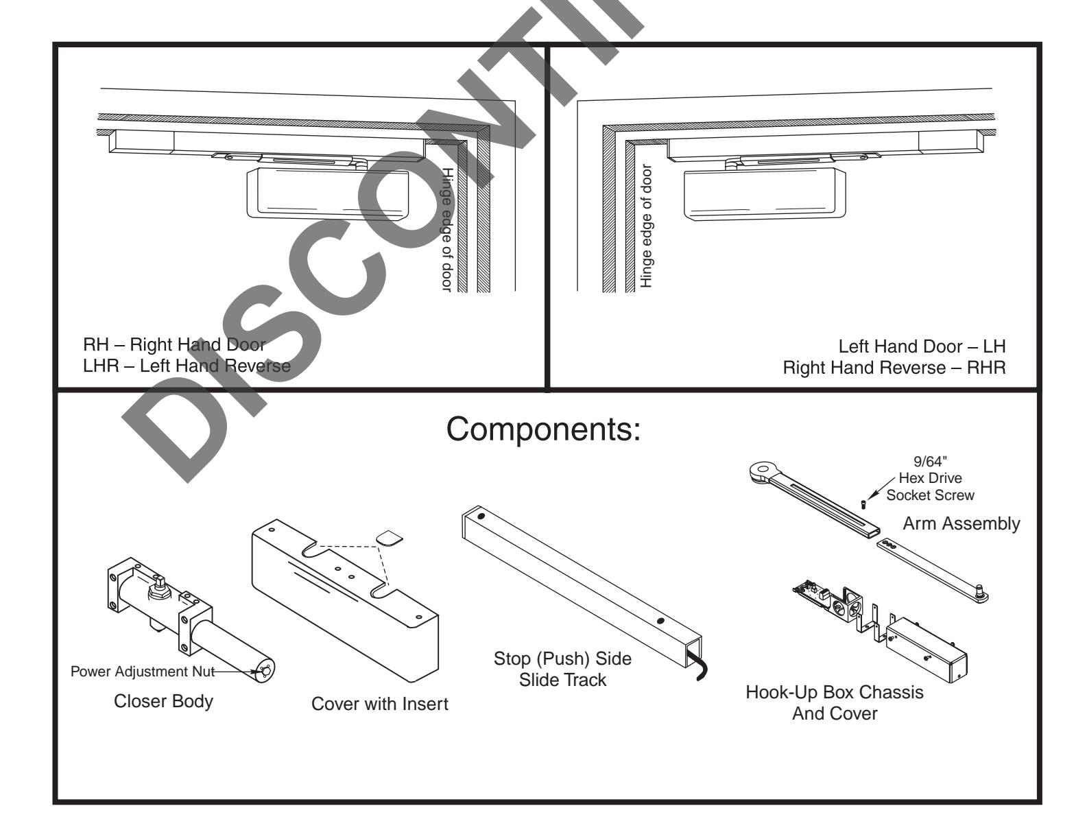
Combination Door Closer-Holder and Releasing Device WITHOUT Integral Smoke Detector
Power Track Series Support Unit – PT Slave Unit – PTS
Models
Stop (Push) Side of Door Application
Support P400 PT
Slave P400 PTS
CAUTION
An incorrectly installed or improperly adjusted door closer can cause property damage or personal injury. These instructions should be followed to avoid the possibility of misapplication or misadjustment.
NOTE: For special applications a separate door and frame preparation template is packed with these instructions. Use this instruction sheet for installation sequence and closer adjustments only.
• Use of an auxiliary door stop is always recommended.
| N | ΓE | 9 |
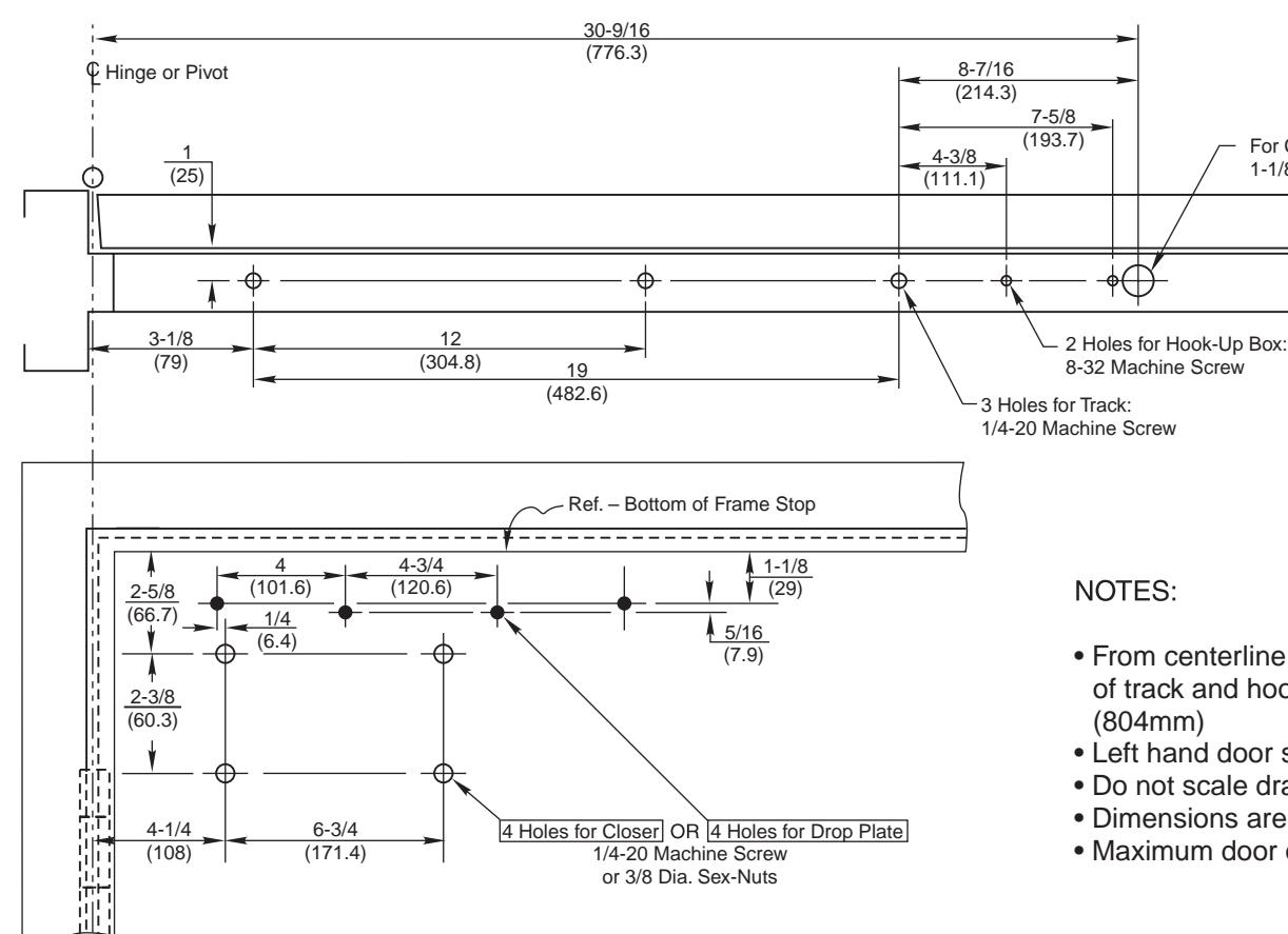
• From centerline of pivot point to end of track and hook-up box is 31-21/32 (804mm)
For Concealed Wiring Only 1-1/8 (29) Hole for Conduit
- Left hand door shown
- Do not scale drawing
- Dimensions are given in inches (mm)
- Maximum door opening is 110°
| Fasteners | Opening | Fastener Preparation | |||
| 8-32 Machine Screw | Metal Frame |
Drill: #29 [.136" (3.45mm) dia.]
8-32 UNC Tap |
|||
| 1/4-20 Machine Screw |
Metal
Door or Frame |
Drill: #7 [.201" (5.10mm) dia.]
1/4"-20 UNC Tap |
|||
| 3/8 Dia. Sex Nut |
Wood or
Composite Door |
3/8" [.375" (9.50mm) dia.]
through |
|||
- 1. Locate and drill 1-1/8" (29mm) diameter hole in frame soffit for the conduit.
-
2. using above template:
- holes for or holes for . holes for
- 3. using "Preparation for Fasteners" chart above.
- 4. with wires toward lock edge of frame and open side facing down.
- 5. from Hook-Up Box assembly.
- 6. with conduit hole openings away from hinge edge of frame. Place Hook-Up Box straps between frame and chassis. Special conduit nut supplied to anchor 3/4" conduit fitting.
-
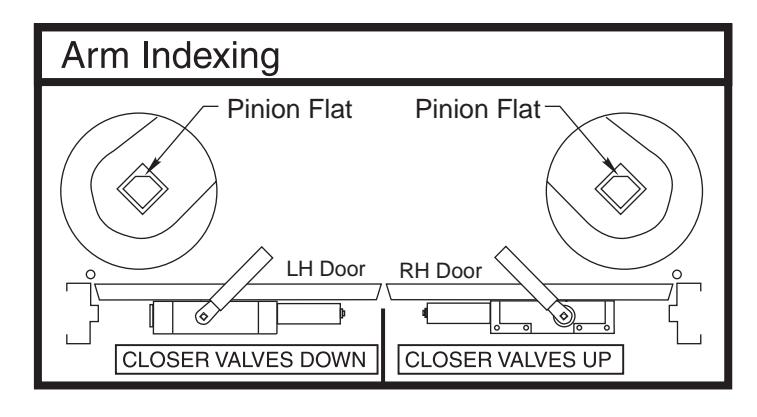
7. ith spring adjustment nut toward lock edge of door and closer valves: w
- Facing for door Facing for door
- 8. and install 9/64" hex drive socket head screw from screw pack.
- 9. using Arm Indexing instructions above.
- 10.
- 11. in track assembly. Secure by pushing in on the retainer clip that extends from the slide block in the track, until it is flush with the slide block.
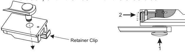
Attaching Arm Stud to Slide
80-9344-0710-010 (7-01)
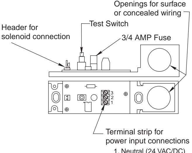
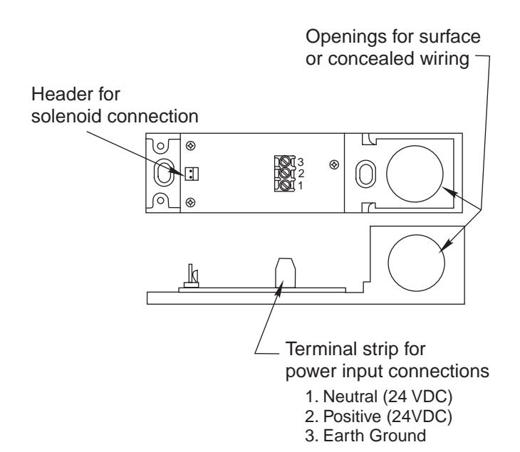
MAKE ELECTRICAL CONNECTIONS
- Select the proper wiring diagram from Page 4 and make input power connections to the hook-up box terminal strip. Note 14AWG maximum wire size for connections.
- 2. Connect solenoid to hook-up box:
A. 24V units are supplied with a "keyed" solenoid connector that plugs into a header on the hook-up box board.
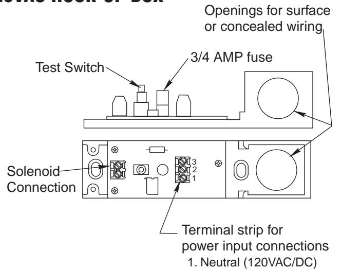
B. 120V units are supplied with a 2 connector terminal strip on the hook-up box board for making the solenoid connection.
DOOR CLOSER ADJUSTMENTS
Arm Attachment to Track
Insert arm stud into slide block in track.
Secure by pushing in on the retainer clip that extends from the slide block, until it is flush with the slide block, see illustration on page 2 of these instructions.
Hold Open Angle:
Place door in the Hold Open position. Remove 9/64" hex drive socket head screw from arm. Open door to desired angle and install hex-drive socket head screw into hole in adjusting rod that is aligned with the hole in the adjusting tube.
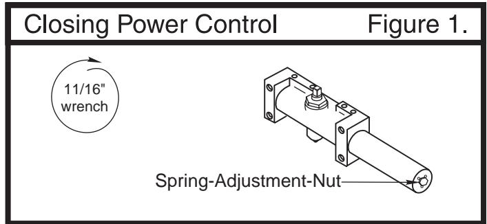
Closing Power
Closing Power can be increased by 50%.
To increase power, see Figure 1, rotate "Spring Adjustment Nut clockwise using a 11/16" wrench or socket. 15 full turns (360°) will provide maximum available power.
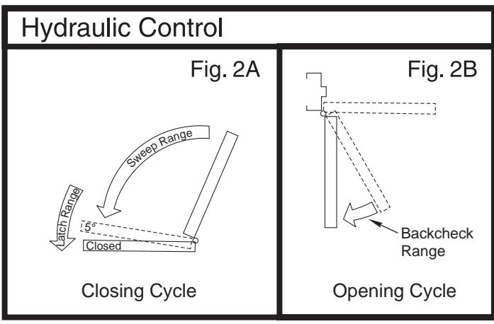
Closing Cycle (hydraulic control)
See figure 2A.
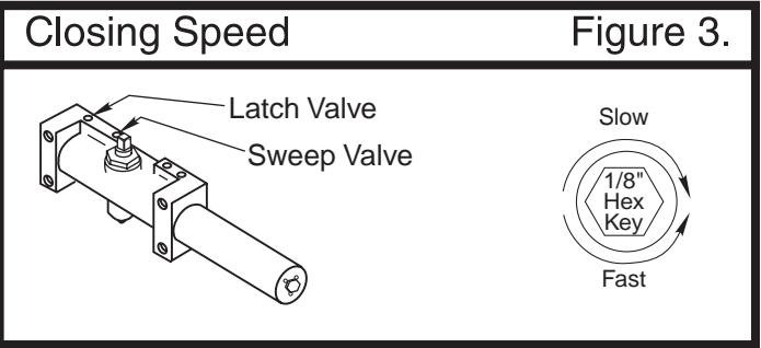
Valve "L" controls door speed in Latch range.
Valve "S" controls door speed in Sweep range.
Use 1/8" hex-key furnished and adjust as shown in figure 3.
Opening Cycle (hydraulic control)
See figure 2B.
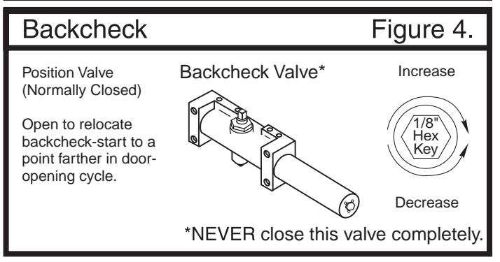
Valve "B" cushions (slows) door opening in the backcheck range.
Note: Never close this valve completely or damage to closer may occur.
Valve "P" allows "backcheck" to begin later in the opening cycle.
Use 1/8" hex-key furnished and adjust as shown in figure 4.
Installation of Cover:
Fasten cover to closer with two screws provided:
- Molded Cover fastened at the top of closer.
- Metal Cover fastened at each end of closer.
Using four screws provided, fasten metal hook-up box cover.
Hold Open Power Adjustment:
If more hold open power is required, the power may be increased by turning the adjustment screw in the end of the track nearest the hinges. Use 9/64" hex wrench provided and rotate adjustment screw clockwise to increase holding power.
- 3. Turn the power to the unit "On".
- 4. Open door to the hold open point. The door should hold open.
5a. "PT" Units Only
Depress "Test Switch" button on hook-up box board ... door should close.
5b. "PTS" Units Only
Depress "Test Switch" button on MASTER UNIT hookup box board ... both master and slave door should close.
"PT" WIRING INSTRUCTION 24VAC/DC or 120VAC
Input voltage supplied must match label rating on hook-up box.
TYPICAL WIRING DIAGRAM TYPICAL WIRING DIAGRAM
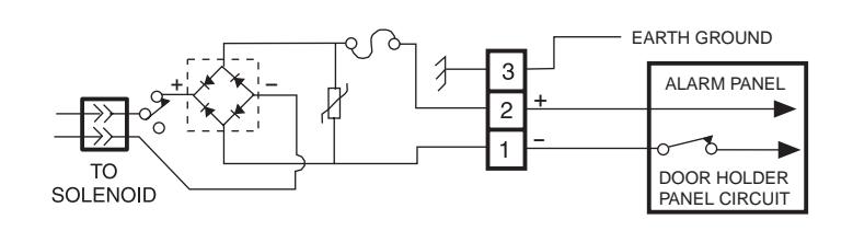
24VAC/DC HOOK-UP BOX HOOK-UP BOX
- 1. Neutral (24 VAC/DC)
- 2. Positive (24VAC/DC)
- 3. Earth Ground
2. Positive (120VAC/DC) 3. Earth Ground
120VAC HOOK-UP BOX
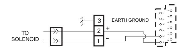
"PTS" WIRING INSTRUCTION 24VDC ONLY
Typical wiring terminals 1 and 2 will connect to terminals 5 and 6 from "PTD" unit
SPECIFICATIONS:
| 120VAC + 10%-15% | 24VAC + 10%-15% | 24VDC + 10% -15% |
| .018 AMPS | .090 AMPS | .090 AMPS |
NOTES: 1. Maximum wire size is 14AWG.
2. All wiring and connections use standard wiring practice conforming with local wiring codes.