ASSA ABLOY ACCENTRA Sectional Trim and V Series Indicators for 8800 Series Mortise Locks Installation Instructio…_80-8800-0016-000
Open the original PDF document
View PDF

Installation Instructions
Instructions for Wiring 8800 Series Electrified Mortise Solenoid Locks, 8800 Series Monitoring Suffixes REX, LBM and DBM and Combined Solenoid and Monitoring Suffixes with Pluggable ElectroLynx® Connector System.

Installation Instructions
Table of Contents
| 1. Tools Required | 2 |
|---|---|
| 2. Indicator Variants | 2 |
| 3. Lock Set Configuration | 3 |
| 4. Rehanding Indicator (if required) | 3 |
| 5. Installation | 4 |
| 1. Prepare Door for Mortise Lock | 4 |
| 2. Install Lock | 4 |
| 3. Prepare Door for Indicator | 4 |
| 4. Install Levers 5 | |
| 5. Install Indicator Mounting Plate | 5 |
| 6. Install Indicator Assembly 5 | |
| 7. Install Cylinder | 6 |
| 8. Install Outside Front | 6 |
| 9. Perform Functional Check | 6 |
| 6. Indicator Part List | 7 |
1. Tools Required
#2 & #3 Phillips Head Screwdrivers

Wrench

3/32" Drill Bit T-20 Torx Screw with Tamper Pin Driver
2. Indicator Variants
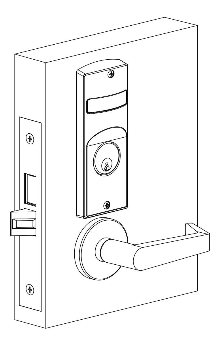
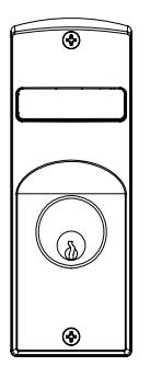
Depending on function and option ordered, indicators are provided in the following variations. These instructions detail how to install with cylinder, however other variations follow similar instructions (Figure 1).
Contact factory for any questions.
Figure 1
Flat Blade Screwdriver 1/8" Allen

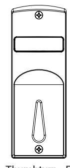
Thumbturn - For Installation on Inside of Door
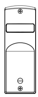
Coin Turn - For Installation on Outside of Door
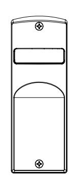
No input/blank - For Installation on Inside or Outside of Door
Installation Instructions
3. Lock Set Configuration
To re-hand lock, see instructions on lock body.
4. Rehanding Indicator (If required)
Verify hand and bevel of door (Figure 2).
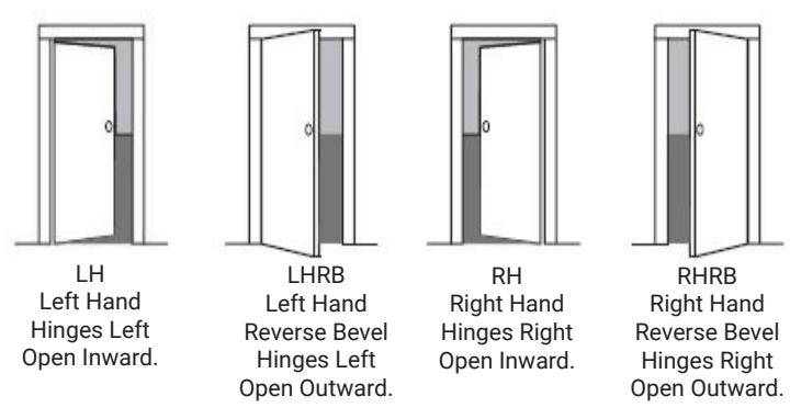
NOTE: Stand on outside of locked door when determining door hand.
Next, verify inside and/or outside indicators are handed correctly, using Spindle Cam Position chart (Figure 3). If they are handed correctly, skip to Step 5 "Prepare Door".
If they are not handed correctly:
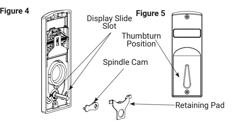
- 1. Remove retaining pad and spindle cam from assembly (Figure 4).
- 2. Position spindle cam in correct direction for door hand (Figure 3).
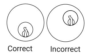
NOTE: For thumbturn indicators, make sure thumbturn is positioned in the 12 o'clock direction as shown (Figure 5).
- 3. Slide spindle cam post into correct slot of display slide (Figure 4).
- 4. Re-seat retaining pad into original position.
- 5. Rerurn indicator to the vacant/unlocked position for installation.
Figure 3 Spindle Cam Position for Locks with Deadbolt (*Includes 8864 function) Figure 2
Door Hand RH/RHRB


Spindle Cam Position for Locks without Deadbolt (*Does not include 8864 function)
Door Hand RH/RHRB


Door Hand LH/LHRB


Installation Instructions
5. Installation
1. Prepare Door for Mortise Lock
Prepare door for function holes, size, and location according to 7088-0006 door marker template, if not already prepped.
2. Install Lock
- Verify strike location according to template. Clean out door pocket and door edge of debris.
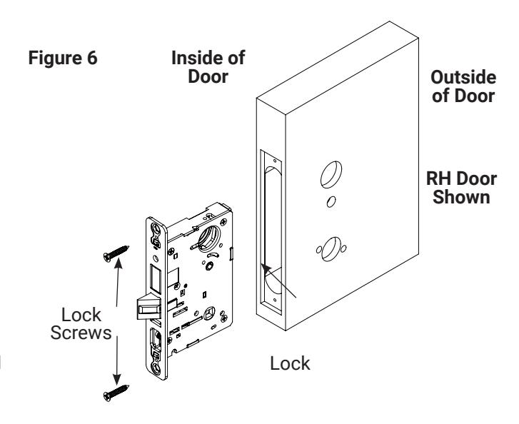
- 2. Make sure handing of lock matches handing of door. Slide lock into door (Figure 6).
- 3. Temporarily hand tighten two (2) lock screws (#12x1-1/4" wood screws, or #12-24x1/2" machine screws).
NOTE: Keep door open until installation is complete.
3. Prepare Door for Indicator
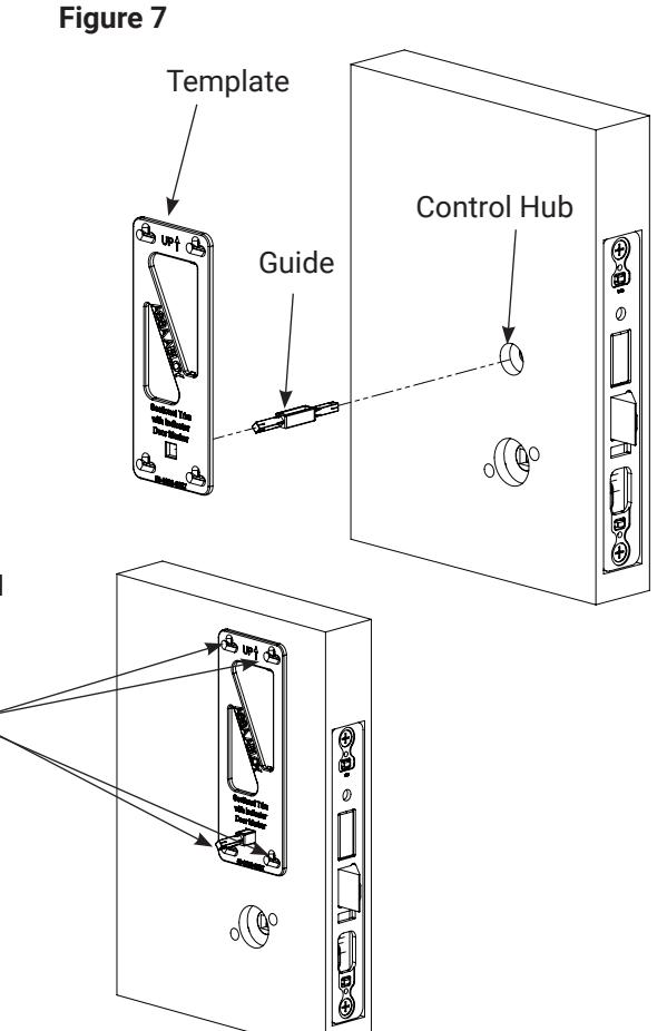
- 1. Insert template guide into control hub on side where indicator will be used (Figure 7).
- 2. Slide indicator template over template guide.
NOTE: Make sure the template is properly centered and aligned to ensure smooth indicator operation.
- 3. Mark the four (4) hole positions indicated on template.
- 4. Remove guide and template.
- 5. If indicators are being used on both sides of door, repeat steps 3.1 through 3.4 for opposite side.
- 6. Remove lock body.
- 7. Drill four (4) marked holes with 3/32" diameter bit, by 1/2" deep.
- 8. Reinstall lock body and hand tighten screws.
NOTE: If retrofitting over an existing product, ensure door surface is free of chips and debris around holes so indicator will sit flat against door surface.
80-8800-0016-000 04/24
Experience a safer and more open world
1-855-557-5078 Ext. 2 • www.accentra-assaabloy.com
Mark Holes with Pencil
8800 Series Mortise Lock
Used with Sectional Trim and V Series Indicators
Installation Instructions
5. Installation, continued
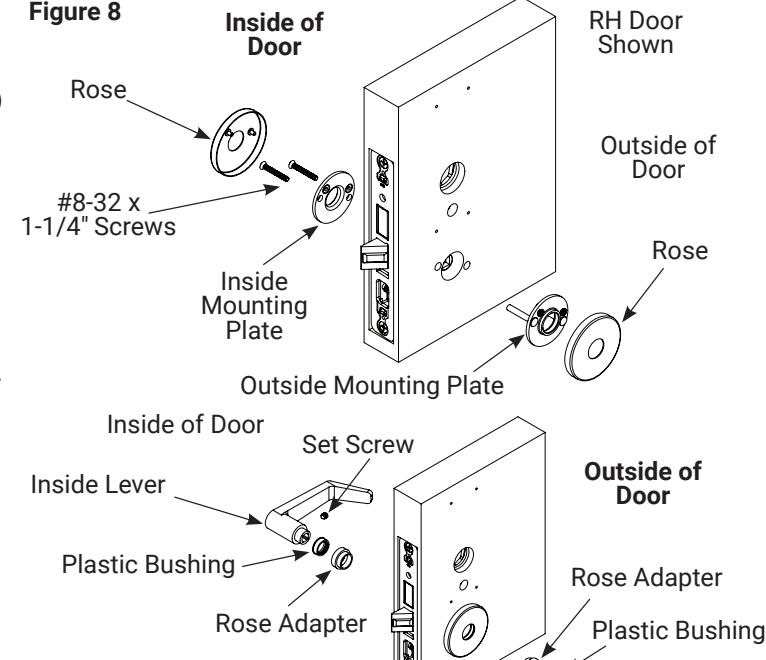
4. Install Levers
- 1. Insert outside mounting plate through door and lock body, and hold (Figure 8).
- 2. Align and fasten inside mounting plate securely with two (2) #8-32 x 1-1/4" screws.
- 3. Install roses on inside and outside adapter plates.
- 4. If included, press rose adapter into rose and mounting plate assemblies.
- 5. Unscrew inside spindle 1/2 turn and align ramp in the horizontal position.
- 6. Slide plastic bushing onto outside lever and spindle and insert through the lockbody.
- 7. Slide plastic bushing onto inside lever and attach to spindle. Then tighten inside lever set screw.
Outside Lever and Spindle
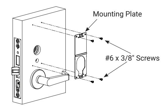
5. Install Indicator Mounting Plate
- 1. Align and fasten inside mounting plate securely with two (2) #8-32 x 1-1/4" screws.
- 2. If indicators are being used on both sides of door, repeat step 5.1 for opposite side.
Figure 9
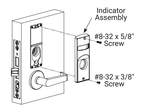
6. Install Indicator Assembly
- 1. Verify lock is in unlocked state (turn outside lever to confirm).
- 2. Verify indicator is in vacant/unlocked position.
- 3. Assemble indicator assembly onto mounting plate (Figure 10).
-
4. Secure indicator assembly to door with two (2) machine screws.
- Use #8-32 x 5/8" screw for top
- Use #8-32 x 3/8" screw for bottom
- 5. If indicators are being used on both sides of door, repeat steps 6.1 through 6.3 for opposite side.
NOTE: Torx security screws recommended.
Figure 10

Installation Instructions
5. Installation, continued
7. Install Cylinder
-
1. Thread cylinder into lock until flush with indicator escutcheon surface (Figure 11).
- Pull key slightly out of cylinder to help thread into lock body.
- Tighten cylinder clamp screw with #2 Phillips screwdriver.
- Check operation and adjust if necessary.
NOTES:
- Key and cylinder must be positioned as Figure 12 shows.
- If double cylinder function is used, repeat steps 7.1 and 7.2 for second cylinder.
- Interchangeable core cylinders require a control key to remove and install the core. This is not provided standard. It must be requested seperately.
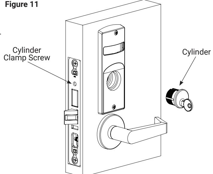
Figure 12
Key and cylinder must be rotated as shown.
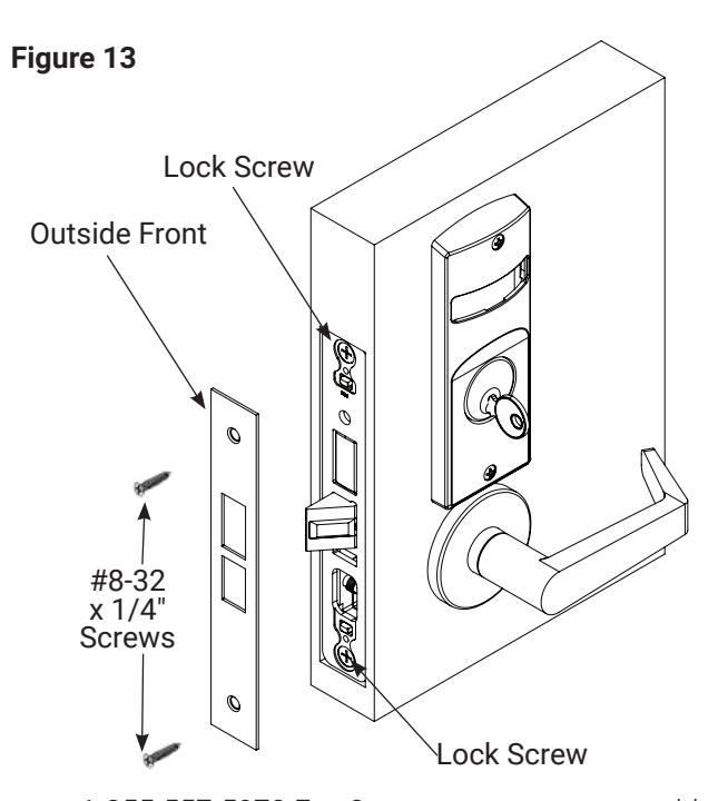
8. Install Outside Front
- Tighten the two (2) lock screws completely (Figure 13).
- 2. Attach outside front with two (2) flat head screws #8-32 x 1/4".
9. Perform Functional Check
DO NOT FORCE if resistance is encountered during functional check. Refer back to Rehanding Indicator (if required) section to ensure correct handing. Rehand if necessary.
-
Insert key into cylinder (if present) and rotate:
- Ensure there is no friction against lock case or any other obstructions.
-
Check key retracts latch:
- Key should rotate freely.
-
3. Throw deadbolt (if present):
- Check key retracts both deadbolt and latch
-
- Confirm latch and deadbolt (if installed) retract.
- 5. Verify indicator displays correct status when locked and unlocked.
80-8800-0016-000 04/24
Experience a safer and more open world
1-855-557-5078 Ext. 2 • www.accentra-assaabloy.com
Installation Instructions
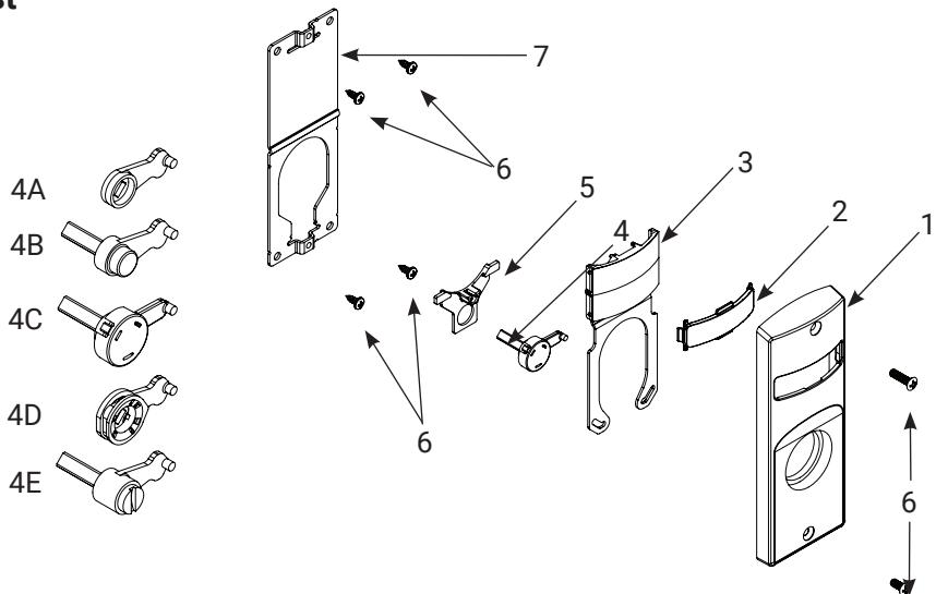
6. Indicator Parts List
| # | DESCRIPTION | PART # | REQ. |
|---|---|---|---|
| Sectional Escutcheon - Cylinder | 81-0472-4000 x finish | ||
| Sectional Escutcheon - Coin Turn | 81-0471-4000 x finish | ||
| 1 | Sectional Escutcheon - Thumbturn | 50-8800-0364 x finish | 1 |
| Sectional Escutcheon - No Input/Blank | 81-0473-4000 x finish | ||
| 2 | Indicator Window | 856F049 | 1 |
| Indicator Display Assembly - Green Unlocked / Red Locked | 82-5602-4000 | ||
| Indicator Display Assembly - Green Vacant / Red Occupied | 82-5603-4000 | ||
| Indicator Display Assembly - Green Unlocked Icon / Red Locked Icon | 82-5604-4000 | ||
| Indicator Display Assembly - White Unlocked / Red Locked | 82-5605-4000 | ||
| 3 | Indicator Display Assembly - White Vacant / Red Occupied | 82-5606-4000 | 1 |
| Indicator Display Assembly - White Unlocked Icon / Red Locked Icon | 82-5607-4000 | ||
| Indicator Display Assembly - Green Ouvert / Red Fermé | 82-5684-4000 | ||
| Indicator Display Assembly - Green Libre / Red Occupée | 82-5685-4000 | ||
| 4A | Indicator Spindle Cam - Thumbturn | 50-8800-9328 | |
| 4B | Indicator Spindle Cam - Cylinder/No Input / Blank | 50-8800-7335* | |
| 4C | Indicator Spindle Cam - Cylinder Overtravel | 50-8800-0378* | 1 |
| 4D | Indicator Spindle Cam - Thumbturn Overtravel | 50-8800-0346 | |
| 4E | Indicator Spindle Cam - Coin Turn | 50-8800-7339* | |
| 5 | Indicator Retaining Pad | 81-0749-9000 | 1 |
| 6 | Sectional Indicator Screw Pack | 85F497 FIN* | 1 |
| 7 | Sectional Indicator Mounting Plate | 855F658 | 1 |
| 8 | Sectional Indicator Template Kit (not shown) | 50-8800-9343 | 1 |
* These parts are for 1-3/4" standard thickness doors. For other thicknesses, contact the factory.
NOTE: Reference 8800 Series parts manual for all lock body parts.
1-855-557-5078 Ext. 2 • www.accentra-assaabloy.com