ASSA ABLOY ACCENTRA SDA16 Stand-Alone Alarm Device Installation Instructions_80-9470-0330-000
Open the original PDF document
View PDF

SDA16 Stand-Alone Alarm Device Installation Instructions
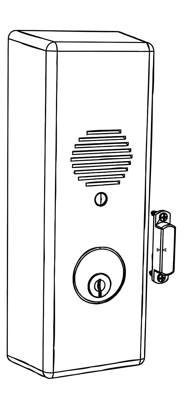
EMERGENCY EXIT - ALARM WILL SOUND

1. Frame and Door Preparation
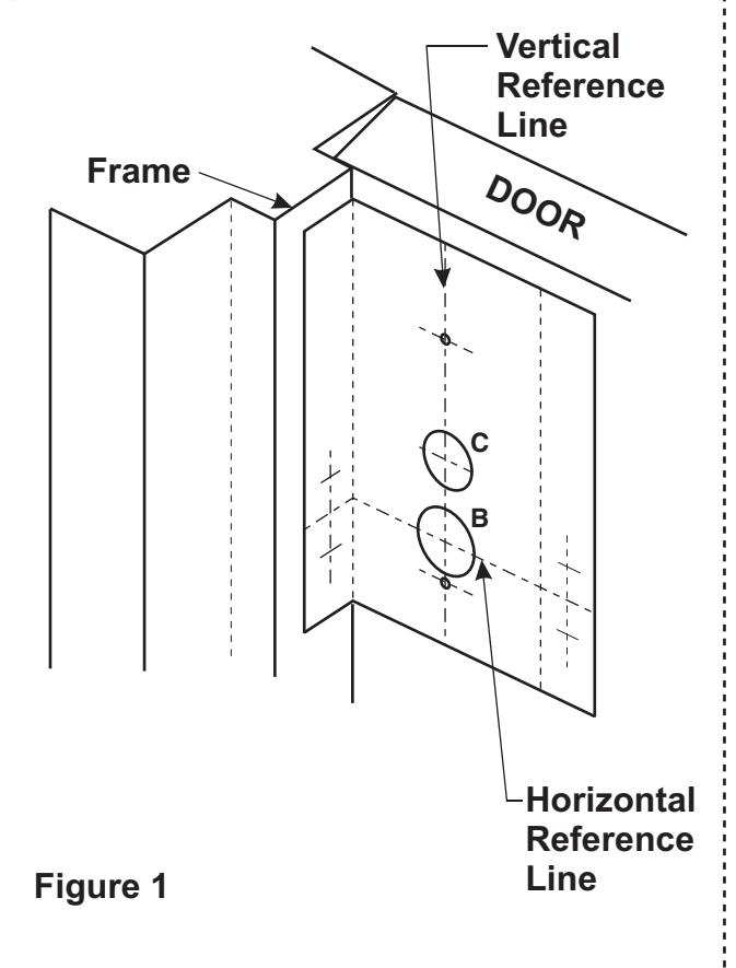
Out-swinging Door
- For installation on an Out-swinging Door, mark a Vertical Reference Line 2-3/16"(56mm) off of the Frame Stop, also decide the vertical placement on the door and mark a Horizontal Reference Line. Fold template as shown and align with Vertical and Horizontal Reference Lines.
- 2. Use a center punch to mark door for (2) .144"(3.7mm) Dia. (#27 Drill) mounting holes for the Device Mounting Base (Shown Below).
- 3. Use a center punch to mark frame for (2) .099"(2.5mm) Dia. (#39 Drill) holes for the Magnet (Shown Below).
- If outside Cylinder Control Option is to be used, bore a 1-1/4"(32mm) Dia. Hole thru door. Fig. 1 'B' Hole
- For Hardwire option requiring door preparation, mark and bore a 1"(25mm) Dia. Hole to required depth. Fig. 1 'C' Hole
- 6. Install Magnet to door frame with (2) #4 screws supplied.
Arrows on the magnet face toward the alarm housing and away from the door.
In-swinging Door
- For installation on an In-swinging Door, mark a Vertical Reference Line 1-15/16"(50mm) off of the Frame Edge, also decide the vertical placement and mark a Horizontal Reference Line. Align template as shown with Vertical and Horizontal Reference Lines.
- Use a center punch to mark door for (2) .144"(3.7mm) Dia. (#27 Drill) mounting holes for the Device Mounting Base (Shown Below).
- 3. Use a center punch to mark frame for (2) .099"(2.5mm) Dia. (#39 Drill) holes for the Magnet (Shown Below).
- If outside Cylinder Control Option is to be used, bore a 1-1/4"(32mm) Dia. Hole thru door. Fig. 2 'B' Hole
- 5. For Hardwire option requiring door preparation, mark and bore a 1"(25mm) Dia. Hole to required depth. Fig. 2 'C' Hole
- 6. Install Magnet to door frame with (2) #4 screws supplied.
Arrows on the magnet face toward the alarm housing and away from the door.
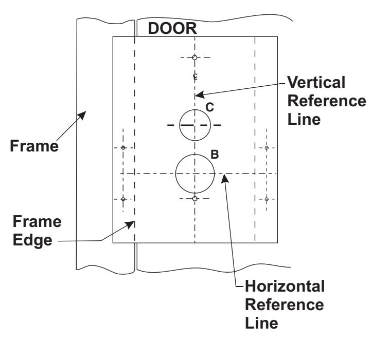
Figure 2
2
2. Installing Cylinder
- 1. Insert mortise cylinder through hole in the Housing.
- 2. Orient keyway to the 6 o'clock position, adjust as needed.
- Assemble cylinder actuator onto the cylinder from inside as shown below. The split tabs should be oriented towards the controller board (12 o'clock position), trapping the toggle switch on the printed circuit board. Fig. 4
Caution: Carefully install Actuator without damaging the Toggle Switch.
4. Attach cylinder nut to cylinder, rotate clockwise until secure. NOTE: Actuator should be free to rotate, by installing in
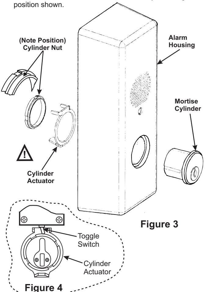
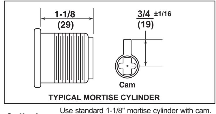
Cylinder Collar is not required. Use standard 1-1/8" mortise cylinder with cam Cylinder Collar is not required.
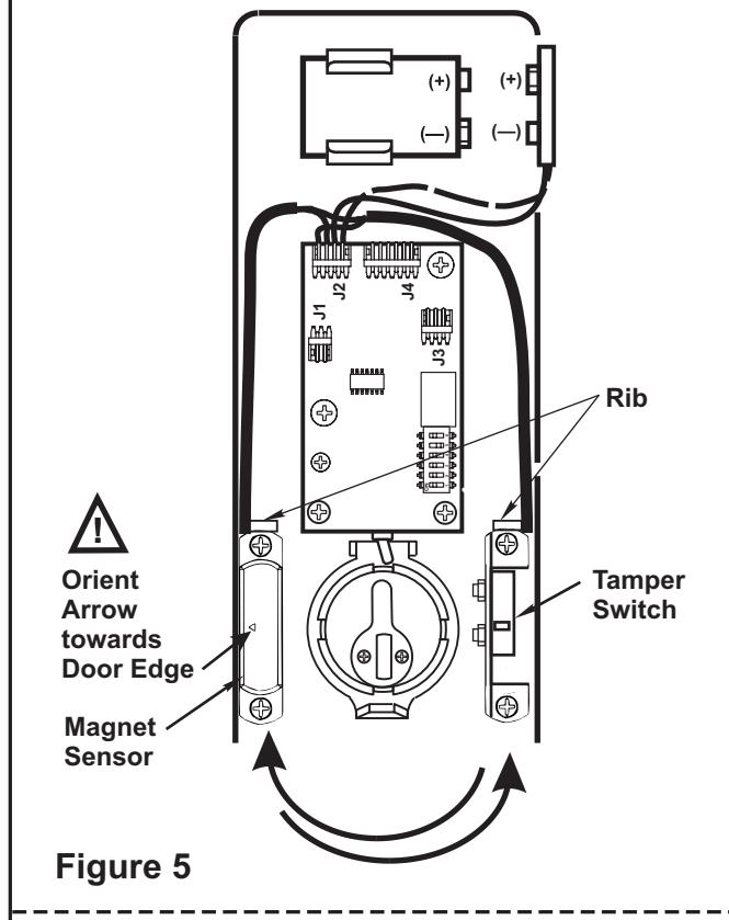
3. Device Handing Change
- Remove (2) screws retaining the magnet sensor and set components aside.
- Remove (2) screws retaining the Tamper Switch and exchange locations of both components (See Figure 5).
-
3. Reattach components with the screws.
-
NOTE: a.The arrow on the magnet sensor should face outward, towards the edge of the door (See Figure 5).
- b. Replace wires behind ribs in cover to protect them from moving parts.
-
NOTE: a.The arrow on the magnet sensor should face outward, towards the edge of the door (See Figure 5).
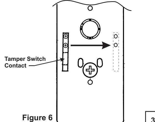
- Remove and relocate tamper switch contact from mounting base to opposite location as shown below (See Figure 6).
- 5. Reattach with (2) screws.

4. Standard Installation
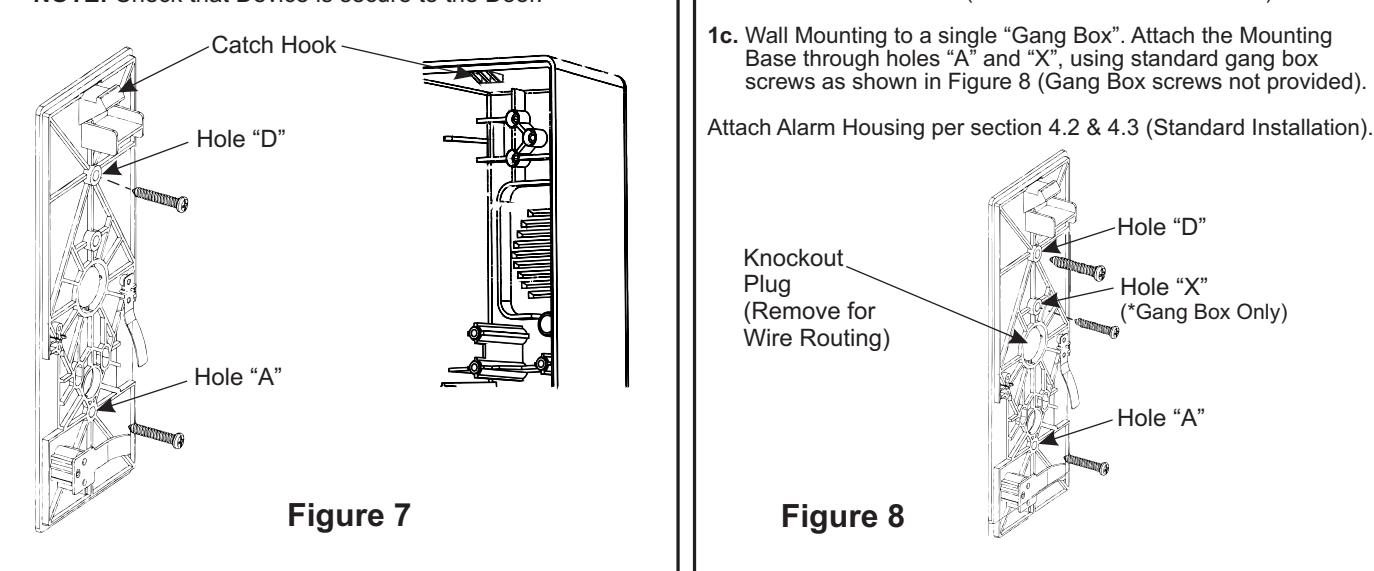
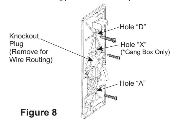
- 1. After preparing the door, attach the Mounting Base to door through holes "A" & "D", using (2) #10 screws provided, as shown below .
- 2. Attach Alarm Housing over hook at the upper end of mounting base. Pull downward and press towards the door, until housing is flush with surface of door.
- 3. Engage housing key into the bottom cylinder, underneath lower edge of housing. Rotate clockwise until positive latch is made.
NOTE: Check that Device is secure to the Door.
5. Hardwire Installation
Note: Hardwire options require wire harness within the door or wall and may require door position switches (DPS) or other means of activation. This unit is equipped to accept the Electrolynx™ quick connect system. See catalog for wiring harness and power supply details.
- 1a. Door Mounted. After preparing the door, remove Knockout Plug and attach the Mounting Base to the door through holes "A" & "D", using (2) #10 screws provided . NOTE: Knockout Plug will accept standard 1/2" electrical nipple to protect wires.
- 1b. Wall Mounting. This unit may be mounted between two doors, to monitor both doors (TIP: Attach unit to a wall stud).
- 1c. Wall Mounting to a single "Gang Box". Attach the Mounting Base through holes "A" and "X", using standard gang box screws as shown in Figure 8 (Gang Box screws not provided).
6. Standard Device x Outside Cylinder Control Installation
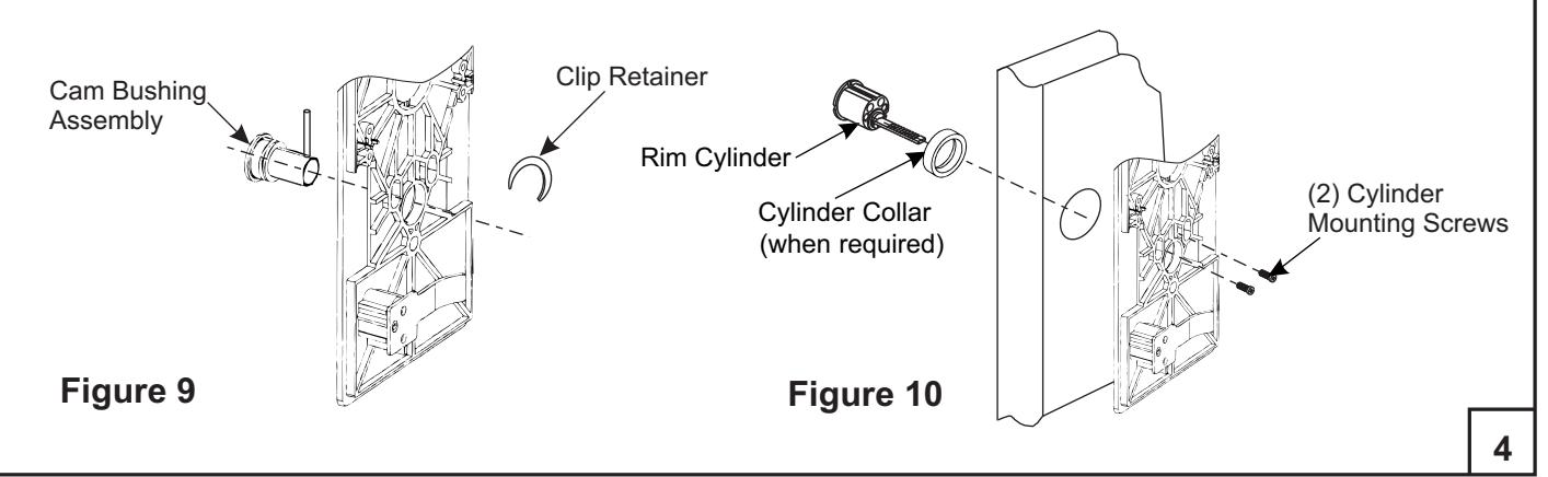
- 1. If not pre-assembled insert Cam Bushing Assembly through mounting base from the back side (See Figure 9) and install retainer clip onto exposed groove on bushing.
- 2 . Orient cam bushing assembly so that the long end of the pin is vertical (UP) in the 12 o'clock position.
- 3 . Attach mounting base to door, wall or Gang Box following previous instructions from Step 4 or 5.
- 4 . With mounting base securely attached to door, insert cylinder and ring through prep on opposite side of door, fasten securely with (2) cylinder screws inserted through slotted holes in the mounting base (See Figure 10).
NOTE: Cylinder Screws and Collar are supplied with the cylinder, when required.
ALARM FUNCTION AS SHIPPED
* The unit is shipped with power disconnected, attach battery connector as shown below.
- 1) Upon arming, LED will flash AMBER and the device will allow egress without triggering alarm for 7 seconds.
- 2) After 7 seconds, alarm will chirp one time and the device will be ARMED . The LED will flash RED every 30 seconds, indicating the device is ARMED .
- 3) Once the device is ARMED , egress will result in an alarm sound that will stop only when the device is RESET by key or remote.
- 4) Low Battery Indicator Alarm will chirp every 10 seconds, indicating battery needs to be replaced.
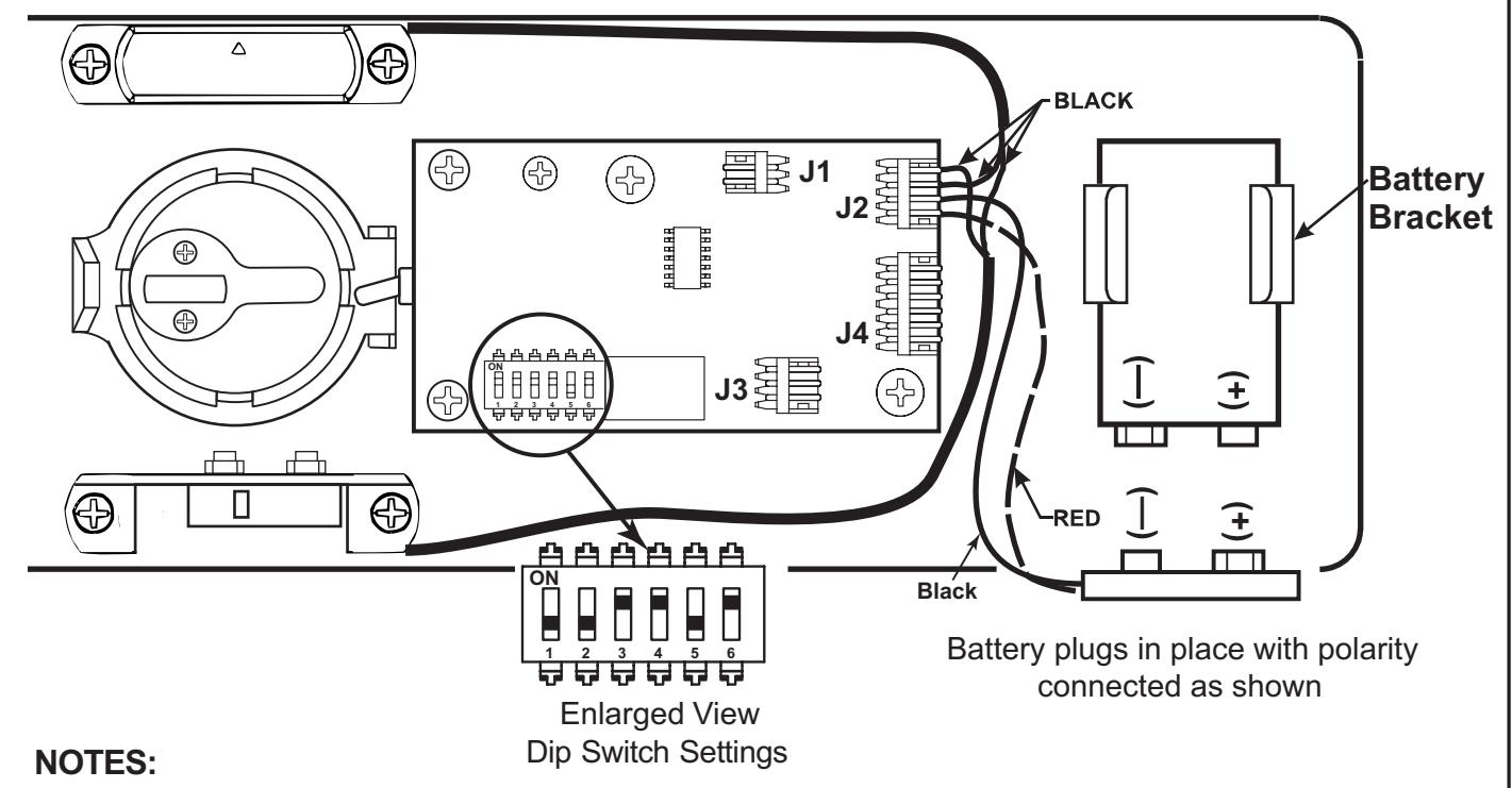
- Alarm PC Board has Dip Switches DS-1, 2, 3, 4, and 5 factory preset per Tables 1, 2, and 3 shown below.
- Dip Switch DS-6 is for "hard wire" configurations and setting does not affect stand-alone battery operation. When the unit is hard wired, DS-6 must be in the "On" position for remote monitoring thru connector J3.
| REX and Passage Time Delay When the device is initially ARMED by key, the LED will flash AMBER and allow egress for a time defined in Table 1. | TABLE 1 | ||
|---|---|---|---|
| DS-1 | DS-2 | Timer Delay | |
| *Off | *Off | 7 Seconds | |
| Off | On | 10 Seconds | |
| On | Off | 15 Seconds | |
| On | On | 20 Seconds | |
| Automatic Alarm Reset | TABLE 2 | ||
|---|---|---|---|
| The alarm can be set so that it will reset itself after a violation has occurred per Table 2. If the device automatically resets, the indicator light will flash GREEN every 30 seconds instead of RED to indicate a violation has occurred. | DS-3 | DS-4 | Reset Time |
| Off | Off | 2 Minutes | |
| Off | On | 5 Minutes | |
| On | Off | 10 Minutes | |
| *On | *On | No Auto Reset | |
| Armed and Violation LED Color Selection | TABLE 3 | |||
|---|---|---|---|---|
| Device is shipped standard, per Table 3, so that RED LED flashes every 30 seconds when device is ARMED , and flashes GREEN every 30 seconds under auto reset, when door has been violated. | DS-5 |
Armed
LED Color |
Armed Violation
LED Color |
Passage |
| *Off | Red | Green | Amber | |
| On | Green | Red | Amber | |
| *E | ||||
* Factory Preset
TROUBLESHOOTING
| Problem | Solution | |
|---|---|---|
|
Alarm will not sound
• |
•
Battery is not connected. Battery needs replacing. • • Alarm is not ARMED. Turn key clockwise. |
|
|
•
Alarm sounds when keyswitch is activated. |
Magnet Sensor is not installed correctly. Verify
• that the proper handing applies (See Step 3, Figure 5). |
|
|
•
Tamper Switch is not closing when Alarm Housing is installed. Make sure Switch Contact is located in the correct position (See Step 3, Figure 6). Verify that the Alarm Housing is installed correctly. |
||
|
•
J2 connector not installed, or loose. |
||
|
•
Alarm chirps every 10 seconds. |
•
Low battery indicator, replace battery. |
|
|
•
ARMED indicator LED, wrong color. |
•
Change position of DS-5 Dip Switch. "OFF" for RED ARMED indicator. "ON" for GREEN ARMED indicator. |
|
Product Support Tel 800.810.WIRE (9473) • www.yalelocks.com
Yale Locks & Hardware is a division of Yale Security Inc., an ASSA ABLOY Group company.
Yale® is a registered trademark of Yale Security Inc., an ASSA ABLOY Group company. Other products' brand names may be trademarks or registered trademarks of their respective owners and are mentioned for reference purposes only. These materials are protected under U.S. copyright laws. All contents current at time of publication. Yale Security Inc. reserves the right to change availability of any item in this catalog, its design, construction, and/or its materials. Copyright © Yale Security Inc., an ASSA ABLOY Group company. 2005, 2013
All rights reserved. Reproduction in whole or in part without the express written permission of Yale Security Inc. is prohibited.
6
CAUTION: Office copiers and facsimile machines may change the size of a drawing and make the template inaccurate to use as a door marker. If this is not the original template packed with the trim, use only the holes on the door (do not use template as a door marker).
Dimensions given in
| FUNCTION | HOLES |
|---|---|
| Standard Install | A, D, E |
| Hardwire Option | A, C, D, E |
|
Std. Install x
Outside Cylinder |
A, B, D, E |
* Hardwire Option Only
80-9470-0330-000 (01-13)
CAUTION: Office copiers and facsimile machines may change the size of a drawing and make the template inaccurate to use as a door marker. If this is not the original template packed with the trim, use only the holes on the door (do not use template as a door marker).
| FUNCTION | HOLES |
|---|---|
| Standard Install | A, D, E |
| Hardwire Option | A, C, D, E |
|
Std. Install x
Outside Cylinder |
A, B, D, E |
Dimensions given in
* Hardwire Option Only