ASSA ABLOY ACCENTRA SCP4020, 4420 Series, Holder, Stop Security Arm, Non-Hold Open & Hold Open_80-9344-0625-010
Open the original PDF document
View PDF

Installation Instructions
80-9344-0625-010 (06-09)
Holder-Stop Security Door Closer
Mr Habitat for Humanity
An incorrectly installed or improperly adjusted door closer can cause properly damage or personal injury. These instructions should be followed to avoid the possibility of misapplication or misadjustment.
Parallel Non Hold Open or Hold Open Arm
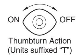
- For closers with or without "T" suffix Hold Open Control "T" indicates Thumbturn actuated hold open control.
- For closers with or without "DL" suffix (Delayed Action) closing feature.
| Series | Product Type | ||
|---|---|---|---|
|
Sized*
Closer |
Multi-Sized **
Closer |
Froduct Type | |
| SCP4020 | SCP4420 | Security Door Closer (Door Closer with both a Security Cover and Security Arm) 488 Drop Plate is available for doors with narrow top rails. | |
- * SCP4020 Series are sized door closers with 50% power increase capability. Power size 2 weakest power, power size 6 strongest.
- ** SCP4420 Series can be adjusted from power size 1 thru 6.
Note: For Special Applications a separate door and frame preparation template is packed with these instructions. Use this instruction sheet for installation sequence and closer adjustments only.
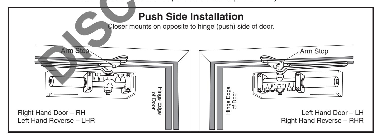
- Security Door Closers only. Door closer cover is handed and cannot be reversed. All other components are non handed.
- It is recommended that the door, on which the door closer will be installed, be hung on ball bearing hinges. Door must swing freely.
- A separate door stop, supplied by others, is recommended to prevent damage to the door closer, closer arm, or to the door, frame or adjacent walls.
- Door and Frame must be properly reinforced, or use of special fasteners employed, to prevent the mounting screws from pulling out.
- All dimensions are given in inches with corresponding metric dimensions (mm) in parenthesis.
- Torx tamper resistant drive screws are normally supplied with this product.
Template Page 2
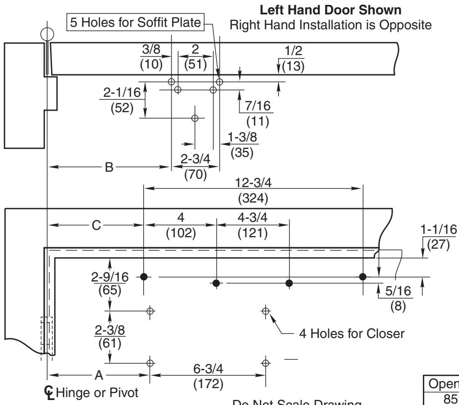

Do Not Scale Drawing Left Hand Door Shown Dimensions are in inches (mm). Maximum Door Swing 180°, conditions permitting.
|
2-3/4
(70) Min. |
- | |
|---|---|---|
| , | IVIIII. | |
| Soffit Plate | ||
| Arm Sto | op | • |
| , | Wide Stop F | rame |
| (70) | Min. | |
|
1-1/8
(29) Min. |
||
|
5/8
v(16) |
||
| √ 293S BI | ock | |
| Arm S | / / s | offit Plate |
Narrow Stop Frame
| Opening | Dim. A | Dim. B | Dim. C |
|---|---|---|---|
| 85° | 10-1/8 (257) | 10-5/8 (270) | 9-7/8 (251) |
| 90° | 9-1/4 (235) | 9-3/4 (248) | 9 (229.6) |
| 95° | 8-5/8 (219) | 9-1/8 (232) | 8-3/8 (213) |
| 100° | 7-7/8 (200) | 8-3/8 (213) | 7-5/8 (194) |
| 105° | 7-3/8 (187) | 7-7/8 (200) | 7-1/8 (181) |
| 110° | 6-3/4 (171) | 7-1/4 (184) | 6-1/2 (165) |
| Preparation for Fasteners | ||||||
|---|---|---|---|---|---|---|
| Fasteners | Door or Frame | Drill-Sizes | ||||
| Standard | Self Drilling Screw | Aluminum or Metal | No drill required | |||
| Wood | 3/16" (4.30 mm) | |||||
|
1/4" - 20
Machine Screw |
Metal |
Drill: #7 (0.201" dia.)
Tap: 1/4" - 20 |
||||
| Optional |
Sleeve Nuts and
Bolts (SNB) |
Hollow
Metal |
9/32" (7 mm); through 3/8" (9.5 mm) on door opposite to closer | |||
| Boils (SNB) | Aluminum or Wood | 3/8" (9.5 mm) through | ||||
| Through-bolts & grommet-nuts | All |
9/32" (7 mm); through
3/8" (9.5 mm) dia x 3/8" (9.5mm) deep on door opposite to closer |
||||
Installation Sequence
-
Use template above to locate holes on door and frame:
4 on door for closer or backplate.
- 5 on underside of frame stop for soffit plate.
- Prepare door and frame for fasteners using chart above.
• For SCP4420 Models Only
Set closer power for door size using chart below:
| Power Adjustment Chart | ||||
|---|---|---|---|---|
|
Door
Size |
Full Clockwise Turns of Closer Power Adjustment Nut | |||
| SCP4420 ONLY | ||||
|
inches
(mm) |
Interior
Door |
Exterior
Door |
||
|
28-32
(0.7 - 0.8) |
0 | 2 | ||
|
33-36
(0.85 - 0.9) |
2 | 5 | ||
|
37-42
(0.95 - 1.05) |
5 | 8 | ||
|
42-48
(1.1 - 1.2) |
8 | 11 | ||
| Closer is shipped set at median power setting. | ||||
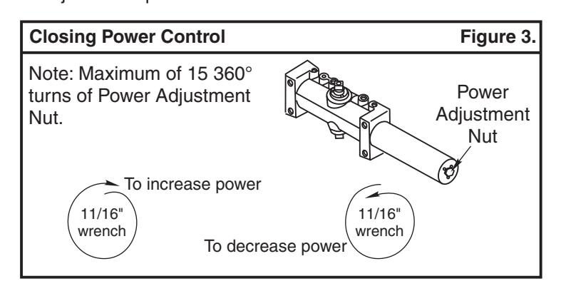
NOTE: Maximum of 15 360° turns of Power Adjustment Nut
crease 11/16" wrench or socket Power Adjustment Nut
Decrease
Installation Sequence (Con't) Page 3
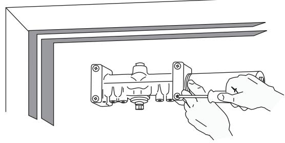
- Mount closer on door. Power Adjustment Nut DOWN Left Hand Door UP Right Hand Door (A drop plate is available for use on doors having narrow top rails) should be away from hinge. Valves are for . Valves are for .
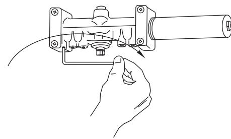
- Use 1/8" hex wrench to close valves. Turn Clockwise. For , close valves 'S/D' and 'L'. , close valves 'S' and 'L'. STANDARD CLOSER DELAYED ACTION CLOSER
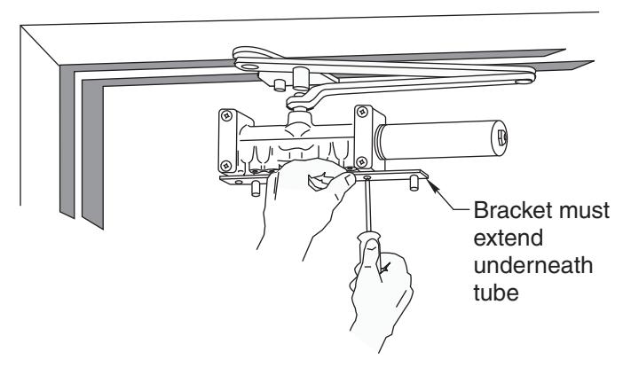
- - Set handing of "Arm Stop" on soffit plate. See illustration on Page 1 for positions. If required, rotate stop. Secure with 1/4-20 x 5/16 machine screw.
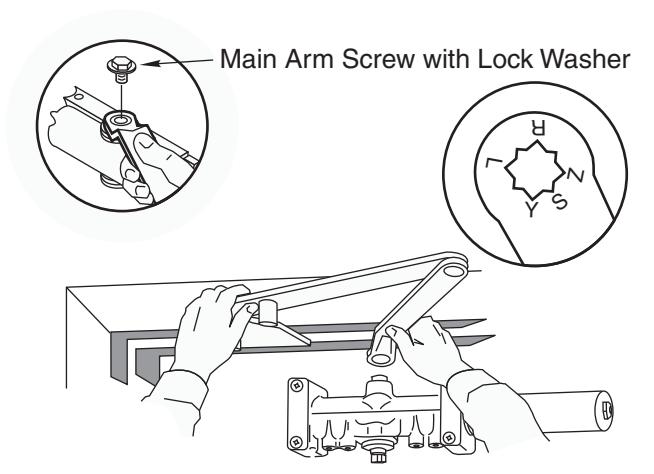
- With door closed, use wrench to rotate pinion shaft as illustrated below. -
Caution: Closer arm is under spring tension and may be difficult to rotate.
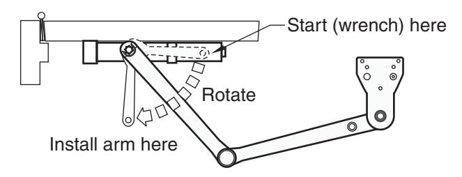
- Place main arm on shaft, aligning mark on arm with pinion flat on pinion shaft; "Z" for Left Hand Door; "Y" for Right Hand Door. Secure with 1/4-20 x 1/2 (13) round head machine screw with lock washer.
CAUTION! DO NOT BACK VALVES OUT OF CLOSER OR A LEAK WILL RESULT
- -Reopen valves closed in Step 2. Turn Counterclockwise
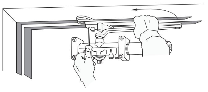
- -With door closed, align soffit plate with mounting holes in frame. Fasten soffit plate to frame with flat head screws provided.
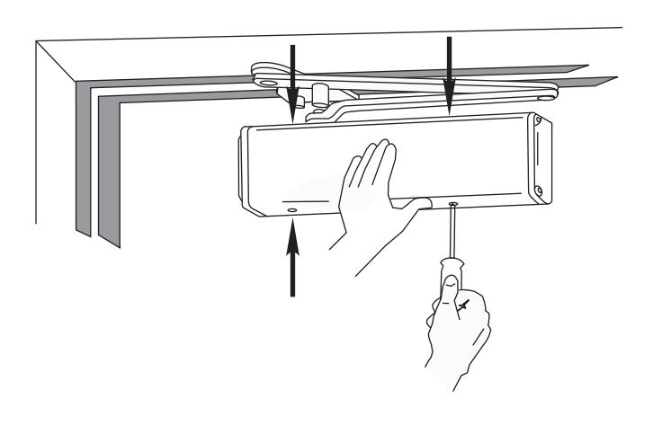
- Install Cover:
Security closers only, (SCP4420/SCP4020) Install cover bracket to closer body. (See Illustration below). Fasten bracket with 2 #8-32 x 5/16 RHMS screws provided.
Fasten cover to closer and cover bracket with 4 #8- 32x1/4 round head screws provided.
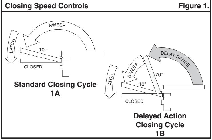
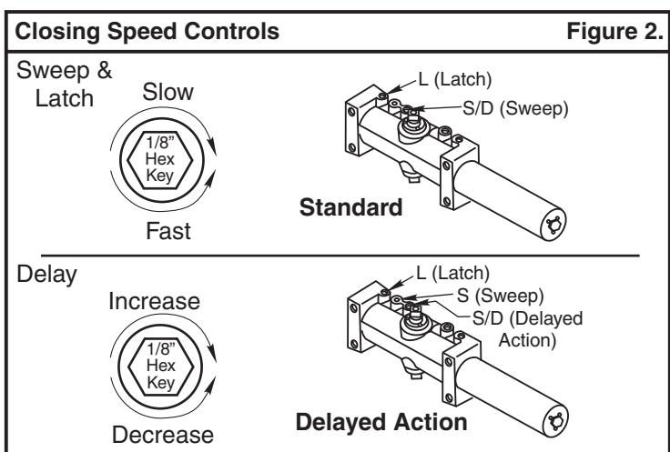
Closing Speed Controls (Figure 1A or 1B And 2.) Standard Closer Only
- Valve "S/D" Controls Sweep Range.
- Valve "L" Controls Latch Range.
Delayed Action Closer Only
- Valve "S/D" Controls Delay Range.
- Valve "S" Controls Sweep Range.
- Valve "L" Controls Latch Range.
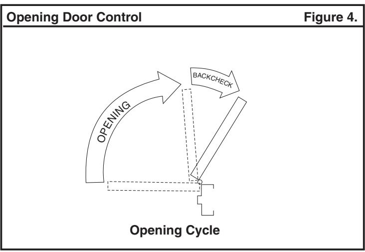
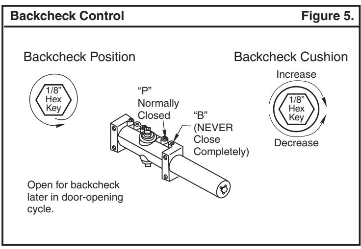
Opening Door Control (Figure 4.)
- Backcheck ("B") valve controls the hydraulic resistance to door opening. NEVER close this valve completely – it is not to provide a positive stop.
- •Backcheck position ("P") valve controls the door angle where backcheck cushioning starts. Valve normally closed.
Closing Power Adjustment (Figure 3.)
Adjust as required.
Door Holder Option
The Hold-Open feature is controlled by the knob located on the arm of the unit. A quarter turn of this knob engages or disengages the Hold-Open mechanism.