ASSA ABLOY ACCENTRA SC400, SC4400 Architectural Door Closers Catalog_42105
Open the original PDF document
View PDF
SC400/SC4400 Series
Security Door Closer


introduction
Yale's High Security Closers are designed for use in prisons, government buildings, schools, financial institutions, or any installation where vandalism, abuse, escape, personal injury, or damage to doors, walls, and hardware are major concerns.
The Security Closer Line uses Yale's 400 and 4400 series institutional door closers with a variety of regular rigid and parallel rigid arms and track options. Hold open arms are also available. Fixed link arm assemblies, permanent joints, orbital riveted elbows, arm shoe and soffit plate joints and Torx® screws with tread lock prevent disassembly. Torx screws with security pin are provided standard for tamper resistance. Yale's 400/4400 and 3000 series door closers are also offered with some of the same arm options as the SC400 or SC4400 but without the security cover. These closers are utilized in schools and industrial environments where heavy abuse and vandalism may occur.
Features:
- • Security arms joints feature permanent, orbital riveted elbow and arm shoe/ soffit plate joints which prevent disassembly
- • Adjustable backcheck cushioning and positioning
- • Torx drive machine screws with security pin
- Heavy-duty arms: Regular Rigid, Parallel Rigid, Holder/Stop and Holder/Stop Spring
- • 25-year limited warranty
Optional Features:
- • Slide track push or pull mounting
- • Delayed action
- • Enhanced backcheck
| contents | |
|---|---|
|
Introduction
|
2 |
| Compliance Standards |
3 |
|
How To Order
|
4-5 |
| Fasteners & Finishes | 6 |
|
Features
|
7-8 |
|
Specifications
|
9 |
| Applications | 10 |
|
Technical Details
|
11-16 |
| Accessories | 17-19 |
| Parts List | 20-25 |
| SCR4400, SCP4400 | SCR400, SCP400 | |
|---|---|---|
| Adjustable spring sizes 1 through 6 | X | — |
| Sized springs 2,3,4,5,6 with 50% power adjustment | — | X |

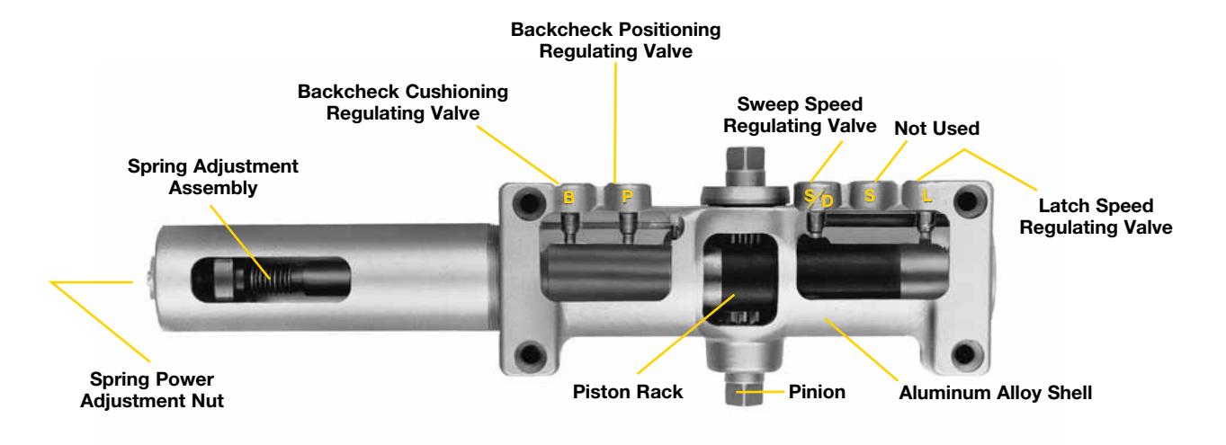
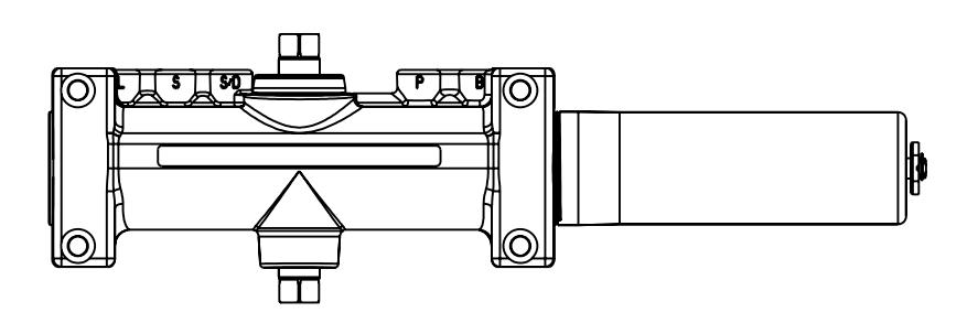
overview
Cutaway view (without delayed action)
compliance standards
All series SC400/SC4400 closers are ANSI/BHMA A156.4, Grade 1 certified. Closers with non-hold open arms are listed by Underwriters' Laboratories for labeled fire doors. This includes compliance to UL10C and for 3-hour assemblies. The series SC4400 door closers can be adjusted to comply with requirements of the Americans with Disabilities Act (A.D.A.) and ANSI standard A117.1. The product is manufactured in an ISO 9001 facility. These closers are also listed by the New York City Materials and Equipment Acceptance Division.
CAUTION: Door Closers for Low Opening Force Applications: Door closers installed in openings required to meet the requirements of The Americans with Disabilities Act or ANSI Standard A117.1, when adjusted to meet those requirements, may not provide adequate closing power to dependably close and latch the door.

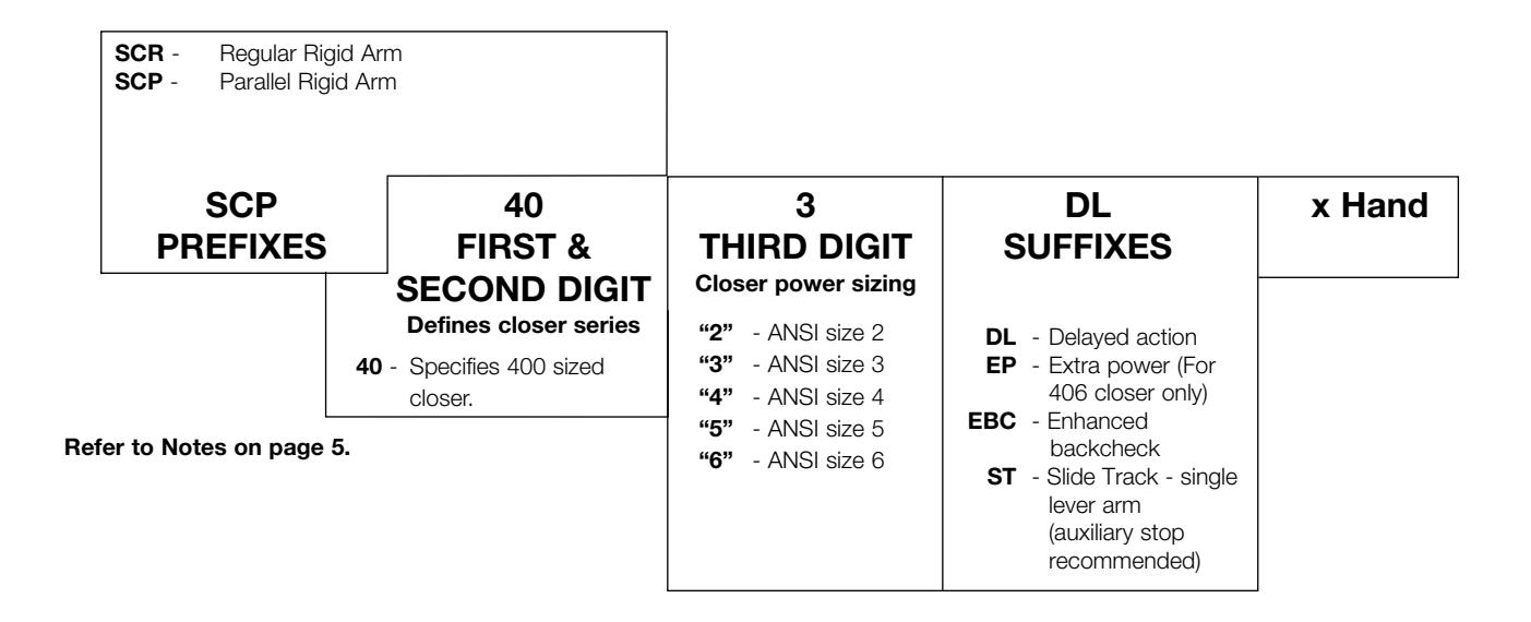
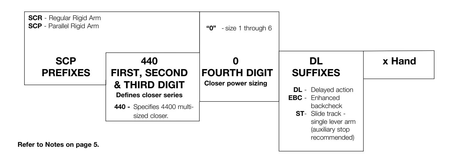
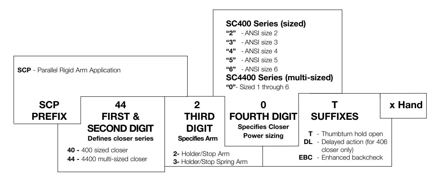
how to order
For optimum protection of door and frame assemblies, always use auxiliary wall, floor, or overhead door stop.
SCR400, SCP400 closer chart
SCR4400, SCP4400 closer chart

how to order
holder/stop and holder/stop spring arms
Notes:
- • Door closer warranty becomes void if it is installed on the exterior side of a door in the exterior wall of a building.
- • It is strongly recommended, and it is required on most fire door assemblies, that doors having a door closer be hung on ball-bearing or antifriction hinges or pivots.
- • Failure to use the correct type and size fasteners may void factory warranty.
- • Fasteners for fire/smoke door assemblies must conform to NFPA 80. In some applications additional fasteners may be mandated by NFPA 80 that are not shipped with Yale's standard product, such as sleeve-nuts/sex-nuts or through-bolts and grommet nuts.
- • The Torx® drive screws (with security pin), provided with the SC400/SC4400 door closers, are only available with machine screw threads.
- Contact factory if door weight exceeds 250 lbs.

fasteners and finishes
fasteners
- • Lobular Torx® drive screws for tamper resistance are standard with SCR400, SCP400, SCR4400, SCP4400 closers. These screws are only offered with machine threads for fastening to metal doors and frames. #14-10 wood or sheet metal fasteners, if required, must be supplied by others.
- • Parallel Rigid, Holder/Stop and Holder/Stop Spring arms are shipped standard with sleeve nuts (SN) and self-drilling screws.
finishes
Product will be painted with a combination of waterborne acrylic and polyester powder coat. Closers will withstand 100 hours of salt spray. ANSI requires 25 hours.
Sprayed Finishes
| Description |
Specify
(BHMA) Designation |
Complements the following
finishes |
Old Designation |
|---|---|---|---|
| Aluminum | 689 | 625, 628, 629, 630, 651, 652 | SB |
| Statuary Bronze | 690 | 613, 640 | STAT |
| Dull Bronze | 691 | 612, 637, 639 | BL |
| Black | 693 | 315 | 315 |
| Medium Amber | 694 | 312 | 312 |
| Gold | 696 | 605, 606, 632, 633 | GB |
| Prime Coat* | 600 | — | SRI |
* 600 is a special rust inhibiting prime coast. Closers can be ordered prime coat only (specify closer x 600). An additional charge applies if finish coat is required over prime coat (ex: SC4400 x 600 x 689).
Plated Finishes
| Description |
Specify (BHMA)
Designation |
Old Designation |
|---|---|---|
| Bright Brass | 605E | US3 |
| Satin Brass | 606E | US4 |
| Bright Bronze | 611E | US9 |
| Satin Bronze | 612E | US10 |
| Oxidized Oil Rubbed Bronze | 613E | US10B |
| Bright Chrome | 625E | US26 |
| Satin Chrome | 626E | US26D |
Finishes other than those listed above may be available on special order. A sample will be required.
When a plated finish is ordered, arm and cover will be plated unless "cover only" is specified.

features
Aluminum Alloy Housing
Closer bodies are constructed of a special aluminum alloy, carefully selected to accommodate interactive steel components and operating conditions.
Rack & Pinion Operation
Provides a smooth constant control of the door through its full opening and closing cycle. 180° door swing can be achieved when door, frame, hardware and arm function do not interfere.
Handed
All security closer covers are handed (closer cover must match hand of door).
Sweep Speed Control Valve
Allows adjustment of door speed from the door's full open position down to approximately 5° from the closed position.
Latch Speed Control Valve
Allows adjustment of door speed from approximately 5° down to the door's fully closed position.
Non-Critical Control Valves
All control valves for sweep speed, latch speed and backcheck cushioning are non-critical and are adjusted by a standard 1/8" (3mm) hex wrench.
Adjustable Backcheck Cushion Valve
Provides control of the door in the opening cycle, beginning at approximately 75° of door opening. It cushions the door opening when the door is forcibly opened beyond its pre-adjusted limits.
Adjustable Backcheck Position Valve
Allows the door opening position, where backcheck cushioning begins, to be adjusted to a greater door angle, up to a maximum of 20° farther (approximately 95°).
Security Cover
Supplied standard with all series SC400/SC4400 door closers. This deep drawn steel cover is handed for all applications. The cover is fastened to the closer body at four points; two at the top and two at the bottom.
Warranty
These closers carry a limited twentyfive year warranty against defect, and life of the building on the aluminum housing.
Closer Fluid
Specially formulated multi-viscosity hydraulic fluid contains lubricity and anti-oxidation agents that provide optimum performance and efficiency. This fluid complements the interaction of the door closer's aluminum housing with its steel and brass components, while maintaining stable viscosity to allow the door closer to perform in temperatures ranging from extremely high to as low as -40° F.
Door Closer Power Options Series SCR/SCP400 Sized Door Closer
Available in five different power sizes (2, 3, 4, 5 or 6). Each power size is adjustable up to 50% stronger than the minimum closing force for that size, as outlined in ANSI/BHMA standard A156.4.
Series SCR/SCP4400 Multi-Sized Door Closer
Adjustable through the entire power range of door closer sizes 1 through 6, as outlined in ANSI/BHMA standard A156.4.
The series SCR/SCP4400 also conforms to the minimum opening force requirements of the Americans with Disabilities Act (A.D.A.) and ANSI/BHMA standard A117.1 for interior doors.

optional features
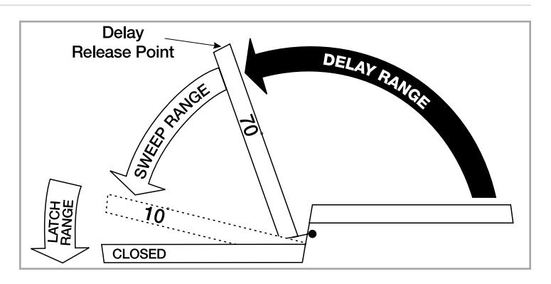
delayed action
Adjustable Delayed Action Closing
An optional hydraulic feature that adds a third speed range to the closing cycle. This feature becomes effective when the door is opened and released at any point beyond 70°. The amount of time delay depends upon the combination of the angle of door release and valve adjustment. The valve can be adjusted with a 1/8" (3mm) hex key from no delay time up to maximum delay times of:
|
Door Opened and
Released at |
Approximate Time
of Delay Cycle |
|---|---|
| 180° | 4-5 minutes |
| 120° | 2-3 minutes |
| 120° | 25-30 seconds |
Pressure Relief Safety Valve
The delayed action hydraulic system contains a pressure relief valve. Any time the door is forced toward the closed direction while it is in the closing cycle, the valve will open and permit the door to close. This prevents damage to door, frame and closer.
Suggested Applications
Delayed Action closing allows slow-moving traffic to clear the opening before the door closer's normal closing cycle begins. This feature can be helpful in health care facilities such as hospitals and nursing homes. It provides sufficient time for persons on crutches or in wheelchairs to pass through a door without concern of it closing. At the same time, it can accommodate the facility's staff with movement of food service carts, beds, and other wheeled traffic.
Use of delayed action closers on many doors throughout industrial and commercial buildings can also assist the flow of traffic. Locations where additional time to clear the opening is advantageous are doors between office and factory/warehouse facilities, doors to workshops or laboratories, to kitchen and food processing areas.
arms
Non-Hold Open
Self-closes door every time door is opened. Auxiliary stop (by others) required except when using the Holder/Stop or Holder/Stop Spring arms.
Hold Open
Achieved by means of ball and detent/roller. Ball and detent or roller hold open is effective in a range of 85° to 110°.
Hold open arm door closers are not permitted to be used on fire door assemblies.
| Arm Function | Regular Rigid Arm | Parallel Rigid Arm | Holder/Stop Arm |
Holder/ Stop
Spring Arm |
|---|---|---|---|---|
| Non-Hold Open | 3 | 3 | 85˚ to 110˚ | 85˚ to 110˚ |
| Hold Open | — | — | 85˚ to 110˚ | 85˚ to 110˚ |
3 = 180° trim and template permitting

suggested specifications
SC4400 Series
Closers for interior and exterior doors shall be full rack-and-pinion type with cast aluminum alloy body. Closers shall be surface mounted and shall project no more that 2-3/16" (56mm) from the surface of the door. Closers shall be reversible but supplied with a handed metal cover. Closer fluid shall contain lubricity and anti-oxidation agents. Closer fluid shall maintain stable viscosity to allow door closer to perform in temperatures ranging from extremely high to as low as -40°F. Closers shall have multi-size spring power adjustment to permit setting of spring from size 1 through size 6. Closers shall have two non-critical valves, hex key adjusted, to independently regulate sweep and latch speed. Closers shall have backcheck cushioning beginning at 15° of door opening controlled by a hex key adjustable valve. (Closers shall have backcheck position controlled by a hex key adjustable valve.)
[Closers shall have adjustable delayedaction closing controlled by a hex key adjustable valve.]
**Closers shall be enclosed in a [plated] [sprayed] metal cover. Closers to be Yale® [SCR4400, SCP4400]. Covers shall be fastened to the body at four points, two at the top and two at the bottom to prevent prying.
**For special arms insert the appropriate specification from column three on this page.
SC400 Series
Closers for interior and exterior doors shall be full rack-and-pinion type with cast aluminum alloy shell. Closers shall be surface mounted and shall project no more that 2-3/16" (56mm) from the surface of the door. Closers shall be reversible but supplied with a handed metal cover. Closer fluid shall contain lubricity and anti-oxidation agents. Closer fluid shall maintain stable viscosity to allow door closer to perform in temperatures ranging from extremely high to as low as -40°F. Closers shall have power adjustment to permit a 50% increase in power over the minimum closing force for each size. Closers shall have two non-critical valves, hex key adjusted, to independently regulate sweep and latch speed. Closers shall have backcheck cushioning beginning at 15° of door opening controlled by a hex key adjustable valve. (Closers shall have backcheck position controlled by a hex key adjustable valve.)
[Closers shall have adjustable delayed action closing controlled by a hex key adjustable valve.]
**Closers shall be enclosed in a [plated] [sprayed] metal cover. Closers to be Yale [SCR400, SCP400]. Covers shall be fastened to the body at four points, two at the top and two at the bottom to prevent prying.
**For special arms insert that specification here (see column three on this page).
**Holder/Stop Arm
Door closers shall have built-in door stop [and holder] effective at one point selected at installation, from 85° - 110° in five-degree increments. Door stop mechanism shall be reversible and attached to soffit plate. [Hold open mechanism shall have engage/disengage selection actuated by thumbturn.] Closers shall be provided for parallel arm installation using rigid steel main and secondary arms (SCP4020)(T), (SCP4420)(T).
**Holder/Stop Spring Arm
Door closers shall have built-in door stop [and holder] effective at one point selected at installation, from 85° - 110° in five-degree increments. Door stop mechanism shall have a buffer spring that engages prior to the dead stop feature, reducing shock loads to the door and frame assembly. Door stop mechanism shall be reversible and attached to soffit plate. [Hold open mechanism shall have engage/disengage selection actuated by thumbturn.] Closers shall be provided for parallel installation using rigid steel main and secondary arms (SCP4030)(T), (SCP4430)(T).

applications
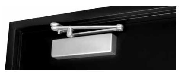
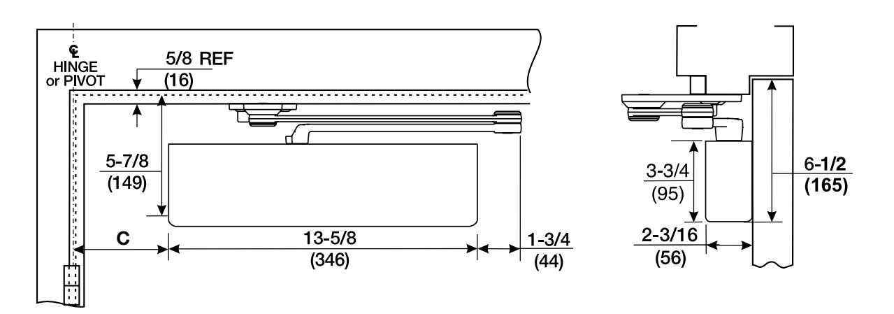
regular rigid arm
This double lever arm features a non-adjustable secondary arm. Orbitally riveted joints prevent tampering or disassembly. The rigid heavy-duty arm is standard with the security closers featuring a regular arm application.
Auxilary door stop required. Available non-hold open only.
SCR400/SCR4400
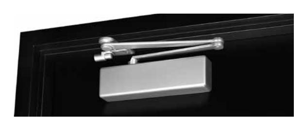
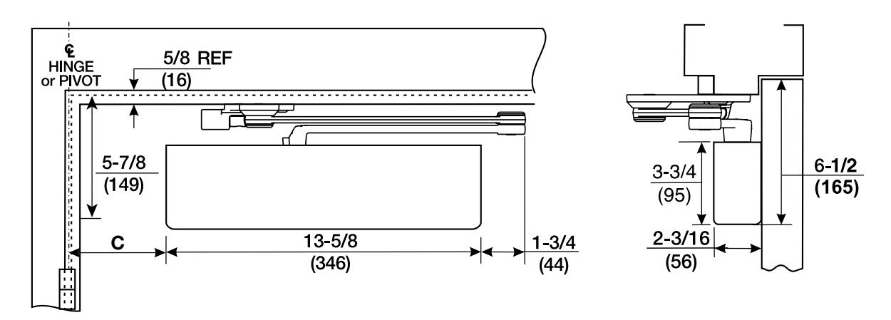
parallel rigid arm
An enhanced variation of the standard parallel arm assembly that is intended for use in heavy traffic areas where auxiliary door stops are installed.
Auxilary door stop required. Non-hold open only.
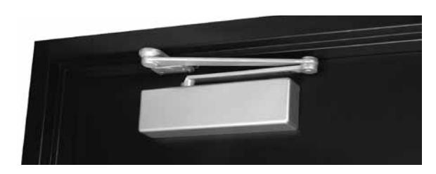
SCP400/SCP4400
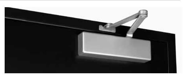
holder/stop arm
Similar to the Parallel Rigid arm, this arm incorporates a stop at the arm's soffit plate to dead stop the door at a predetermined degree of door swing between 85° and 110°, in 5° increments. Prior to dead stop the door closer's backcheck feature slows the door speed to reduce the impact of the stop action.
Holder/Stop arm is intended for use where an auxiliary door stop cannot be utilized and no more than moderate abuse is anticipated.
SCP4020T/SCP4440T
Thumbturn hold open available. (Hold open strength is adjustable.)
holder/stop spring
This heavy-duty stop arm includes all of the features of the Holder/Stop Arm, plus an added buffer spring that is compressed prior to the arm hitting the dead stop point. This greatly reduces the shock of the stopping action that occurs with the Holder/Stop arm.
Holder/Stop Spring Arm is intended for use where an auxiliary door stop cannot be utilized and no more than moderate abuse is anticipated.
Thumbturn hold open available. (Hold open strength is adjustable.)
SCP4030T/SCP4430T

regular rigid arm
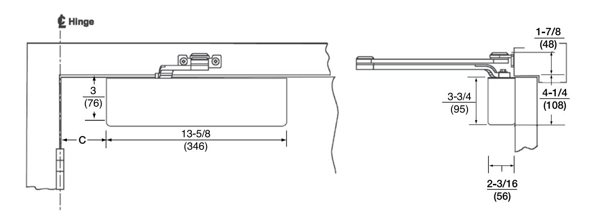
Mounting holes for closer body are spaced 2-3/8" (60mm) vertically x 6-3/4" (171mm) horizontally.
|
C
Template Position |
||||
|---|---|---|---|---|
| 0° to 100° | 101° to 120° 121° to 150° 151° to 180° | |||
|
6-3/8"
(162mm) |
5-3/8"
(137mm) |
3-3/8"
(86mm) |
3-1/8"
(79mm) |
|
| Maximum Door Width | Model Number | ||
|---|---|---|---|
| Inches (cm) | Sized Closers | Multi-Sized Closers | |
| Interior | Exterior | Non-Hold Open | |
| 36" (91) | 30" (76) | SCR402 | |
| 42" (107) | 36" (91) | SCR403 | |
| 46" (117) | 42" (107) | SCR404 | SCR4400 |
| 54" (137) | 48" (122) | SCR405 | |
| — | 52" (132) | SCR406 |
Note: SC4400 door closers are set at midpower range from the factory and can be adjusted for door sizes noted above.
Sizing charts are based on 1-3/4" (44mm) x 7'0" (2.13m) standard weight doors swinging to 110°. Other conditions (such as door height or weight, or wind/draft conditions) may require a larger size closer.

parallel rigid arm
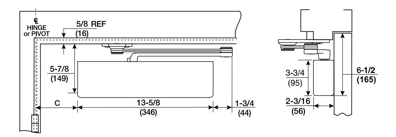
Mounting holes for closer body are spaced 2-3/8" (60mm) vertically x 6-3/4" (171mm) horizontally.
|
C
Template Position |
||
|---|---|---|
| 0° to 100° | 101° to 120° | 121° to 180° |
|
8-1/8"
(206) |
7-1/8"
(181) |
6-1/8"
(156) |
| Maximum Door Width | Model Number | |||
|---|---|---|---|---|
| Inches (cm) | Sized Closers | Multi-Sized Closers | ||
| Interior | Exterior | Non-Hold Open | ||
| 30" (76) | — | SCP402 | ||
| 36" (91) | 32" (81) | SCP403 | SCP4400 | |
| 42" (107) | 36" (91) | SCP404 | ||
| 48" (122) | 42" (107) | SCP405 | ||
| — | 48" (122) | SCP406 | ||
Note: SC4400 door closers are set at midpower range from the factory and can be adjusted for door sizes noted above.
Sizing charts are based on 1-3/4" (44mm) x 7'0" (2.13m) standard weight doors swinging to 110°. Other conditions (such as door height or weight, or wind/draft conditions) may require a larger size closer.

holder/stop arm
Mounting holes for closer body are spaced 2-3/8" (60mm) vertically x 6-3/4" (171mm) horizontally.
|
C
Template Position for Hold Open or Stop at Listed Angle (mm) |
|||||
|---|---|---|---|---|---|
| 85° | 90° | 95° | 100° | 105° | 110° |
|
9-5/8
(244) |
8-3/4
(222) |
8-1/4
(210) |
7-3/8
(187) |
6-7/8
(175) |
6-1/4
(159) |
| Maximum Door Width | Model Number | ||||
|---|---|---|---|---|---|
| Inches (cm) |
Sized Closers
Multi-Sized Closers |
||||
| Interior | Exterior | Non-Hold Open | Hold Open | Non-Hold Open | Hold Open |
| 30" (76) | — | SCP4022 | SCP4022T | ||
| 36" (91) | 32" (81) | SCP4023 | SCP4023T | ||
| 42" (107) | 36" (91) | SCP4024 | SCP4024T | SCP4420 | SCP4420T |
| 48" (122) | 42" (107) | SCP4025 | SCP4025T | ||
| — | 48" (122) | SCP4026 | SCP4026T | ||
Note: SC4400 door closers are set at midpower range from the factory and can be adjusted for door sizes noted above.
Sizing charts are based on 1-3/4" (44mm) x 7'0" (2.13m) standard weight doors swinging to 110°. Other conditions (such as door height or weight, or wind/draft conditions) may require a larger size closer.

holder/stop spring
Mounting holes for closer body are spaced 2-3/8" (60mm) vertically x 6-3/4" (171mm) horizontally.
|
C
Template Position for Hold Open or Stop at Listed Angle (mm) |
||||||||
|---|---|---|---|---|---|---|---|---|
| 85° | 90° | 95° | 100° | 105° | 110° | |||
|
9-5/8
(244) |
9-5/8 8-3/4 8-1/4 7-3/8 6-7/8 6-1/4 (244) (222) (210) (187) (175) (159) | |||||||
| Maximum | Door Width | Model Number | |||
|---|---|---|---|---|---|
|
Maximum Door Width
Inches (cm) |
Sized C | Sized Closers Multi-Sized Closers | |||
| Interior Exterior | Non-Hold Open |
Thumbturn
Hold Open |
Non-Hold Open |
Thumbturn
Hold Open |
|
| 30" (76) | _ | SCP4032 | SCP4032T | ||
| 36" (91) | 32" (81) | SCP4033 | SCP4033T | ||
| 12" (107) | 36" (91) | SCP4034 | SCP4034T | SCP4430 | SCP4430T |
| 18" (122) | 42" (107) | SCP4035 | SCP4035T | ||
| _ | 48" (122) | SCP4036 | SCP4036T | ||
Note: SC4400 door closers are set at midpower range from the factory and can be adjusted for door sizes noted above.
Sizing charts are based on 1-3/4" (44mm) x 7'0" (2.13m) standard weight doors swinging to 110°. Other conditions (such as door height or weight, or wind/draft conditions) may require a larger size closer.

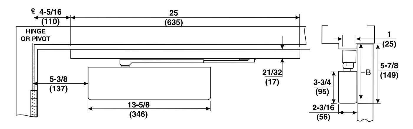
pull side slide track
Mounting holes for closer body are spaced 2-3/8" (60mm) vertically x 6-3/4" (171mm) horizontally.
|
B
Minimum Top Rail of Door with Frame Stop |
|
|---|---|
| Without Drop Plate |
With 486
Drop Plate |
| 3-1/2" (89mm) | 2" (51mm) |
| Maximum Door Width | Model Number | |
|---|---|---|
| Inches (cm) | Sized Closers | Multi-Sized Closers |
| Interior | Non-Hold Open | |
|
32"
(81) |
SCR404ST | |
|
38"
(97) |
SCR405ST | SCR4400ST |
|
48"
(122) |
SCR406ST | |
Note: SC4400 door closers are set at midpower range from the factory and can be adjusted for door sizes noted above.
Door will swing up to 110° with buffer. Without buffer, door will swing to 180°. Auxiliary stop required for all applications.

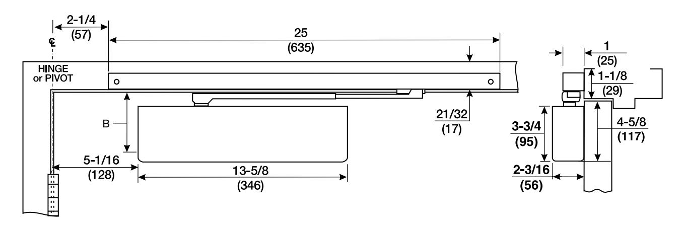
push side slide track
Mounting holes for closer body are spaced 2-3/8" (60mm) vertically x 6-3/4" (171mm) horizontally.
|
B
Minimum Top Rail of Door with Frame Stop |
||
|---|---|---|
| Without Drop Plate | With 488 Drop Plate | |
| 5-1/4" (133mm) | 3-5/8" (92mm) | |
| Maximum Door Width | Model Number | |
|---|---|---|
| Inches (cm) | Sized Closers | Multi-Sized Closers |
| Interior | Non-Hold Open | |
|
32"
(81) |
SCP404ST | |
|
38"
(97) |
SCP405ST | SCP4400ST |
|
48"
(122) |
SCP406ST | |
Note: SC4400 door closers can be adjusted for door sizes noted. Multi-size closers are set at mid power range from the factory. Maximum degree of door swing is 125°. Auxiliary stop required for all applications.

accessories
regular rigid arm closer mounting plate (all parallel arm applications)
Narrow Top Rail - #486 Drop Plate: For use where the narrow top rail of the door prevents the closer from being mounted directly to the door surface. This drop plate must be used for a closer mounted on a top rail between 1-7/8" and 3-3/8" (48 and 86mm) in height.
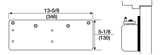
parallel rigid arm closer mounting plate
Narrow Top Rail - #488 Drop Plate: For use where a narrow top rail prevents the closer from being mounted directly to the door surface. This drop plate can be used to mount a closer on a top rail as narrow as 2-1/2" (64mm) in height.

parallel rigid arm brackets
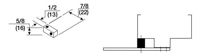
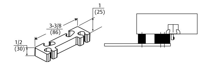
Standard - #293S Spacer Block: For use where a narrow frame soffit does not provide adequate support for the soffit plate. Supplied as standard with all parallel rigid arm closers.

accessories
parallel rigid arm brackets
Parallel Arm - #293L Drop Plate: For use where a narrow top rail prevents the closer from being mounted directly to the door surface. This drop plate can be used to mount a closer on a top rail as narrow as 2-5/8" (57mm).
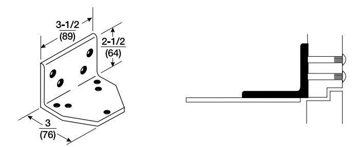
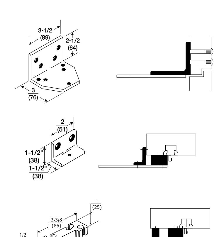
Narrow Frame - #890 Support Bracket: For use where the frame is narrow, and the soffit plate cannot be mounted directly to the frame soffit or rabbet. Used in combination with the #891 Spacer Block on blade stop frames to provide extra support and needed clearance of the blade stop.
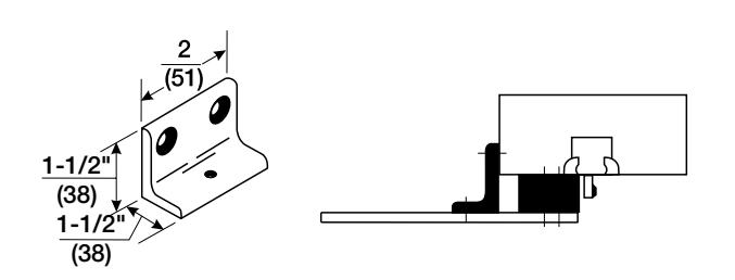
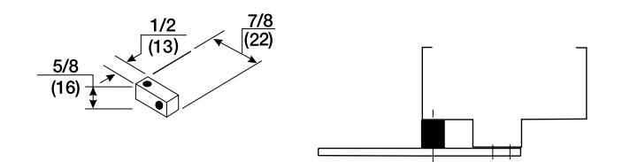
Clearance/Support Blade Stop - #891 Spacer
Block: For use where the door frame has a blade stop and the soffit plate must be mounted on the frame rabbet. This accessory is used in combination with the standard spacer block to provide clearance of the blade stop.
holder/stop and holder/stop spring arm mounting plates
Narrow Top Rail - #488 Drop Plate: For use where a narrow top rail prevents the closer from being mounted directly to the door surface. This drop plate can be used to mount a closer on a top rail as narrow as 2-1/2" (64mm) in height.

accessories
brackets (non-hold open & hold open arms)
Standard - #293S Spacer Block: For use where a narrow frame soffit does not provide adequate support for the soffit plate. Supplied as standard with all parallel rigid arm closers.
Flush Rabbeted Transom - #293L Angle
Bracket: For use where flush transom conditions prevent mounting of the standard soffit plate. This bracket is used in combination with the standard soffit plate.
Narrow Frame - #890 Support Bracket: For use where the frame is narrow, and the soffit plate cannot be mounted directly to the frame soffit or rabbet. Used in combination with the #891 Spacer Block on blade stop frames to provide extra support and needed clearance of the blade stop.
Clearance/Support Blade Stop - #891 Spacer Block: For use where the door frame has a blade stop and the soffit plate must be mounted on the frame rabbet. This accessory is used in combination with the standard spacer block to provide clearance
of the blade stop.
(89mm) 5/8"
(16mm)

closer body assemblies
| Torx® Screw Pack* | ||
|---|---|---|
| Arm Type |
Part
Number |
|
|
Regular Rigid
Heavy-Duty |
RTX47 | |
|
Parallel Rigid,
Holder/Stop and Holder/Stop Spring |
PRTX47 | |
| Closer Bodies | ||
|---|---|---|
|
Part
Description Number |
||
| 4400LAP | Multi-Size Closer Body | |
| 4400DLLAP | With Delayed Action | |
| 40*LAP | Sized Closer Body | |
| 40*DLLAP | With Delayed Action | |
* Specify power size 2, 3, 4, 5 or 6 when ordering
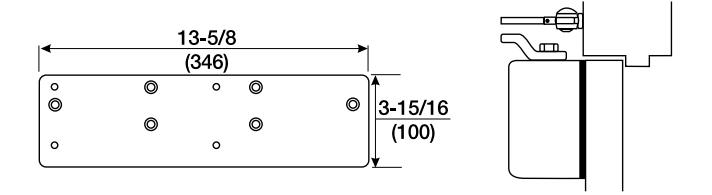
| Covers | ||||
|---|---|---|---|---|
| Part Number | Mounting | Handing | Dimensions | Material |
| SC400CRR | Right Hand | |||
| SC400CRL | Regular Arm | Left Hand | Length: 13-5/8" (346mm) | |
| SC400CPR | Right Hand |
Width: 3-3/4" (95mm)
Projection: 2-3/16" (56mm) |
Metal | |
| SC400CPL | Parallel Arm | Left Hand | ||
* Torx® screws with machine screw threads are supplied with security closers.
LAP = Less All Parts

regular rigid arm assembly
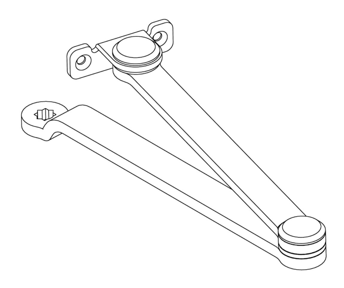
| Arm Function | Complete Arm Package |
|---|---|
| Non-Hold Open | 470-1 |

parallel rigid arm assemblies
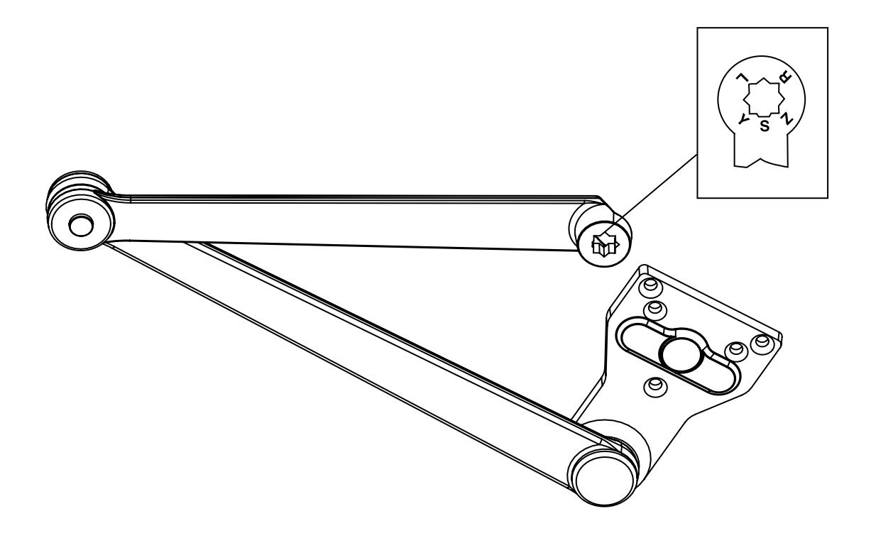
| Arm Function | Complete Arm Assembly |
|---|---|
| Non-Hold Open | 470-5 |

holder/stop arm assemblies
Hold Open Arm Shown
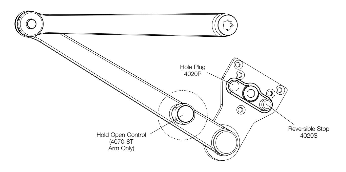
| Arm Function | Complete Arm Package |
|---|---|
| Non-Hold Open | 4070-5 |
| Thumbturn Hold Open | 4070-8T |

holder/stop spring arm assemblies
Non-Hold Open Arm Shown
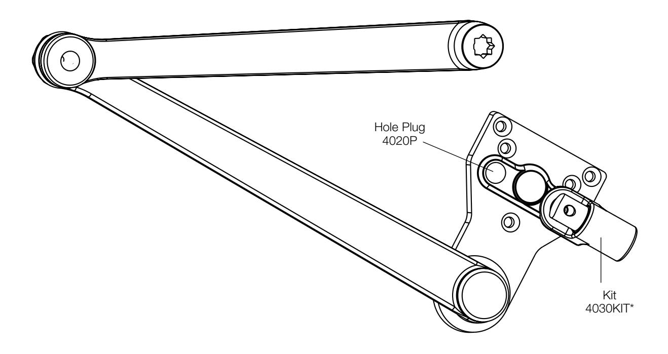
| Arm Function | Complete Arm Package |
|---|---|
| Non-Hold Open | SC4070-5 |
| Thumbturn Hold Open | SC4070-8T |
* 4030 KIT can be used to upgrade 4070-5 or 4070-8T arms.

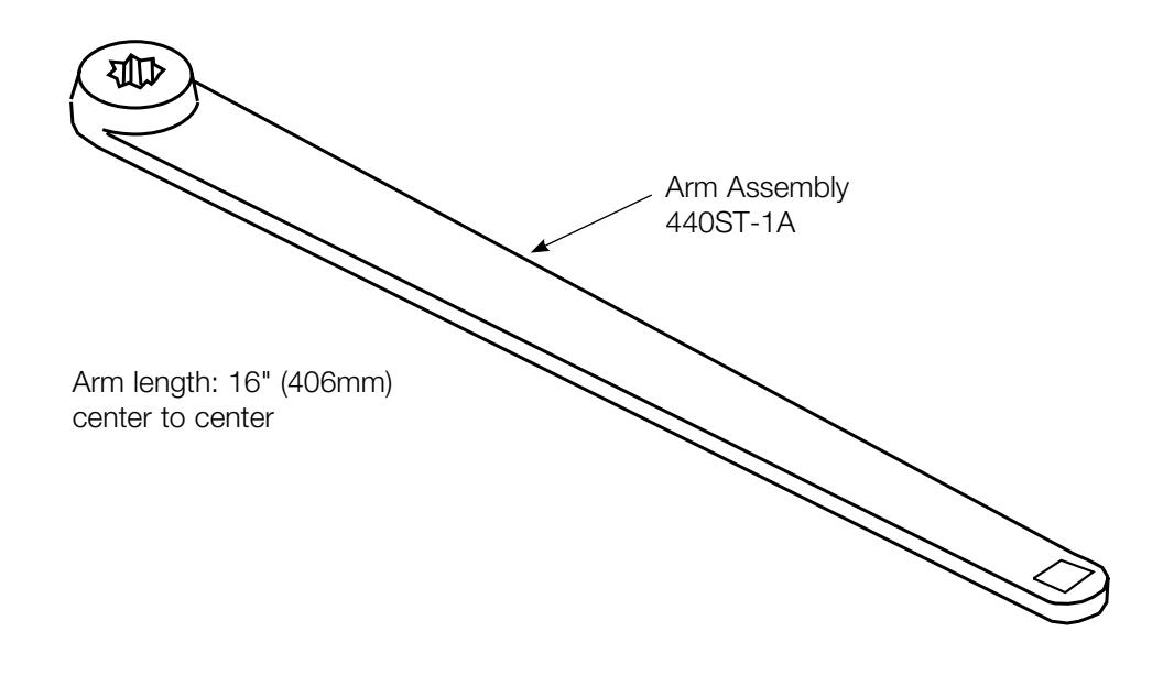
track assemblies
| Non-Hold Open | |
|---|---|
| Model | Slide Track Assembly |
| Pull-side mounted | 440ST-1T |
| Push-side mounted | 440ST-5T |
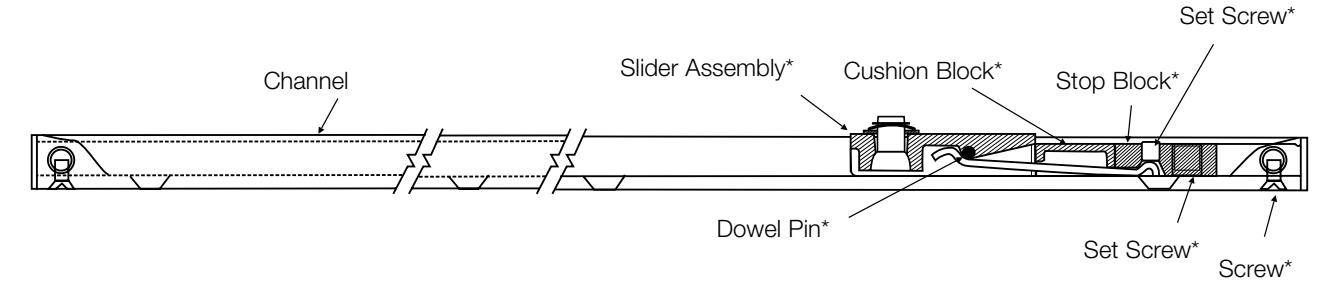
*Part of an Assembly Pack Non-Hold Open = 400SLD

online literature and templates
For the latest information on Yale Locks & Hardware products, visit our website at: www.yalelocks.com
Click on the "Product Information" button to find:
- • Catalogs
- • Parts manuals
- • Templates
- • Specifications
- • Installation instructions
Yale® customers can click on the ebusiness symbol on the website to register for an ebusiness account to:
- • Check the status of orders
- • Check availability of QuickShip items
- • Track your order and confirm delivery
- • Receive email notification of template changes And More...
Or contact us at:
U.S.A.
Yale Locks & Hardware
Address: 225 Episcopal Road, Berlin, CT 06037-4004 Tel: 1-800-438-1951 • Fax: 1-800-338-0965 • www.yalelocks.com
Canada:
ASSA ABLOY Door Security Solutions Canada
Address: 160 Four Valley Drive, Vaughan, Ontario L4K 4T9 Tel: 1-800-461-3007 • Fax: 1-800-461-8989 • www.assaabloy.ca
International:
ASSA ABLOY Americas International
Tel: 1-905-821-7775 • Fax: 1-905-821-1429 • www.assaabloyai.com
Yale Locks & Hardware is a division of Yale Security Inc., an ASSA ABLOY Group company.
Yale® is a registered trademark of Yale Security Inc., an ASSA ABLOY Group company. Other products' brand names may be trademarks or registered trademarks of their respective owners and are mentioned for reference purposes only. These materials are protected under U.S. copyright laws. All contents current at time of publication. Yale Security Inc. reserves the right to change availability of any item in this catalog, its design, construction, and/or its materials. Copyright © 2001, 2012, Yale Security Inc., an ASSA ABLOY Group company. All rights reserved. Reproduction in whole or in part without the express written permission of the Yale Security Inc., an ASSA ABLOY Group company. is prohibited.
YALE , with its unique global reach and range of products, is the world's favorite lock.
ASSA ABLOY is the global leader in door opening solutions, dedicated to satisfying end-user needs for security, safety and convenience.
42105-9/12R