ASSA ABLOY ACCENTRA RL Series Tubular Locks Installation Instructions_80-9510-0070-000
Open the original PDF document
View PDFRL Series
Tubular Lock
Installation Instructions
1. Tools Required
y #2 Phillips screwdriver
y 1/8" drill bit
y 1" drill bit
y 3/32" Hex Wrench
y 2-1/8" drill bit
y Right angle square (square roses)
2. Product Components
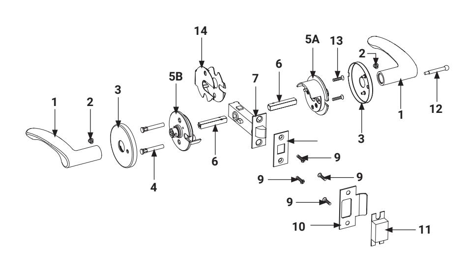
| Item | Description | Qty |
|---|---|---|
| 1 | Lever | 2 |
| 2 | Set Screw | 2 |
| 3 | Rose Assembly | 2 |
| 4 | Mounting Post | 2 |
| 5A | Inside Spring Housing | 1 |
| 5B | Outside Spring Housing | 1 |
| 6 | Spindles | 2 |
| 7 | Latch | 1 |
| 8 | Faceplate | 1 |
| 9 | Screws - Latch & Strike #8-32 x 3/4" | 4 |
| 10 | Strike | 1 |
| 11 | Strike Box | 1 |
| 12 | Push Button (RL202 Only) | 1 |
| 13 | Mounting Post Screw | 2 |
| 14 | Fire Guard Clip (Fire Rated option only) | 1 |
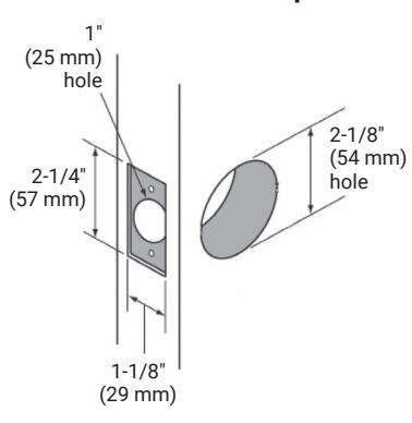
3. Door and Frame Preparation
- y Hollow Metal Doors should be properly reinforced for lock support. If support is not provided, contact door manufacturer.
- y Refer to Template 7150-0100 or 7150-0101 for door preparations. Use Door Marker supplied and information below for reference.
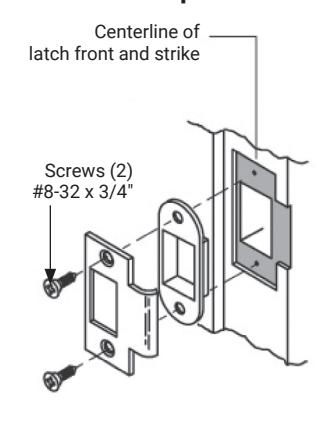
A. Mark and Drill Holes C. Frame Preparation

B. Final Door Prep
WARNING
This product can expose you to lead which is known to the state of California to cause cancer and birth defects or other reproductive harm. For more information go to www.P65warnings.ca.gov.
WARNING
Attention Installer: Any retrofit or other field modification to a fire rated opening can potentially impact the fire rating of the opening, and ASSA ABLOY makes no representations or warranties concerning what such impact may be in any specific situation. When retrofitting any portion of an existing fire-rated opening, or specifying and installing a new fire-rated opening, please consult with a code specialist or local code official (Authority Having Jurisdiction) to ensure compliance with all applicable codes and ratings.
80-9510-0070-000 04/24

RL Series Tubular Lock Installation Instructions
4. Installation
A. Passage (RL201) and Privacy (RL202) Functions
IMPORTANT
For proper installation, the spring housing assembly with sticker should have arrow pointing towards latchbolt and be legible during installation. See Figure 1 .
-
Install latch using (2) #8-32 x 3/4" screws. Install loosely; tighten after step #5.
- a. For RL202 privacy function, the threaded hole on locking piece must be toward the inside of the door. See Figure 2 .
- 2. Slide outside assembly into bore.
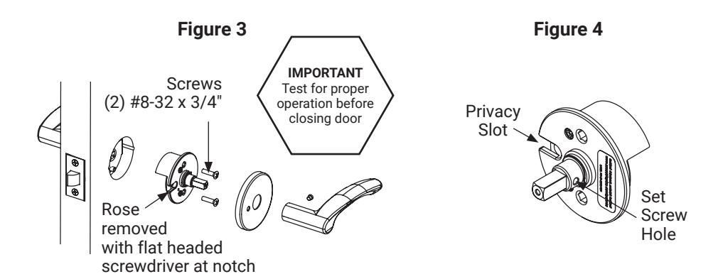
- Install inside spring housing assembly using (2) #8-32 x 3/4" screws. Note location for set screw, see Figure 3.
- Install rose onto spring housing assembly. See page 4 if Square Roses.
-
5. Install lever onto spindle. Insert set screw into hole in lever and tighten.
- a. If lever set screw does not align with the threaded hole in the spring housing assembly, remove spindle and rotate the hub 180 degrees. Ensure the set screw orientation in the hub is opposite the privacy slot in the housing, see Figure 4.
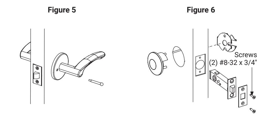
- 6. For RL202 privacy function, install push button. See Figure 5 .
B. Communicating (RL228) Function
- 1. Install latch using (2) #8-32 x 3/4" screws. Install loosely; tighten after step #5.
- Slide blank outside rose assembly into bore, see Figure 6.
- 3. Install inside spring housing assembly, rose and lever same as #3, 4 & 5 above.
Figure 2 Install first for fire rated option Screws (2) #8-32 x 3/4" Locking Piece
80-9510-0070-000 04/24
RL Series
Tubular Lock Installation Instructions

4. Installation, Continued.
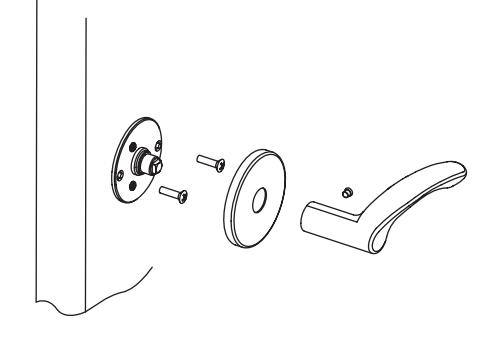
C. Single Lever Pull (RL255S) Function
- 1. Install inside mounting plate assembly using (2) #8-32 x 3/4" screws. Note location for set screw.
- 2. Install rose onto spring housing assembly. See page 4 if Square Roses.
- 3. Install lever onto spindle. Insert set screw into hole in lever and tighten. See Figure 7 .
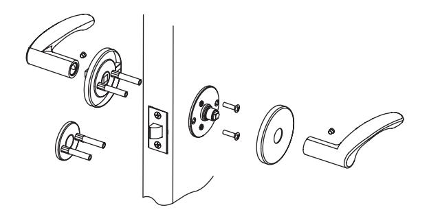
D. Through-bolted Single Lever Pull (RL255) and Double Lever Pull (RL255D) Functions
- 1. Install through-bolt assembly from outside.
- 2. Install inside mounting plate assembly using (2) #8-32 x 3/4" screws. Note location for set screw.
- 3. Install rose onto spring housing assembly. See page 4 if Square Roses.
- 4. Install lever onto spindle. Insert set screw into hole in lever and tighten. Repeat process for outside lever (RL255D Function only). See Figure 8 .
Figure 7 Figure 8

5. Square Rose Installation (Figure 9)
- 1. Install latch, outside assembly and inside spring housing assembly per function.
- 2. Position square mounting plate over spring housing, See Figure 10 .
- 3. Drill two centered pilot holes for the #6-32 mounting screws in the upper right and lower left portions of the square mounting plate.
- 4. Loosely attach mounting plate to both sides of the door with screws.
-
5. Square top surface of mounting plate to edge of door.
- a. The right angled square MUST be on the flat surface of the square mounting plate for proper leveling.
- 6. Tighten mounting screws
- 7. Press rose onto mounting plate.
- 8. Install lever onto spindle. Insert set screw into hole in lever and tighten.
Figure 9
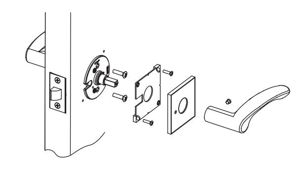
Figure 10
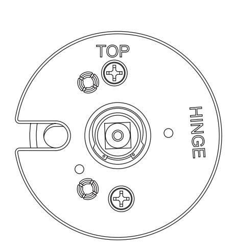
Spring Housing Spring Housing
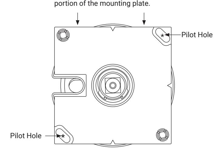
NOTE: Note: To level plate, place a right angle square on the flat
Scan with your camera on your phone to see a video of this installation step.

WARNING
This product can expose you to lead which is known to the state of California to cause cancer and birth defects or other reproductive harm. For more information go to www.P65warnings.ca.gov.
80-9510-0070-000 04/24