ASSA ABLOY ACCENTRA PR3000, 3020 Series, Parallel Rigid and Holder, Stop Arms, Non-Hold Open & Hold_80-9303-2209-010
Open the original PDF document
View PDF

3000 Series
Parallel Rigid (PR), Holder/Stop, Non-Hold Open and Hold Open Installation Instructions Holder/Stop with Thumbturn Arms
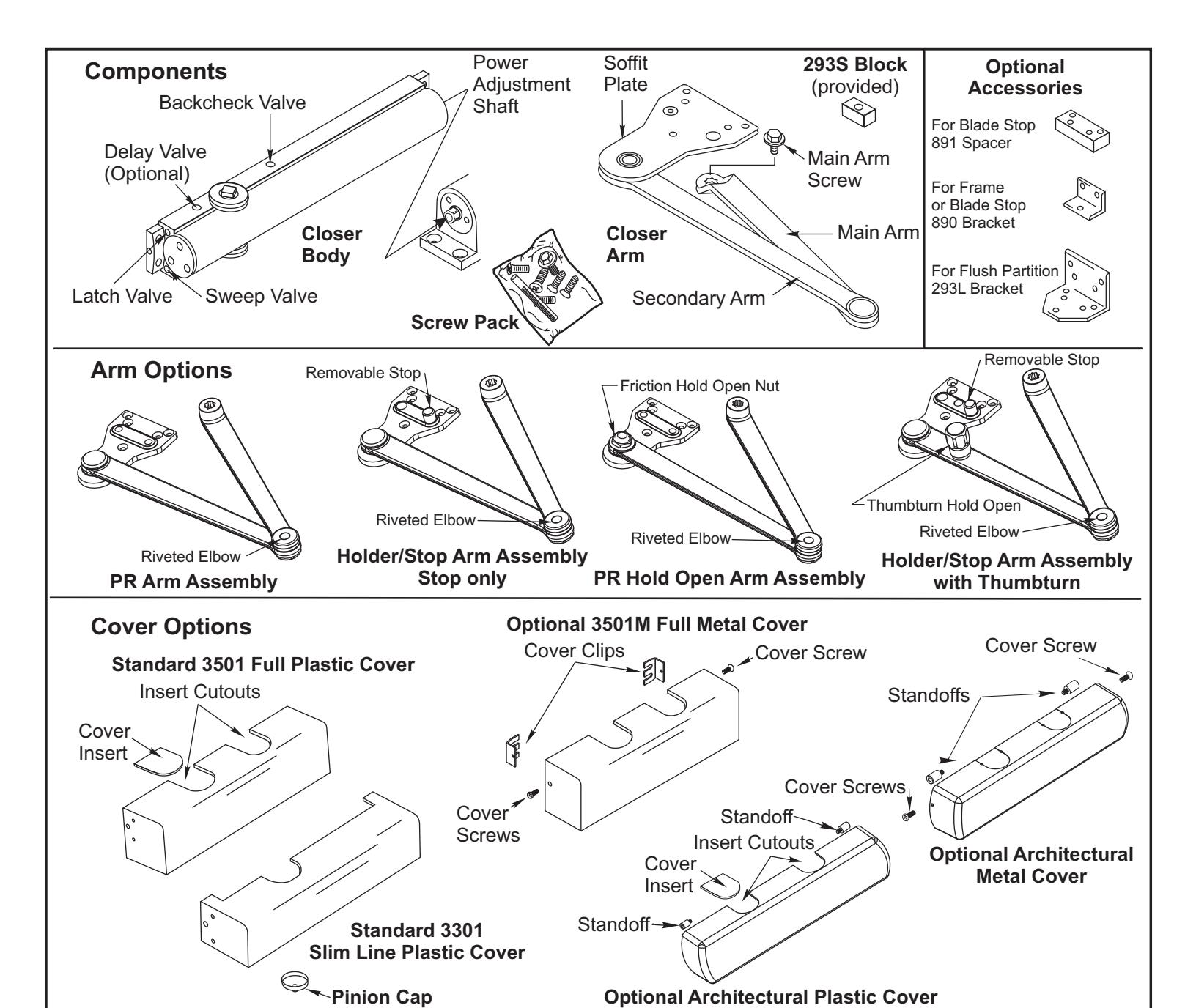
Additional Closer Options:
- "DL" indicates Delayed Action closing.
- "T" indicates Thumbturn actuated hold open control; units are handed.
Optional Accessories:
- 3148 Drop Plate (use with slim cover or no cover)
- 3158 Drop Plate (use with full cover)
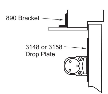
- 293L, 293S, 890, 891 Soffit Plate Accessories.
An incorrectly installed or improperly adjusted door closer can cause property damage or personal injury. These instructions should be followed to avoid the possibility of CAUTION misapplication or misadjustment.
Model Numbers Included:
PR3301/ PR330X PR3311/ PR331X* 3321(T) / 332X(T) PR3501/ PR350X PR3511/ PR351X* 3521(T) / 352X(T)
Note 'X' Designates Size 2, 3, 4, 5, or 6
*Hold open units are handed
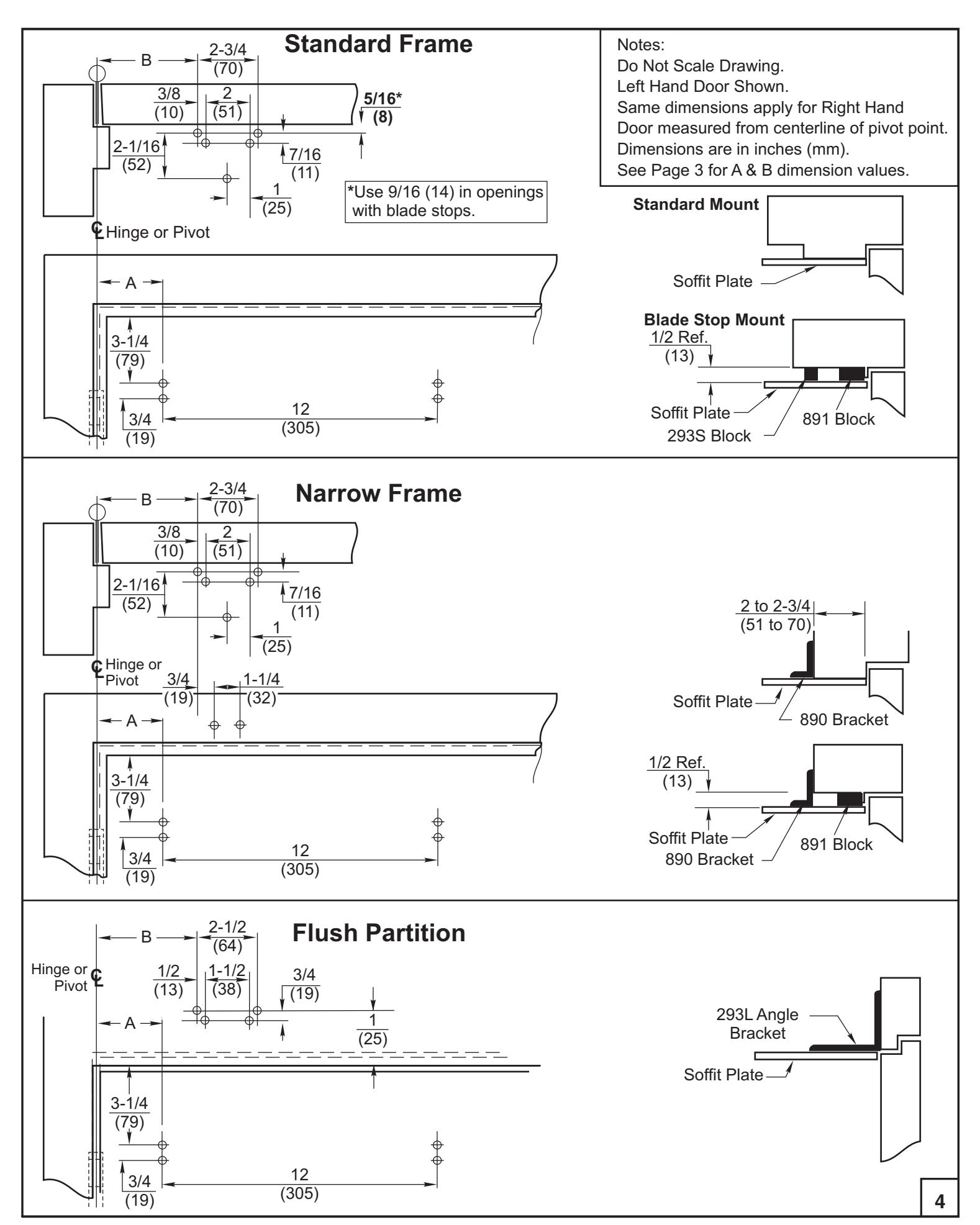
NOTE: For special applications a separate door and frame preparation template is packed with these instructions. In those cases, use this instruction sheet for installation sequence and closer adjustments only.
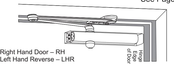
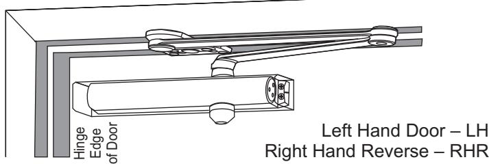
Standard Frame Installation
Closer mounts on opposite to hinge (push) side of door. PR3301 Parallel Rigid Non Hold Open arm illustrated. Slim Line Cover shown. See Pages 3 and 4
CAUTION
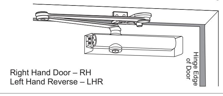
Narrow Frame Installation
Closer mounts on opposite to hinge (push) side of door. 3521 Holder/Stop arm illustrated. Full Cover shown. 890 and 891 accessories required for this application (supplied separately).
See Pages 3 and 4
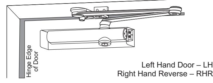
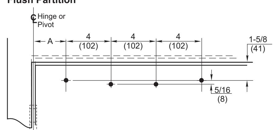
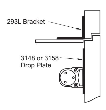
Flush Partition Installation
Closer mounts on opposite to hinge (push) side of door. 3521T Holder/Stop arm with Thumbturn Hold Open illustrated. Closer Cover not shown. 293L accessory required for this application (supplied separately).
See Pages 3 and 4
| Preparation for Fasteners | ||||||
|---|---|---|---|---|---|---|
| Fasteners | Door or Frame | Drill-Sizes | ||||
| Solf Drilling Scrow | Aluminum or Metal | No drill required | ||||
| Standard | Self-Drilling Screw | Wood |
3/16" (4.80 mm)
Pilot hole required |
|||
| 1/4" - 20 machine screw | Metal |
Drill: #7 (0.201" dia.) (5mm)
Tap: 1/4" - 20 |
||||
| Sleeve nuts and bolts |
Hollow
Metal |
9/32" (7 mm) thru;
3/8" (9.5 mm) door face opposite to closer |
||||
| Optional | Aluminum or Wood | 3/8" (9.5 mm) through | ||||
| Through-bolts and grommet-nuts | All |
9/32" (7 mm) thru;
3/8" (9.5 mm) dia. x 3/8" (9.5 mm) deep on door opposite to closer |
||||
Note: Wood doors MUST be pre-drilled when using Self-Drilling Screws.
80-9303-2209-010 (10-10)
Installation Instructions
- Select angle of opening and use dimensions shown on Page 4 and Dimension Chart below to locate 4 holes on stop side of door for closer body and 5 holes on stop and/or rabbet for Soffit Plate. For applications not covered in these instructions, a separate template will be required. or 3148 or 3158 Drop Plate, only if required
- Prepare door and frame for fasteners. See "Preparation for Fasteners", Page 2.
- Set closer power for door size using Power Adjustment Chart below. Use 5/16" (8mm) wrench to adjust Power Adjustment Shaft ... 20 turns maximum. Turn nut to to power. See Page 6, Figure 3 for the illustration of this step. CLOCKWISE Increase, COUNTER-CLOCKWISE Decrease
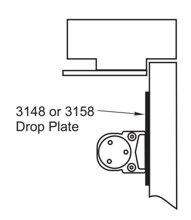
- Mount 3148 or 3158 Drop Plate ... only if required (see Page 5).
- Install closer with Note: If using full metal cover, cover mounting clips must be slipped under ends of closer when closer is being mounted. Clips should project 1/4" (6mm) beyond each end of closer. power adjustment screw toward hinge edge of door.
- With door closed, use wrench to rotate pinion shaft as illustrated below, see Arm Mounting Details. Caution: Closer pinion is under spring tension and may be difficult to rotate.
-
Install Main Arm: Close valves and , then turn pinion shaft more than 50° to permit proper alignment of arm mark with pinion flat -
'S' 'L'
- for hand door. 'L' Left
- for hand door. 'R' Right
See "Main Arm Installation Instructions" below.
- (see page 6) before installing cover ... Make closer adjustments CAUTION: Do not back valves out of closer completely or a leak will result .
- Reopen valves by turning counter clockwise.
- ... use spacer blocks 293S or 891, if required. With door closed, align soffit plate with mounting holes in frame. Fasten soffit plate to frame with flat head screws provided.
- ° using parallel mount. Install cover (see page 6). Architectural Covers CAN NOT be used for doors swinging over 120 NOTE:
| Installation Dimensions Chart | |||||||||||
|---|---|---|---|---|---|---|---|---|---|---|---|
| Dim |
85°-
90° |
90°-
95° |
95°-
100° |
100°-
105° |
105°-
110° |
110°-
115° |
115°-
120° |
120°-
180° |
|||
| PR3301/PR3501 | A |
in.
(mm) |
3-3/4
(95) |
1-1/4
(32) |
|||||||
| B |
in.
(mm) |
9-1/2
(241) |
7
(178) |
||||||||
|
Butt
Hinges |
A |
in.
(mm) |
5-5/8
(143) |
4-7/8
(124) |
4-1/8
(105) |
3-1/2
(89) |
2-7/8
(73) |
2-1/4
(57) |
|||
| 3321/3521 |
or
Offset Pivots |
B |
in.
(mm) |
11-1/8
(283) |
10-3/8
(264) |
9-5/8
(244) |
9
(229) |
8-3/8
(213) |
7-7/8
(200) |
||
|
Center
Pivots |
A |
in.
(mm) |
5-1/2
(140) |
4-3/4
(121) |
3-7/8
(98) |
3-1/4
(83) |
2-5/8
(67) |
2
(51) |
|||
| B |
in.
(mm) |
11
(279) |
10-1/4
(260) |
9-3/8
(238) |
8-3/4
(222) |
8-1/8
(206) |
7-5/8
(194) |
||||
| Arm Mounting Detail |
|---|
|
Start (wrench) here
Rotate Install arm here (see below for details) |
| Power Adjustment Chart | ||||||
|---|---|---|---|---|---|---|
| Full Clockwise Turns of Closer Power Adjustment Shaft | ||||||
|
Door
Size |
33-36 in
28-32 in 0.7-0.8 m 0.85-0.9 m |
37-42 in
0.95-1.05 m |
43-48 in
1.1-1.2 m |
|||
| Interior | 7 | 10 | 13 | 16 | ||
| PR3301/PR3501 | Exterior | 9 | 12 | 15 | 18 | |
| Interior | 9 | 11 | 13 | 15 | ||
| 3321/3521 | Exterior | 10 | 12 | 14 | 16 | |
NOTE: Maximum of 20 turns (360°) of Power Adjustment Screw. Closer is shipped set at mid power setting.
| Main Arm Installation Instructions | |||||
|---|---|---|---|---|---|
|
Left Hand Door
Power Adjustment Screw |
Door Swing
Right Hand Door Power Adjustment Screw |
||||
|
R
Pinion Flat Z S L Y Arm Mark |
Pinion Flat
L Y S R Z Arm Mark |
||||
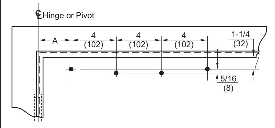
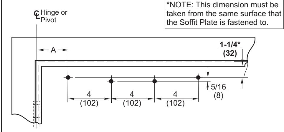
3
3148 or 3158 Drop Plate Mounting Holes
Standard Frame
Narrow Frame
Flush Partition
Thumbturn Hold-Open Feature
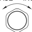
The Thumbturn Hold-Open feature is controlled by the knob located on the arm of the unit. Turning this knob clockwise will engage the Hold-Open mechanism and increase the Hold-Open force. Turning this knob counterclockwise will reduce the Hold-Open force and disengage the Hold-Open mechanism. DECREASE -- INCREASE
Thumbturn Action (Units suffixed "T")
Friction Hold-Open Feature
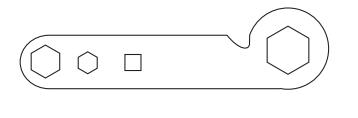
Hold door open to opening angle desired and tighten holderadjustment-nut (wrench supplied) or use 1" Box or Open End wrench.
80-9303-2209-010 (10-10)
5
Unit Adjustment
Closing Power Adjustment–
Using "Power Adjustment Chart" from Page 3, select the correct number of turns for power adjustment shaft that corresponds with the installation. With 5/16" (8mm) wrench, rotate adjustment shaft full 360° clockwise turns to desired setting. After closer has been installed and proper adjustments made to the sweep and latch, it may be necessary to readjust spring power for good closing action.
Closing Speed Controls (Figure 1A or 1B and 2.)
- Valve "S" Controls Sweep Range.
- Valve "L" Controls Latch Range.
- Valve "D" Controls Delay Range (optional).
Control Valve Adjustments
(See Figure 2.)
Hex Key
LATCH LATCH Delayed Action Closing Cycle 1B Closing Speed Controls Figure 1. SWEEP SWEEP Attention: Adjust Closing Speed Time to between 4 to 7 seconds from 90°. Use of the door by handicapped, elderly or small children may require greater closing time. CLOSED Standard Closing Cycle 1A D ELA Y R ANG E 10° 10° 70° CAUTION: DO NOT BACK VALVES OUT OF CLOSER OR A LEAK WILL RESULT. Closing Speed Controls Figure 2. Slow 1/8" Latch Valve Delay Valve
Fast Sweep Valve Closing Power Control Figure 3. Increase 5/16" Socket or Adjustable Wrench Power Adjustment Shaft NOTE: Maximum of 20 360° turns of Power Adjustment Shaft
Decrease
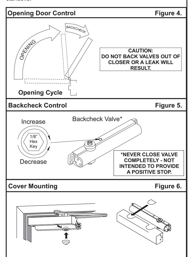
Opening Cycle
"Backcheck" valve controls the strength of cushioning in Backcheck Range. NEVER close this valve completely – it is not to provide a positive stop. (see Figure 4 and Figure 5).
Cover (Figure 6)– Full cover: Slide cover insert into the un-used cutout in cover. Install cover using screws provided.
Narrow cover: Install cover using screws provided. Install pinion cap onto pinion shaft by hand or with a Phillips screw driver - DO NOT OVER TIGHTEN.
Metal cover: Fasten cover to mounting clips with screws provided.
Architectural Metal Cover: Remove cover insert where pinion is located. Install standoffs in ends of closer. Install cover using screws provided.
Architectural Plastic Cover: Slide cover insert into the un-used cutout in cover. Install standoffs in ends of closer. Snap cover over standoffs.
Yale Locks & Hardware is a division of Yale Security Inc., an ASSA ABLOY Group company. 3000 Hwy 74 East, Monroe, NC 28112 • Product Support Tel 800.438.1951 • Fax 800.338.0965 • www.yalelocks.com
Yale® is a registered trademark of Yale Security Inc., an ASSA ABLOY Group company. Other products' brand names may be trademarks or registered trademarks of their respective owners and are mentioned for reference purposes only. These materials are protected under U.S. copyright laws. All contents current at time of publication.Yale Security Inc. reserves the right to change availability of any item in this catalog, its design, construction, and/or its materials. Copyright © 2004, 2010, Yale Security Inc., an ASSA ABLOY Group company. All rights reserved. Reproduction in whole or in part without the express written permission of Yale Security Inc., an ASSA ABLOY Group company is prohibited.
YALE , with its unique global reach and range of products, is the world's favorite lock.
ASSA ABLOY is the global leader in door opening solutions, dedicated to satisfying end-user needs for security, safety and convenience.
80-9303-2209-010 (10-10)
6