ASSA ABLOY ACCENTRA (P)3300, (P)3500 Series PTD, PTS, PS Units Installation Instructions_80-9303-2211-010
Open the original PDF document
View PDFArm Attachment to Track
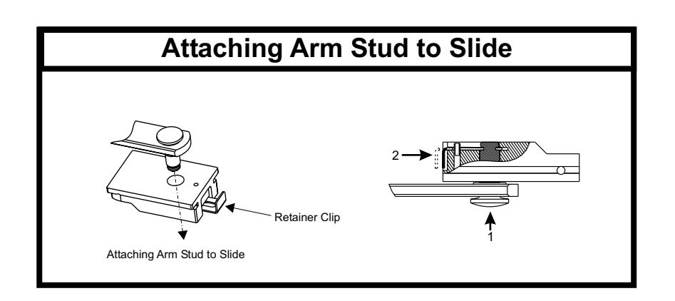
Insert arm stud into slide block in track.
Secure by pushing in on the retainer clip that extends from the slide block, until it is flush with the slide block, see illustration on page 4 of these instructions.
Hold Open Angle:
Place door in the Hold Open position. Remove 9/64" hex drive socket head screw from arm. Open door to desired angle and install hex-drive socket head screw into hole in adjusting rod that is aligned with the hole in the adjusting
Closing Power
Closing Power can be increased by 50%.
To increase power, see Figure 1, rotate "Spring Adjustment Shaft clockwise using a 5/16" socket or adjustable wrench. 20 full turns (360°) will provide maximum available power. Product is shipped set at 10 full turns.
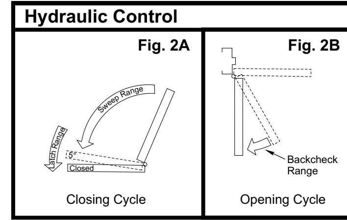
Closing Cycle (hydraulic control)
See figure 2A.
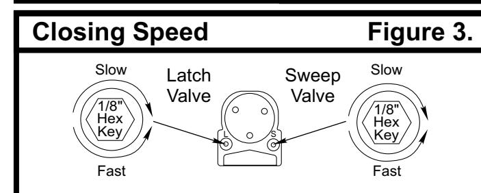
Valve "L" controls door speed in Latch range . Valve "S" controls door speed in Sweep range.
Use 1/8" hex-key furnished and adjust as shown in figure 3.
Opening Cycle (hydraulic control)
See figure 2B.
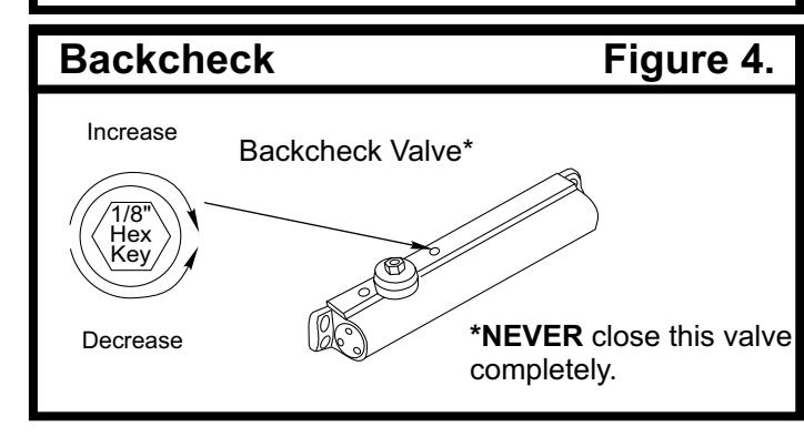
Valve "B" cushions (slows) door opening in the backcheck
Note: Never close this valve completely or damage to closer may occur.
Use 1/8" hex-key furnished and adjust as shown in figure 4.
Installation of Cover:
- Full cover: Slide cover insert into the un-used cutout in cover. Install cover using screws provided.
- Narrow cover: Install cover using screws provided. Install pinion cap onto pinion shaft by hand or with a Phillips screw driver - DO NOT OVER TIGHTEN.
- Full metal cover: Fasten cover to mounting clips with screws provided.
- Architectural plastic cover *: Slide cover insert into the un-used cutout in cover. Install standoffs in ends of closer. Snap cover onto standoffs.
- Architectural metal cover *: Remove cover insert where pinion is located. Install standoffs in ends of closer. Install cover using screws provided
- Metal hook-up box cover: Fasten with four screws provided.
- * NOTE: Architectural Covers CAN NOT be used for stop (push) side applications
Hold Open Power Adjustment:
If more hold open power is required, the power may be increased by turning the adjustment screw in the end of the track nearest the hinges. Use 9/64" hex wrench provided and rotate adjustment screw clockwise to increase holding power.
Closing Power Control Figure 1. Increase NOTE: Maximum of 20 360° turns of Spring Adjustment Shaft Spring Adjustment Shaft Decrease
IMPORTANT!
After making all wiring connections:
- Turn power to unit "on". "PTD" units only: green LED should be illuminated.
- Open door to the hold open position. Manually pull door out of hold open and release ... door should close.
- Again, open door to the hold open position. Depress "Test Switch" button on the hook-up board ... door
- · Fasten hook-up box cover with four screws provided
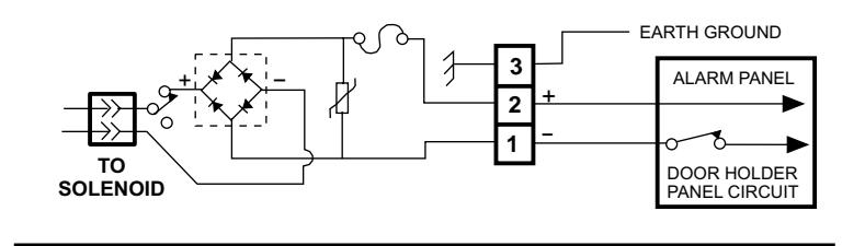
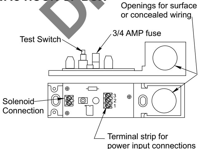
WIRING INSTRUCTION 24VAC/DC or 120VAC
Input voltage supplied must match label rating on hook-up box.
TYPICAL WIRING DIAGRAM
24VAC/DC HOOK-UP BOX
Page 6
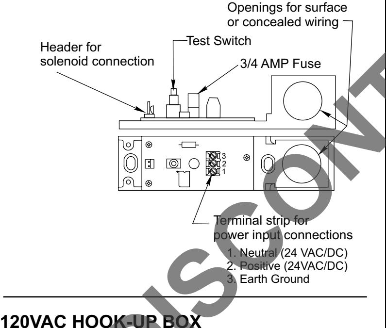
1. Neutral (120VAC/DC)
2. Positive (120VAC/DC)
3. Earth Ground
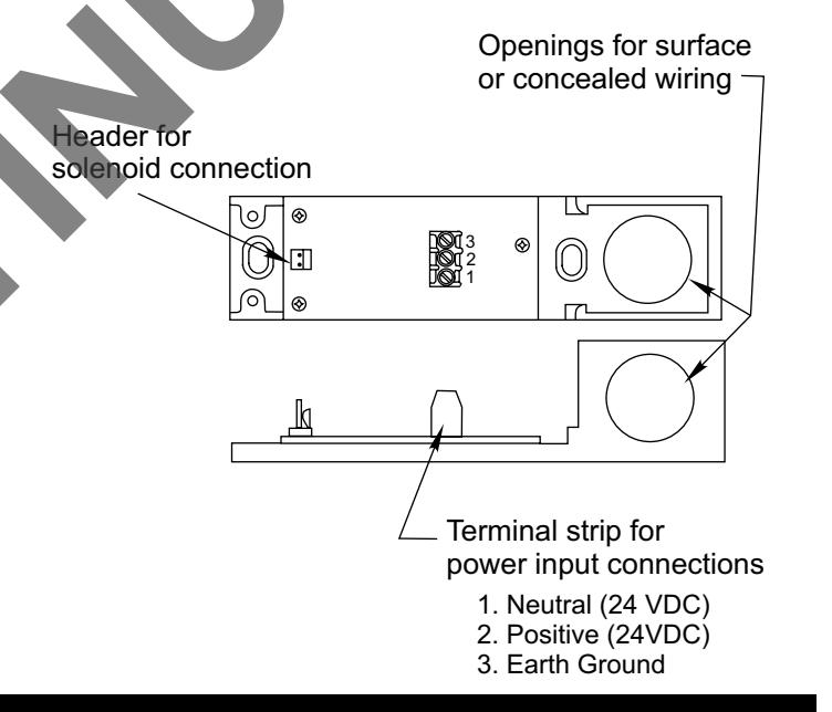
WIRING INSTRUCTION 24VDC ONLY
Typical wiring terminals 1 and 2 will connect to terminals 5 and 6 from "PTD" unit
TYPICAL WIRING DIAGRAM
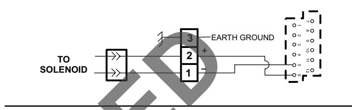
HOOK-UP BO
This product is now proudly being offered under the ASSA ABLOY ACCENTRA™ brand, effective June 20, 2023. Visit YaleCommercial.com/en/Today for support and information
For PTD Models:
Refer to "Power Track" "Wiring Instructions" No. 80-9342-0900-021 for making wiring conenctions.
SPECIFICATIONS:
| 120VAC | 24VAC | 24VDC | |
|---|---|---|---|
| Voltage | 120VAC + 10%-15% | 24VAC + 10%-15% | 24VDC + 10% -15% |
| Current | .018 AMPS | .090 AMPS | .090 AMPS |
NOTES: 1. Maximum wire size is 14AWG.
2. All wiring and connections use standard wiring practice conforming with local wiring codes.

Installation Instructions
Combination Door Closer-Holder and Releasing Device WITHOUT and WITH Integral Smoke Detector

Cover with Insert
Narrow Cover
CAUTION
An incorrectly installed or improperly adjusted door closer can cause property amage or personal injury. These instruction should be followed to avoid the possibility of misapplication or misadjustment.
Power Track Series Master Unit - PTD (with detector) Support Unit - PT (without detector) Slave Unit - PTS (without detector)
Hinge (Pull) Side of Stop (Push) Side of Door Application Door Application
3300 PTD P3300 PTD 3500 PTD P3500 PTD 3300 PT/PTS P3300 PT/PTS 3500 PT/PTS P3500 PT/PTS
Models
NOTE: For wiring of PTD models, see "Power Track" "Wiring Instructions" No. 80-9342-0900-021
Optional Architectural
Metal Cover
NOTE: For special applications a separate door and frame preparation template is packed with these instructions. Use this instruction sheet for installation sequence and closer adjustments only.
Use of an auxiliary door stop is always recommended.
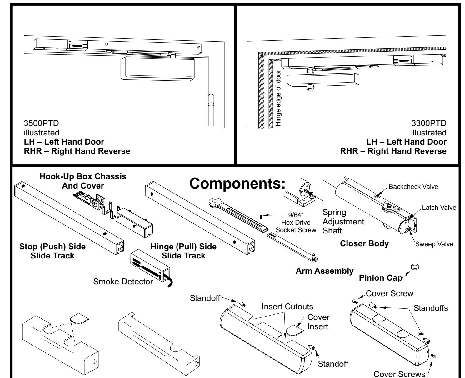
Optional Architectural Plastic
Full Cover with Insert
80-9303-2211-010 (04-06) Page 5
Hinge (Pull) Side Applications
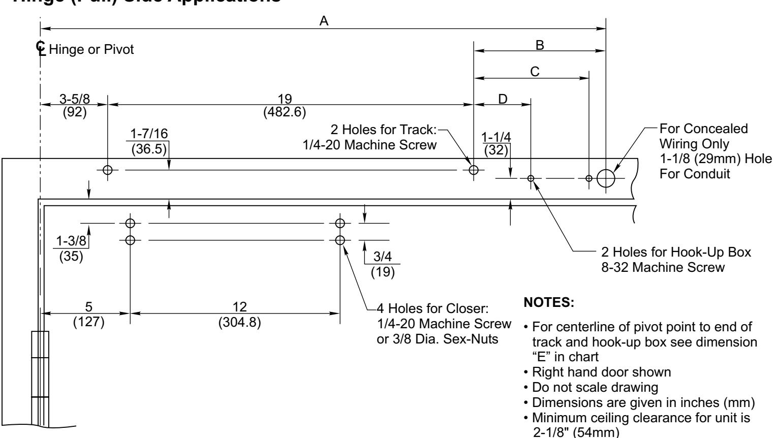
| Α | В | С | D | Е | |
|---|---|---|---|---|---|
| PT/PTS | 31-1/16 (789) | 8-7/16 (214) | 7-5/8 (194) | 4-3/8 (111) | 32-3/16 (818) |
| PTD | 34-11/16 (881) | 12-1/16 (306) | 11-1/4 (286) | 8 (203) | 35-13/16 (910) |
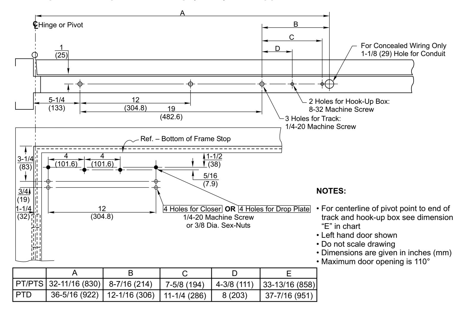
- For Concealed Wire Applications Only: Locate and drill 1-1/8" (29mm) diameter hole in frame face for the conduit.
- Locate mounting holes in door and frame using above template: Door – 4 holes for Closer
Frame – 2 holes for Track. 2 holes for Hook-up Box
- 3. Prepare mounting holes for fasteners using "Preparation for Fasteners" chart on page 4.
- 4. Fasten Track Assembly to frame with spring buffer toward hinge edge of frame and open side facing down.
- Remove metal cover and straps from hook-up box assy.. NOTE: Units with a 120V to 24V transformer require that hook-up board be removed from chassis to enable mounting.
- Fasten Hook-up Box Straps and Chassis to frame with conduit hole openings away from hinge edge of frame. NOTES: Place Hook-Up Box straps between frame and chassis. Special conduit nut supplied to anchor 3/4" conduit fitting.
Maximum door opening is 110°
- 7. Mount CLOSER BODY to door with valve end of closer toward hinge edge of door.
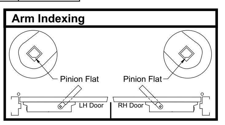
- 8. Adjust arm to shortest length and install 9/64" hex drive socket head screw from screw pack.
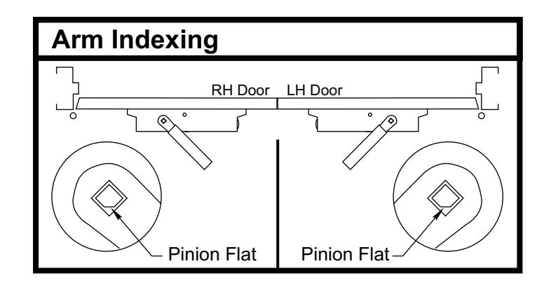
- 9. Place slide arm on pinion shaft using Arm Indexing instructions above.
- 10. Secure arm with arm washer and arm screw.
- 11.Insert arm stud into slide block in track assembly. Secure by pushing in on the retainer clip that extends from the slide block in the track, until it is flush with the slide block (see Attaching Arm Stud to Slide on page 4).
Stop (Push) Side Applications
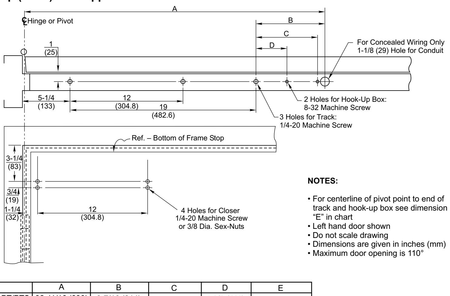
| А | В | С | D | Е | |
|---|---|---|---|---|---|
| PT/PTS | 32-11/16 (830) | 8-7/16 (214) | 7-5/8 (194) | 4-3/8 (111) | 33-13/16 (858) |
| PTD | 36-5/16 (922) | 12-1/16 (306) | 11-1/4 (286) | 8 (203) | 37-7/16 (951) |
- 1. For Concealed Wire Applications Only:
- Locate and drill 1-1/8" (29mm) diameter hole in frame soffit for the conduit.
-
Locate mounting holes in door and frame using above template:
- Door 4 holes for Closer or 8148 Drop Plate (see page 4) Frame 3 holes for Track. 2 holes for Hook-up Box
- 3. Prepare mounting holes for fasteners using "Preparation for Fasteners" chart on page 4.
- 4. Fasten Track Assembly to frame with spring buffer toward hinge edge of frame and open side facing down.
- Remove metal cover and straps from hook-up box assy.. NOTE: Units with a 120V to 24V transformer require that hook-up board be removed from chassis to enable mounting.
- Fasten Hook-up Box Straps and Chassis to frame with conduit hole openings away from hinge edge of frame. NOTES: Place Hook-Up Box straps between frame and chassis. Special conduit nut supplied to anchor 3/4" conduit fitting.
- Mount CLOSER BODY (or Drop Plate and then Closer Body) to door with spring adjustment nut toward hinge edge of door.
- 8. Adjust arm to shortest length and install 9/64" hex drive socket head screw from screw pack.
- Place slide arm on pinion shaft using Arm Indexing instructions above.
- 10. Secure arm with arm washer and arm screw.
- 11.Insert arm stud into slide block in track assembly. Secure by pushing in on the retainer clip that extends from the slide block in the track, until it is flush with the slide block (see Attaching Arm Stud to Slide on page 4).
3148 Drop Plate Template with Stop (Push) Side Application
| Preparation for Fasteners | |||
|---|---|---|---|
| Fasteners | Opening | Fastener Preparation | |
| 8-32 Machine Screw | Metal Frame |
Drill: #29 [.136" (3.45mm) dia.]
8-32 UNC Tap |
|
| 1/4-20 Machine Screw |
Metal
Door or Frame |
Drill: #7 [.201" (5.10mm) dia.]
1/4"-20 UNC Tap |
|
| 3/8 Dia. Sex Nut |
Wood or
Composite Door |
3/8" [.375" (9.50mm) dia.]
through |
|
Page 2 80-9303-2211-010 (04-06) 80-9303-2211-010 (04-06) 80-9303-2211-010 (04-06) 80-9303-2211-010 (04-06)