ASSA ABLOY ACCENTRA Onity Trim Conversion Kit (Product Discontinued) Installation Instructions_80-8470-0100-000
Open the original PDF document
View PDFCopyright 2005 Yale Security Inc. all rights
reserved.
(865) 986-8630 (Fax)
Website: www.yalecommercial.com
C
ONITY TRIM CONVERSION KIT 80-8470-0100-000 (Rev. A) R
This instruction sheet will guide you through the conversion and mounting of a Tesa Entry Systems Onity trim. This conversion is required in order to use an Onity trim with Yale Exit devices. This kit can be used on the following current Yale Exits: 2100, 2110, 2150, 7100, 7110, 7150, 7120, 7160, 7170. If the Exit Device was ordered to work with an Onity trim, the trim slide (Item #1) will be already installed in the device and the #1/4-20 screws (Item #4) will be packaged with the device. R R
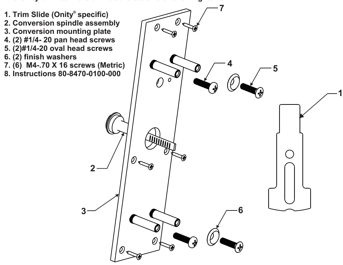
The Onity trim conversion kit consists of the following items.
Note: It is recommended that the trim be in an unlocked state prior to the conversion. Refer to the trim instructions for proper unlocking procedures.
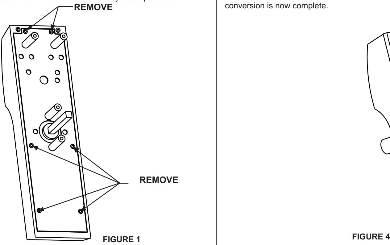
Step 1 Removal of the rear mounting plate.
Flip the trim over so the back is facing you. Notice the (6) Torx screws that hold the rear cover on (figure 1). These screws need to be removed. A 5/64" Allen wrench will work to remove these screws if a Torx bit is not available. Carefully remove the cover. This cover will not be reused for the conversion and may be disposed of.
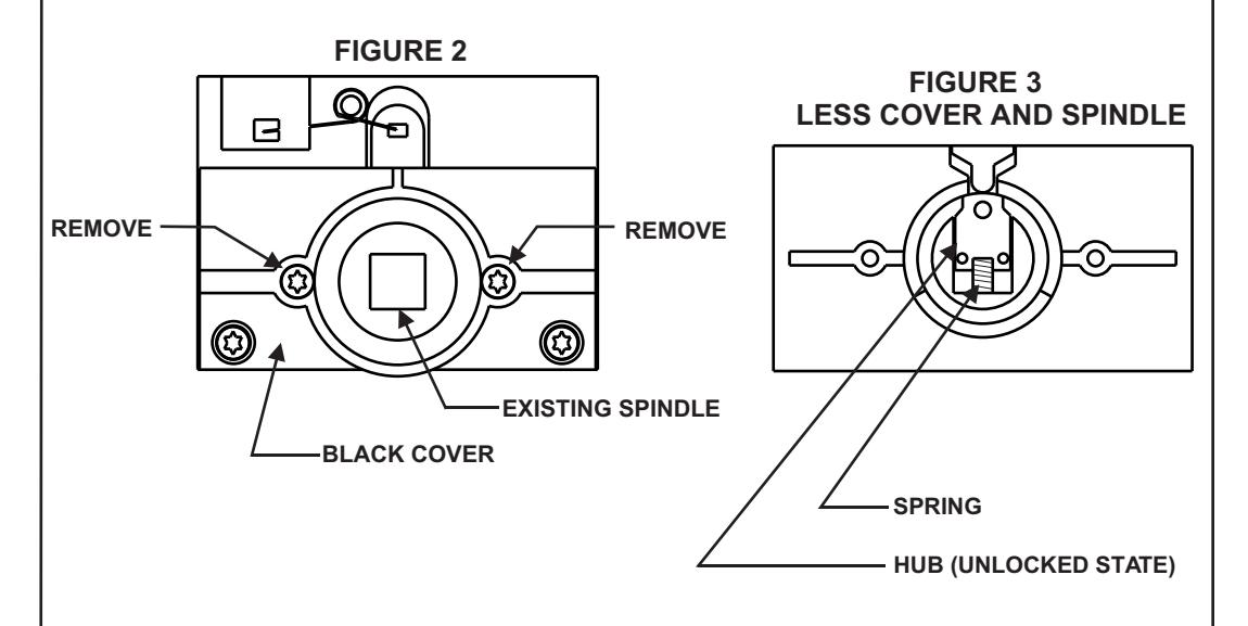
Step 2 Removal of current spindle and installation of new spindle assembly.
Note: It is critical that the trim back is facing you during this step. If the trim is tilted on its side or turned over critical parts may be lost.
Remove the foam washer from the top of the black cover. This will expose two screws that need to be removed (figure 2). Again these are Torx and a 5/64" allen will remove them. CAREFULLY lift the cover and spindle assembly straight up and out. Notice the hub and spring (figure 3). These are the critical parts mentioned in the beginning of this step. Insert the new conversion spindle through the hole in the black cover and install it as a unit onto the trim. Secure the screws and rotate the spindle so the tail is in the vertical position. The old spindle is no longer needed and may be disposed of.
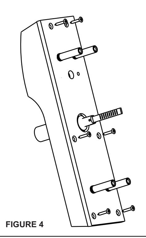
Step 3 Installation of Conversion Mounting Plate
After the spindle is converted, the Conversion Mounting Plate must be installed. With the studs in the plate facing up (figure 4) align the mounting holes in the plate with the threaded holes in the trim. Start all (6) M4-0.7 screws. After all screws are started secure all six. The trim part of the conversion is now complete.
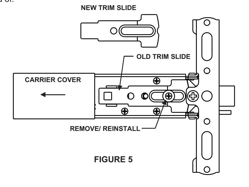
Step 4 Exit Device Trim Slide conversion
Note: This step is not required if the Exit Device was ordered from the factory for use with an Onity trim.
The only part required to be replaced is the Trim Slide. To accomplish this, slide the carrier cover back about six inches. The black plastic part is the trim slide. It is replaced by removing the Phillips screw and spacer. Lift the Trim Slide out and replace it with the conversion Trim Slide (with one hole). Install the spacer and screw and tighten securely. After installation move the Trim Slide back and forth several times to insure it activates the bolt with out binding. The old Trim Slide is no longer needed and may be disposed of.
Step 5 Prepping the door.
Note: The template on the back of this instruction sheet is to be used in conjunction with the instructions and templates packaged with the specific Yale device used. Additional door prep may be required.
Using the device instructions, measure the proper location of the vertical and horizontal center lines. Using the template on the back of this sheet, align the center lines of the template with the measured center lines. Using a center punch, mark the hole locations on the door face. Remove and repeat on the other side of the door. Once all holes are marked and rechecked, drill the holes but only through half of the door. Repeat on the other side. This prevents splintering of the door and insures the holes are straight. If additional prepping of the door is required, do so at this time.
Step 6 Mounting the trim and device.
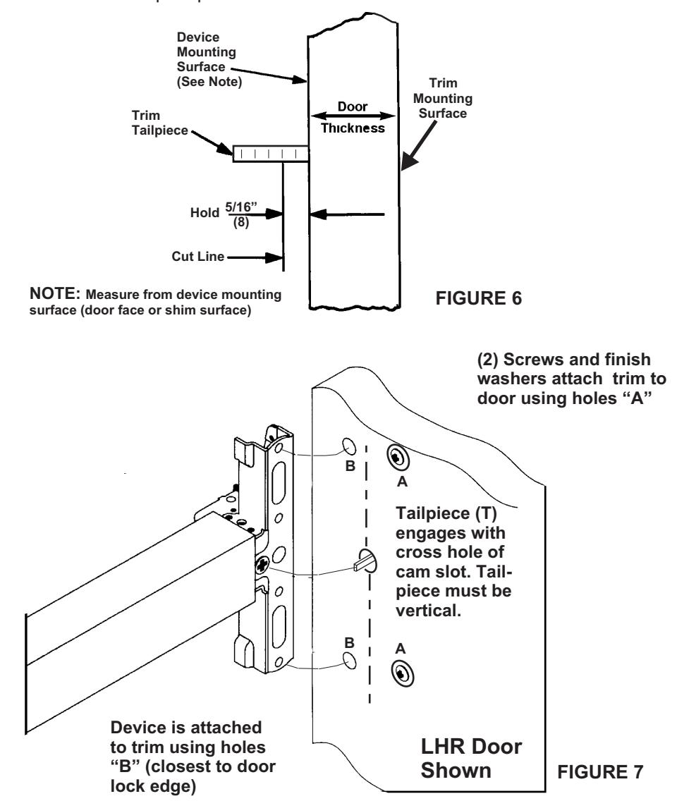
Note: The standard tailpiece can be used on door thicknesses from 1-3/4 to 2". If a longer tailpiece is needed it must be special ordered. If this special tailpiece was ordered with this kit, it must be sized for proper door thickness. Failure to do so will result in damage to the Exit Device. See figure 6 for proper instructions and dimensions (5/16").
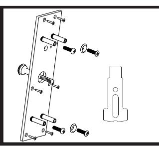
Insert the trim into the prep. Install (2) 1/4-20 screws into holes "A" (figure 7) (Holes furthest from the door edge). Note: Rotate the tailpiece so that it is vertical (figure 7). Failure to follow this step will prevent the package working correctly. Align the tailpiece of the trim with the device. Hold the device up to the door as the other (2) 1/4-20 screws are inserted through the holes in the device head and through holes "B". Tighten securely. Unlock the trim (per trim instructions) work the lever to insure the latch bolt retracts and extends fully without binding. Continue the install per specific device instructions.