ASSA ABLOY ACCENTRA NTX700 Controller-Updater Installation Guide_80-8150-0043-010
Open the original PDF document
View PDF

Multi-Family Management System
Installation Guide NTX700 Controller-Updater


1. Introduction
Used together in a one-to-one relationship, the controller and the credential updater are referred to as the Online Updater. The online updater can operate both as a credential enrollment station and as a single door controller to operate an electrified strike, magnetic lock, gate operator, and more.
The ASSA ABLOY ACCENTRA™ Multi-Family Solution requires at least one Online Updater to serve several functions within the ASSA ABLOY ACCENTRA Ecosystem:
- Activates new physical credentials (cards, fobs, vehicle credentials) for residents, guests, and staff
- Transmits current access rights to physical credentials at time of presentation
- Ensures physical credentials are continuously updated through typical daily use
- Reads credential access permissions to grant or deny access to online opening
- Reads audit information including access history, lock battery status, and other lock events from the physical credential and transmits to the Multi-Family Management System cloud service
The ASSA ABLOY ACCENTRA Multi-Family Online Updater consists of two major components:
- 1. Door Controller (NTX700-CTLR)
-
2. Credential Updater for NTX600 series (one of the following):
- Credential updater (mini-mullion with pig tail)
- Credential updater (mini-mullion with terminal strip)
- Credential updater (wall switch with pig tail)
- Credential updater (wall switch with terminal strip)
for NTX900 series (one of the following):
- Credential reader (small parking reader)
- Credential reader (large parking reader)
The purpose of this guide is to provide step-by-step instruction for the firsttime installation and use of the online updater/reader. Also noted are technical specifications for both the controller and the updaters/readers as well as LED behavior and typical wiring diagrams.
Things to Consider:
- The recommended wire type for connection between controller and updater/ reader is 24 AWG four-conductor shielded twisted-pair wire, low capacitance 120 Ω characteristic impedance cable type that conforms to EIA RS-485 standard (Belden 3107A or equivalent). Utilize one pair for data and one pair for power.
- The maximum cable length between updater and controller is 1600 feet. For OSDP cable lengths greater than 200 ft (61m) or EMF interference, install 120 Ω resistor across both RS-485 termination ends.
- Use proper cable shield grounding techniques.
- Existing Wiegand wiring may be reused for OSDP. However, standard Wiegand cable may not meet RS-485 twisted pair recommendations. The reuse of cable works best on shorter cable lengths.
- DO NOT install the updater on metal surfaces without appropriate spacer (sold separately, see price book).
- For weather exposed installations, please install with IP65 gasket accessory appropriate for your size updater (sold separately) (NTX600 series).
- An external power supply is required. Please review total power requirements for controller and updaters/readers in Section 5. This does not include power requirements for locks or strikes.

Firewall Settings:
The controller establishes connections to the ACCENTRA cloud using the HTTPS and MQTT protocol on port 443. It also synchronizes time via NTP by establishing connections on port 123. It looks up domain names using DNS on port 53. These outgoing connections need to be accepted for normal operation. During first boot, a controller will, in addition to above, also make an outbound connection using the HTTP protocol, port 80.
| Port Protocol | Domains to Whitelist |
|---|---|
| 80 HTTP |
app.accentra-assaabloy.com
yale.accentra.assaabloy.com |
| 443 HTTPS & MQTT |
app.accentra-assaabloy.com
yale.accentra.assaabloy.com AND rocketfw.s3-eu-west 1.amazonaws.com AND a2118gv0vua4gp.iot.us-east-1.amazonaws.com |
| 123 NTP | n/a |
| 53 DNS | n/a |
2. Installation with NTX600 series
Tools Required:
- Small Phillips head screwdriver
- Small flat head screwdriver
- Wire cutters
Procedure: (J4) (step 3)
To install the controller and updater, do the following:
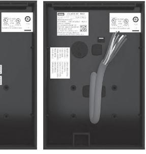
- 1. Remove Controller and Updater from boxes.
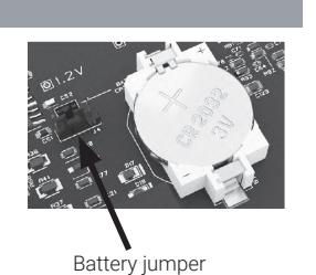
- 2. Remove four (4) Phillips head screws from face of Controller to remove cover.
- 3. Set Battery Jumper (J4) to the ON position.
- 4. Replace gray plastic cover onto Controller unit and secure with four (4) Phillips head screws.
Procedure (con't):
NOTE: The static RAM and the real time clock are backed up by a lithium battery when input power is removed. This battery should be replaced annually.
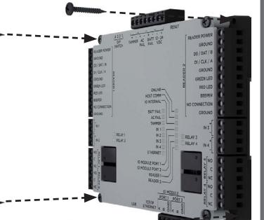
- 5. Mount the controller. Always mount the controller in a secure area. Mount using the supplied screws 0.138" x 1" (3.5mm x 25mm).
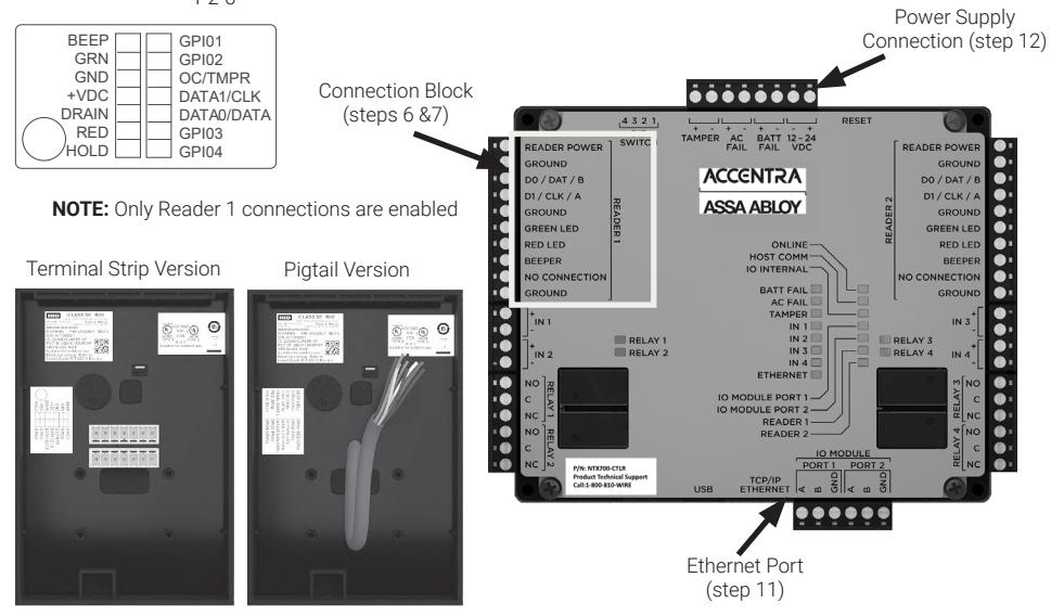
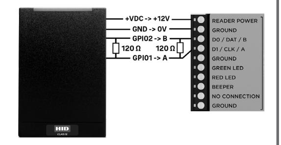
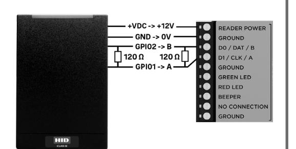
- 6. With flat head screwdriver, loosen four (4) screws on NTX700 controller Reader 1 connection block labeled READER POWER, GROUND, D0/DAT/B, D1/ CLK/A.
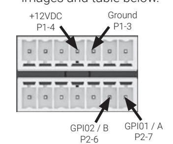
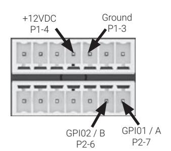
- 7. Insert stripped wires from Updater into holes on connection block as shown in images and table below.
|
Label on
Controller Connector Block |
Reader
Terminal Strip Connections |
Reader
Pigtail Wire Colors |
|
|---|---|---|---|
| READER POWER | +VDC (P1-4) | Red | |
| GROUND | GND (P1-3) | Black | |
| D0/DAT/B | GPI02 (P2-6) | Tan | |
| GPI01 / A | D1/CLK/A | GPI01 (P2-7) | Red/Green |
Procedure (con't):
- 8. If required, insert 120 Ω resistor on reader side terminal strip connector or pigtail wiring and on the controller side as shown in image to the right.
- 9. Tighten four (4) screws on connection block with flat head screwdriver to secure wires.
- 10. For pigtail version, trim stripped ends from remaining wires. These wires are not used and can be tied into a bundle with electrical tape or other appropriate wire insulating material.
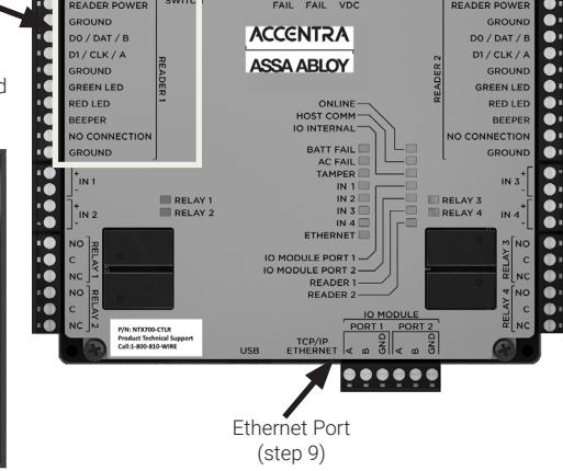
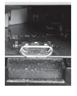
- 11. Plug into Ethernet port as shown in image on the previous page.
- 12. Connect the wires from the power supply to the connection block as shown in the image on the previous page.
NOTE: The boot process is completed when the IO INTERNAL LED is flashing. Controller unit is now ready for configuration into the ACCENTRA Multi-Family Management System using the Configuration app.
WARNING: DO NOT INTERRUPT POWER OR INTERNET DURING THE BOOT PROCESS.
3. Installation with NTX900 series
Tools Required:
- Small Phillips head screwdriver
- Wrench (13mm)
- Small flat head screwdriver
- Ethernet cable
• Wire cutters
NOTE: It is recommended that the set-up and configuration of the controller and NTX900 series parking reader be done on a bench before installing in the desired location.
NOTE: To configure the controller, it is necessary to first attach a NTX600 series updater/reader and then replace the NTX600 updater/reader with the parking reader.
Procedure:
To install the controller and updater, do the following:
- 1. Remove Controller and Updater from boxes.
- 2. Remove four (4) Phillips head screws from face of Controller to remove cover.
- 3. Set Battery Jumper (J4) to the ON position.
- 4. Replace gray plastic cover onto Controller unit and secure with four (4) Phillips head screws.
NOTE: The static RAM and the real time clock are backed up by a lithium battery when input power is removed. This battery should be replaced annually.
- 5. With flat head screwdriver, loosen four (4) screws on NTX700 Reader 1 connection block labeled READER POWER, GROUND, D0/DAT/B, D1/CLK/A.
- 6. Insert stripped wires from Updater into holes on connection block as shown in images and table below.
Battery jumper (J4) (step 3)

|
Label on
Controller Connector Block |
Reader
Terminal Strip Connections |
Reader
Pigtail Wire Colors |
|
|---|---|---|---|
| READER POWER | +VDC (P1-4) | Red | |
| GROUND | GND (P1-3) | Black | |
| D0/DAT/B | GPI02 (P2-6) | Tan | |
| D1/CLK/A | GPI01 (P2-7) | Red/Green | |
Power Supply Connection (step 10)
BEEP GRN +VDC DRAIN RED HOLD GPI01 GPI02 OC/TMPR DATA1/CLK DATA0/DATA GPI04
Connection Block (steps 5 & 6)
NOTE: Only Reader 1 connections are enabled
Terminal Strip Version Pigtail Version
- 7. If necessary, insert 120 Ω resistor on reader side terminal strip connector or pigtail wiring and on the controller side as shown in image to the right.
- 8. Tighten four (4) screws on connection block with flat head screwdriver to secure wires.
- 9. Plug into Ethernet port as shown in image.
10. Connect the wires from the power supply to the connection block as shown in the image on the previous page.
NOTE: The boot process is completed when the IO INTERNAL LED is flashing. Controller unit is now ready for configuration into the ACCENTRA Multi-Family Management System using the Configuration app.
WARNING: DO NOT INTERRUPT POWER OR INTERNET DURING THE BOOT PROCESS.
11. Once the Controller is configured, power down the controller and then disconnect the NTX600 Series Updater from the Controller and connect the NTX900 Series Parking Reader to the Controller.
- 12. After the controller and Parking Reader power up, connect an ethernet cable from the Parking Reader to a PC. Ensure the PC has an IP address that is on the same network segment as the Parking Reader (Default Reader IP: 192.168.0.129).
- 13. Open a web browser and enter 192.168.0.129 into the search bar. Once the window opens, log in using the default User ID (admin) and password (admin). Please note the default language for the device is Portuguese.
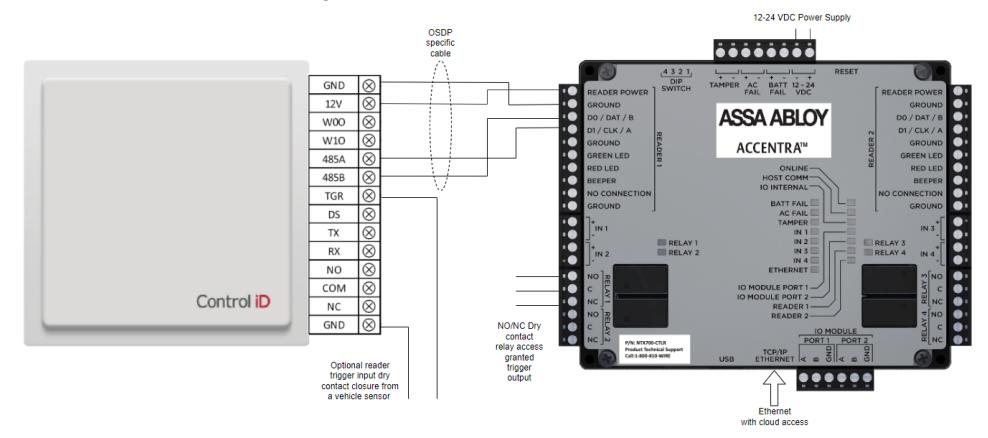
|
Label on
Controller Connector Block |
Reader
Terminal Block Connections |
|---|---|
| READER POWER | 12V |
| GROUND | GND |
| D0/DAT/B | 485B |
| D1/CLK/A | 485A |
| N/A |
TGR (optional
from reader to sensor) |
ACCENTRA ASSA ABLOY
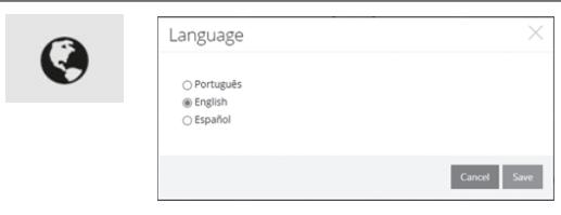
- 14. Change the language by clicking on the globe icon in the top row on the screen. Select the desired language from the pop-up window.
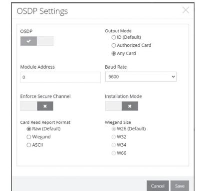
- 15. Click the OSDP Settings icon in the top row on the screen. In the OSDP Settings pop-up, click the box in the upper left corner to enable OSDP (green checkmark). Then select "Any Card" under Output Mode.
UHF Reader
Continuous
Inhibition
Optional Parking Reader Configuration Settings:
The optional settings affect how the reader operations based on requirements.
Click the UHF Reader icon in the second row on the screen
If a trigger/vehicle sensor device is being used, change the Operation mode from Continuous to Trigger. Note that in most cases this will only be used when a sensor is in use
Then set the contacts to NC. The contact needs to close for the trigger to function.
Set the Trigger Timeout time (in milliseconds) to set how long the reader is active when triggered.
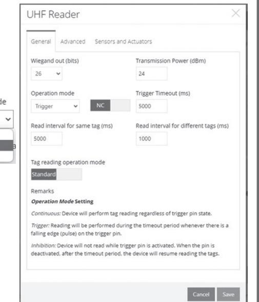
Set the Reader interval for same tag (in milliseconds) to a time that prevents the same credential from being read too frequently (anti-tailgating).
Set the Read interval for different tags (in milliseconds) to a time before the reader can read a different tag.
General Controller Settings
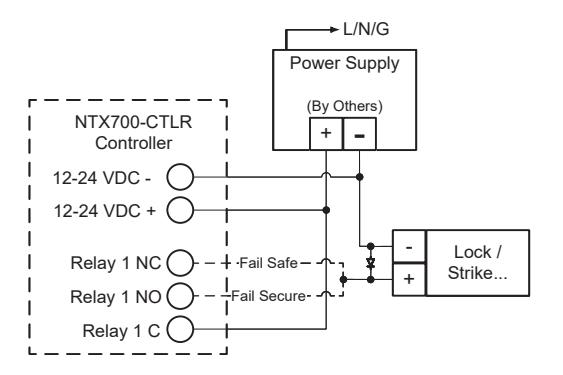
Example Connection of Electric Lock via Relay:
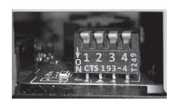
DIP Switch Configuration:
· All switches come factory defaulted to OFF
| DIP Switch | Setting | |
|---|---|---|
| 1 - 4 | n/a Should be OFF | |
USB Connector:
The controller offers a direct terminal interface by connecting a computer to the USB micro port. The computer will see the port as a virtual serial device that can be connected to any terminal program. Examples include minicom or screen on a *NIX OS or Putty on Windows. Once connected, a terminal, directly interfacing the controller's OS, will be presented.

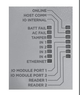
Status LEDs:
LEDs as shown to the most right in the figure indicate normal system activity. They have the following functions:
| Label | Function | |
|---|---|---|
| ONLINE | Flashes in normal operation | |
| IO INTERNAL | Flashes in normal operation | |
| ETHERNET | Network activity | |
Not Shorted
Shorted
Request to Exit (REX):
- IN 2 + / IN 2 -
- Shorted = REX
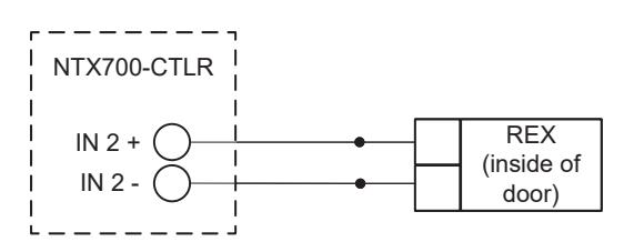
When the door/DPS is opened with the REX in a Non-Shorted state, a DOOR FORCED OPEN notification is sent. If the REX is Shorted prior to the door/DPS opening, then a DOOR OPEN MANUALLY notification is sent.
Door Position Sensor (DPS):
- IN 1 + / IN 1 -
- Shorted = Door Closed
- Not Shorted = Door Open
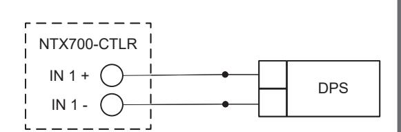
DPS function must be activated (once) after a controller configuration for the function to report DOOR OPEN or CLOSED state. To activate the DPS function, connect DPS and have door in a closed state. If the door stays open for the defined Door Held time (default = 30 seconds), a DOOR HELD notification is sent. The Door Held time is configurable.
Remote Unlock:
• AC FAIL +/ AC FAIL - This is being repurposed as remote unlock input to the controller.
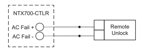
A momentary Normally Open (NO) switch can be connected to the I/O Connector. When pressed, the relay Shorts to activate a single time to unlock the door. The Default Relock time is 5 seconds. Holding the switch will not continue to keep the door in an unlocked state. The Default Relock time is not configurable.

5. Technical Specifications Updater (con't):
Controller (NTX700-CTLR):
| Dimensions |
6.46" x 5.51" x 1.02"
(164mm x 140mm x 26mm) |
|---|---|
| Input Voltage | 12VDC to 24VDC +/- 10% |
| Maximum Input Current | 1.9 A, 550mA excluding readers and USB |
| Memory & Clock Backup Battery | 3 volt Lithium, type CR2032 |
| Host Communication |
Ethernet: 10Base T//100Base-TX
Micro-USB port (2.0) |
| Output |
Four relays, Form-C with dry contacts:
Normally open contact (NO): 5 A @ 30VDC resistive Normally closed contact (NC): 3 A @ 30VDC resistive |
| Reader Power | 12VDC +/- 10%, 500 mA maximum each reader |
| Data Inputs | TTL compatible or 2-wire RS-485 |
| Operating Temperature | 32°F (0°C) to 158°F (70°C) |
| Warranty | 1 year |
| Certifications | Certified FCC Part 15 |
Updater:
| Base Part Number | NTX61x | NTX64x |
|---|---|---|
| Typical Read Range | iCLASS Seos: Contact | iCLASS Seos: Contact |
| Mounting |
Mini-Mullion Size;
physically HID's smallest iCLASS readers and are ideally suited for mullion mounted door installations, U.S. single-gang J-box (with mud ring) or any flat surface |
Wall Switch Size;
designed to mount and cover single gang switch boxes primarily used in the Americas and includes a slotted mounting plate for European and Asian back box spacing |
| Dimensions |
1.9" x 4.1" . 0.9"
4.8cm x 10.3cm x 2.3cm |
3.3" x 4.8" . 1.0"
8.4cm x 12.2cm x 2.4cm |
| Product Weight (Pigtail) | 3.9 oz (113g) | 7.7 oz (220g) |
| Base Part Number | NTX61x | NTX64x |
|---|---|---|
| Product Weight (Terminal Strip) | 2.9 oz (84g) | 7.5 oz (215g) |
| UL Ref Number | R10E | E40E |
| Operating Voltage Range | 5-16 VDC | |
| Color | Black | |
|
Current Draw - Standard Power
Mode2 |
60mA @ 16V | |
|
Peak Current Draw - Standard
Power |
200mA @ 16V | |
| Operating Temperature | -31° to 150°F (-35° to 65°C) | |
| Operating Humidity | 5% to 95% relative humidity non-condensing | |
| Environmental Rating |
Indoor/Outdoor IP55; IP65 if installed with optional
gasket |
|
| Transmit Frequency | 13.56 MHz | |
| 13.56 MHz Card Compatibility | Secure Identity Object™ (SIO) on iCLASS Seos | |
|
2.4 GHz Mobile Card
Compatibility |
Secure Identity Object™ (SIO) on mobile IDs | |
| Communications | Open Supervised Device Protocol (OSDP) via RS485 | |
| Panel Connection | Pigtail or Terminal Strip | |
| Certifications |
UL294/cUL (US), FCC Certification (US), IC (Canada),
CE (EU) |
|
|
Cryto Processor Hardware
Common Criteria Rating |
EAL5+ | |
| Housing Material | UL94 Polycarbonate | |
|
Manufactured with % of recycled
content (Pigtail) |
10.5% | |
|
Manufactured with % of recycled
content (Terminal Strip) |
11.0% | |
| Warranty | Limited Lifetime | |

Parking Reader:
| Base Part Number | NTX912 | NTX942 | |
|---|---|---|---|
| Typical Read Range (UHF) | up to 12m | up to 15m | |
| Mounting |
Adjustable mounting
clamp for pole installation allows for height and read angle adjustments |
Adjustable mounting
clamp for pole installation allows for height and read angle adjustments |
|
| Dimensions |
10.83" x 10.83" x 2.76"
275mm x 275mm x 70mm |
16.54" x 16.54" x 2.36"
420mm x 420mm x 60mm |
|
| Product Weight | 2.82lb (1280g) | 5.0lb (2270g) | |
| Power Input |
External 12V power supply
(not included) |
External 12V power supply
(not included) |
|
| Total Consumption | 3.5W (300mA) rated | 3.5W (300mA) rated | |
| Communication: | |||
| Ethernet | 1 native 10/100Mbps Ethernet port | ||
| RS-485 | 1 native RS-485 port with 120 Ohm termination | ||
| RS-232 | 1 native RS232 port | ||
| Output Relay | 1 relay up to 30VAC / 5A | ||
| Wiegand Output | 1 native output | ||
| Additional Inputs | Trigger and Door Sensor Inputs | ||
| Operating Temperature | -4°F to 104°F (-20°C to 40°C) | ||
| Operating Humidity | 0 to 95% non-condensing | ||
| Environmental Rating | IP65 | ||
| Certifications | FCC Certification (US) | ||
If you are an ASSA ABLOY ACCENTRA Certified Integrator and have any questions regarding these instructions, please contact 1-800-810-9473 or techsupport.accentra@ assaabloy.com for details. If you are a system user, please contact your Certified Integrator with any questions.

Phone
1-800-810-9473
Customer Service Email
customerservice.accentra@assaabloy.com
Technical Product Support Email
techsupport.accentra@assaabloy.com
Order Entry Email
orders.accentra@assaabloy.com
Fax
1-800-338-0965
Website
www.accentra-assaabloy.com
Contact Us
U.S.A.
ASSA ABLOY ACCENTRA
Address: 225 Episcopal Road Berlin, CT 06037-4004 Tel: 1-800-438-1951 Fax: 1-800-338-0965 accentra-assaabloy.com
Canada:
ASSA ABLOY Door Security Solutions Canada
Address: 160 Four Valley Drive Vaughan, Ontario L4K 4T9 Tel: 1-800-461-3007 Fax: 1-800-461-8989 assaabloydss.ca
International:
ASSA ABLOY Americas International
Tel: 1-905-821-7775 Fax: 1-905-821-1429 assaabloyai.com
THE ASSA ABLOY GROUP is the world´s leading manufacturer and supplier of locking solutions, dedicated to satisfying end-user needs for security, safety and convenience.
Copyright © 2020-2024, ASSA ABLOY ACCENTRA™ Access and Egress Hardware Group, Inc. All rights reserved. Reproduction in whole or in part without the express written permission of ASSA ABLOY Access and Egress Hardware Group, Inc. is prohibited. Patent pending and/or patent www.assaabloydss.com/patents.