ASSA ABLOY ACCENTRA Motorized Electric Latch Retraction (MELR) for 8800 Series Mortise Locks Installation Instru…_80-9086-0060-010
Open the original PDF document
View PDF8800 Series Mortise Lockset Motorized Electric Latch Retraction (MELR)

Installation Instructions
Tools Required

IMPORTANT!
The accuracy of the door preparation is critical for the proper functioning and security of this mortise lock. Misalignment can cause premature wear and tear and a lessening of security.
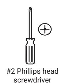
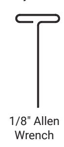

Wrench Hole saws (See template. Required sizes depend on application.)
1. Mark and Drill Door
- A. Mark horizontal line across face of door. 39-15/16" (101cm) is the usual lever height above the fi nished fl oor.
- B. Align the provided template center on the horizontal line. Before drilling, verify that the backset, door handing, and side of the door correspond to the side of the template being used.
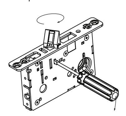
2. Verify Handing
If required, adjust the handing for the lockbody.
Handing the Latchbolt
- A. Insert fl at blade screwdriver into cover slot.
- B. Pull back on screwdriver until latchbolt extends past base front and rotate the head to the desired position.
Handing the Hubs
- A. Locate RED MARK on locking piece.
- B. Push toggle button slide away from "square spindle hole."
- C. With blade screw driver push RED MARK on slide nearest "square spindle hole."
- D. RED MARK indicates locked side.
39 15/16" (101cm)
Finished Floor

WARNING
This product can expose you to lead which is known to the state of California to cause cancer and birth defects or other reproductive harm. For more information go to www.P65warnings.ca.gov.

80-9086-0060-010 04/24 Attention Installer: Any retrofi t or other fi eld modifi cation to a fi re rated opening can potentially impact the fi re rating of the opening, and ASSA ABLOY makes no representations or warranties concerning what such impact may be in any specifi c situation. When retrofi tting any portion of an existing fi re-rated opening, or specifying and installing a new fi re-rated opening, please consult with a code specialist or local code offi cial (Authority Having Jurisdiction) to ensure compliance with all applicable codes and ratings.
For installation assistance contact 1-800-810-WIRE (9473) • www.accentra-assaabloy.com

Motorized Electric Latch Retraction (MELR) Installation Instructions
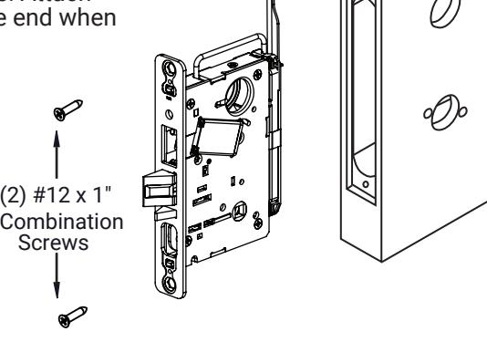
3. Install Lockbody
Important: Door must remain open during installation. Use door stop.
Connect lock harness with ElectroLynx® cable routed through door. Insert lockbody in door. Ensure the bevel of the latchbolt faces the strike plate. Attach with two #12 x 1" combination screws. Leave attaching screws loose until the end when all will be tightened securely.
4. Install Trim
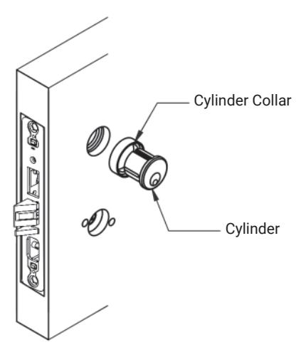
A. Install Cylinder (If applicable)
- 1. Insert cylinder through the cylinder collar, door and into lock.
- 2. Securely hand tighten cylinder set screw through the edge of the lock case.
NOTE: Do not use powered screw drivers to tighten cylinder set screw.
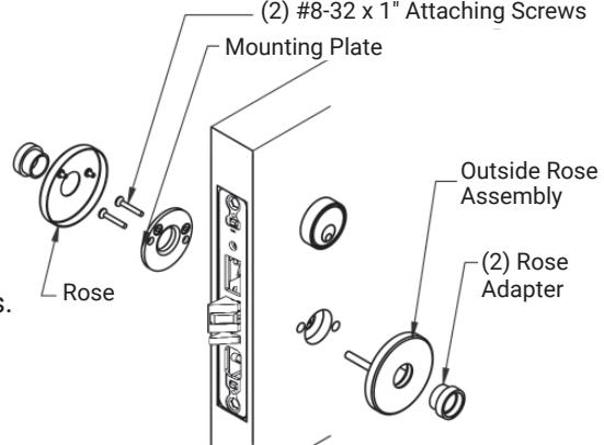
B. Rose Trim
- 1. Insert outside rose assemby (w/posts) through the door and into lock.
- 2. Align and fasten inside mounting plate with two #8-32 x 1" screws to posts.
- 3. Tighten screw securely.
- 4. Align and press rose posts to plastic bushings on mounting plate.
- 5. Go to Step 5.
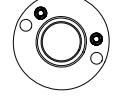
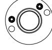
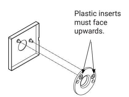
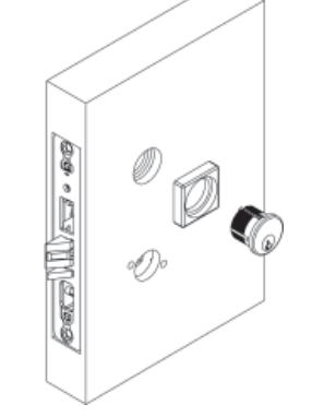
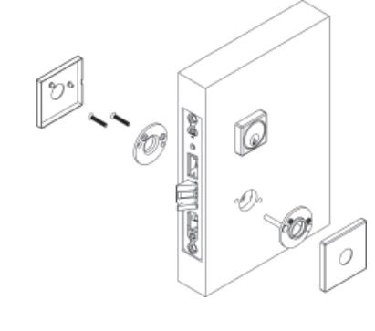
C. Square Rose Trim
1. Install cylinder with square collar and square rose trim, same as 4A and 4B.
The square rose and mounting plate needs to be oriented correctly during installation. Failure to do so causes roses that are crooked on the door, forcing the installer to remove and reinstall the parts. The proper orientation for the plastic rose-mounting inserts points in the upward direction. The rose is oriented with the slot facing the hinge side of the door.
Slot in trim must face towards the hinge side of door. Correct orientation shown.

80-9086-0060-010 04/24
For installation assistance contact 1-800-810-WIRE (9473) • www.accentra-assaabloy.com
Motorized Electric Latch Retraction (MELR)
Installation Instructions
ACCENTRA ASSA ABLOY
4. Install Trim, continued
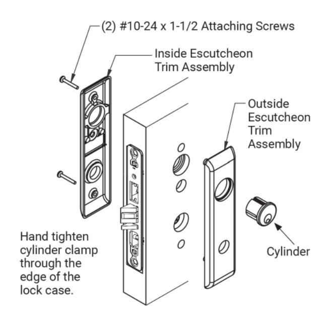
D. Escutcheon Trim - All types except SL
- Insert outside escutcheon assembly (w/posts) through the door and into lock.
- 2. Align and fasten inside escutcheon with #10-24 x 1-1/2" screws to posts.
- Align and fasten cylinder through escutcheon(s) and into lock body. Leave attaching screws loose until the end when all will be tightened securely.
- 4. Go to Step 5.
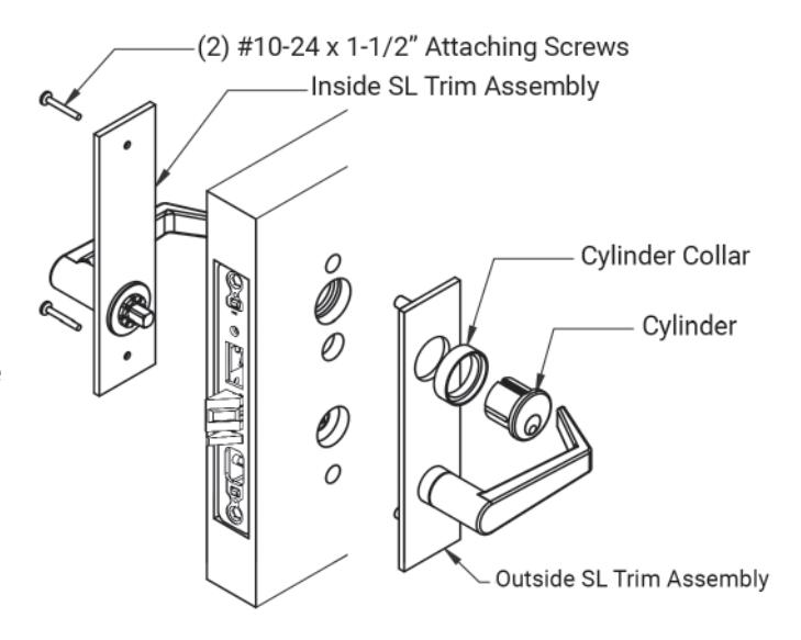
E. SL Escutcheon Trim
- Insert outside escutcheon assembly (with posts) through the door and into lock.
- Align and fasten inside escutcheon with #10-24 x 1-1/2" screws to posts.
- Align and fasten cylinder and cylinder collar through escutcheon(s) and into lock body.
5. Install Lever Assembly
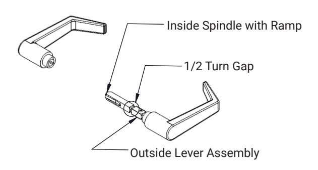
A. Prepare Lever Assembly - Not including SL Trim
1. Remove from packaging and remove inside lever.
2. Unscrew the inside spindle from the outside lever assembly 1/2 turn and align the ramp in the horizontal position before inserting into the lock.
80-9086-0060-010 04/24

Motorized Electric Latch Retraction (MELR) Installation Instructions
5. Install Lever Assembly, continued
B. Install Lever Assembly on Rose and Escutcheon Trims - Not including SL Trim
- 1. Insert outside lever assembly through the rose or escutcheon trim and through the lockbody.
- 2. Insert inside lever onto the outside lever assembly spindle and tighten inside lever set screw.
Set Screw Inside Lever (2) Plastic Bushing Outside Lever Assembly
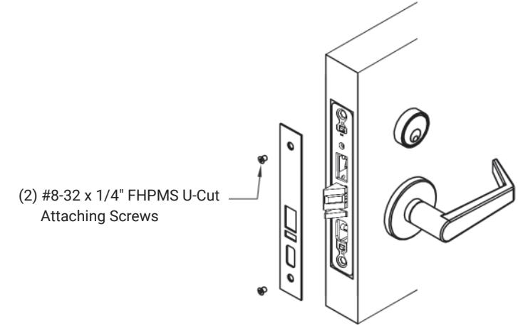
6. Install Armor Front
1. Align armor front to front of lockbody and attach screws.
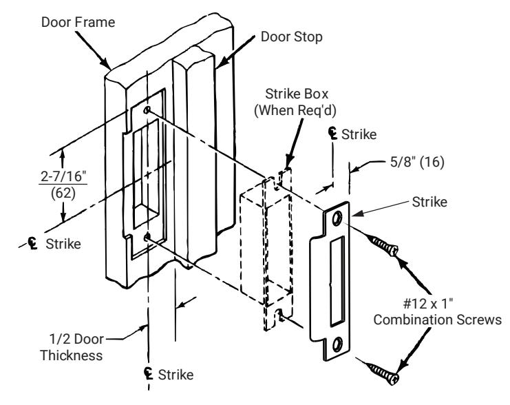
7. Install Strike
1. Attach strike to jamb using #12 x 1" combination screws.
80-9086-0060-010 04/24
For installation assistance contact 1-800-810-WIRE (9473) • www.accentra-assaabloy.com
Motorized Electric Latch Retraction (MELR)
Installation Instructions

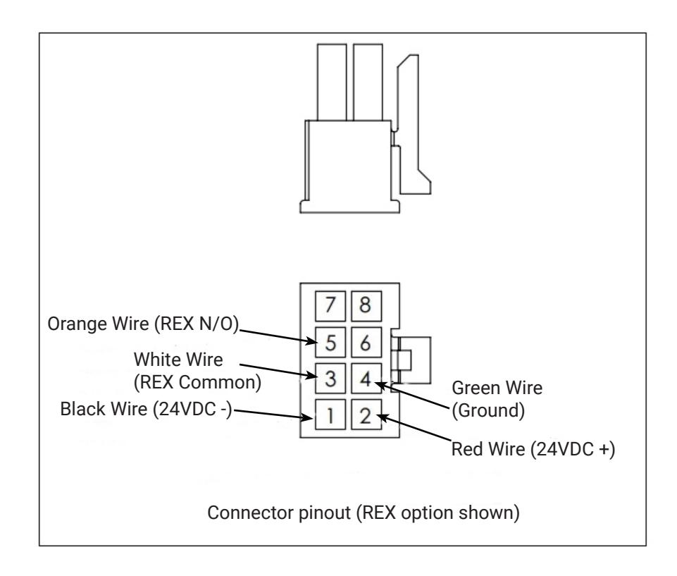
8. Lock Schematic

Check polarity. Verify + (red) wire. For assistance, call 800-810-WIRE.
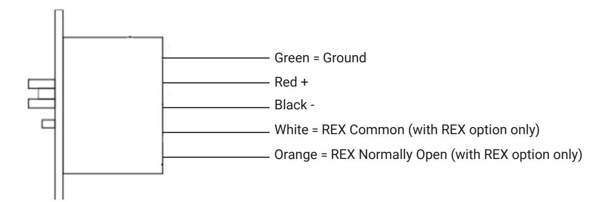
Electrical Specifi cations
- Voltage: 24 VDC (+10% / 15%)
- Operating Current: 700mA
- Hold Current: 50mA
Notes:
- The minimum permissible wire size to be used shall not be less than 26 AWG.
- Shall be powered by a UL294 and ULC-60839 Class 2 Power Limited power suplly or Listed Control units.
- Wireing methods shall be in accordance with the National Electrical Code (ANSI/NFPA70), CSA 22.1, Canadian Electrical Code (CEC), Part I, Safety Standard for Electrical Installations, local codes and the authorities having jurisdiction.
80-9086-0060-010 04/24

Motorized Electric Latch Retraction (MELR) Installation Instructions
9. Wiring Diagram - Simple Latch Retraction
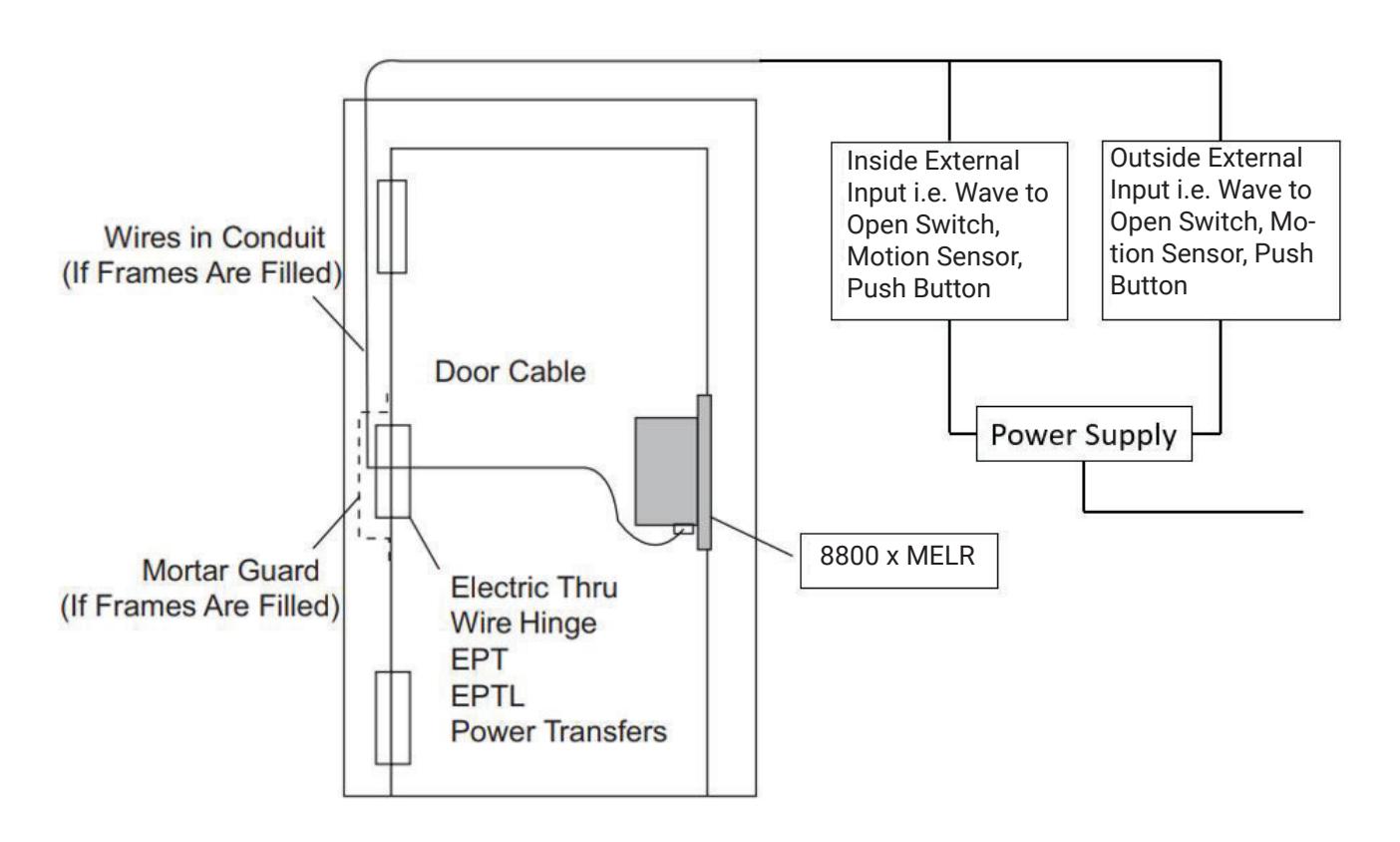
Operation: Activating inside or outside external input will retract latchbolt. Latchbolt remains retracted until power off.
Motorized Electric Latch Retraction (MELR)
Installation Instructions

10. Wiring Diagram - Automatic Door
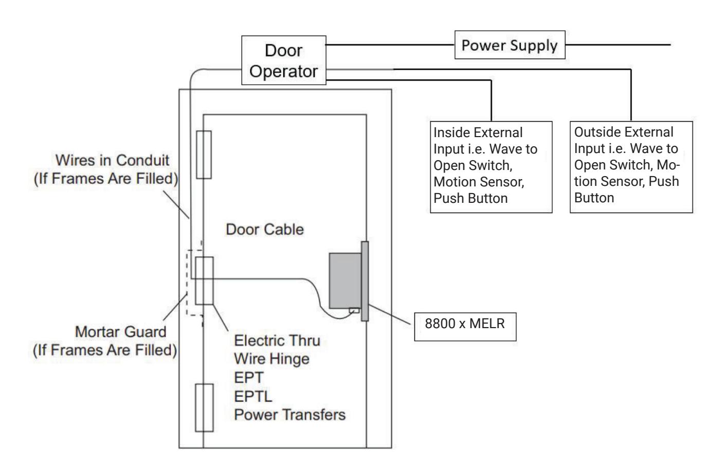
Operation: Activating inside or outside external input will retract latchbolt and door operator will open the door. Latchbolt remains retracted until power off.

11. Wiring Diagram - Restroom Privacy
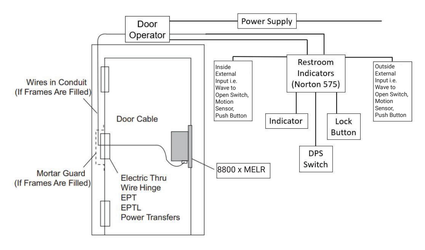
Operation: Activating inside or outside external input will retract latchbolt and door operator will open the door, unless outside external input is disabled by lock button. Indicator will illuminate when outside external input is disabled. Latchbolt remains retracted until power off.