ASSA ABLOY ACCENTRA Master (PTDO) or Support (PTO) Units, Push or Pull Side Installation_80-9344-0716-010
Open the original PDF document
View PDF

CAUTION
An incorrectly installed or improperly adjusted door closer can cause property damage or personal injury. These instructions should be followed to avoid the possibility of misapplication or misadjustment.
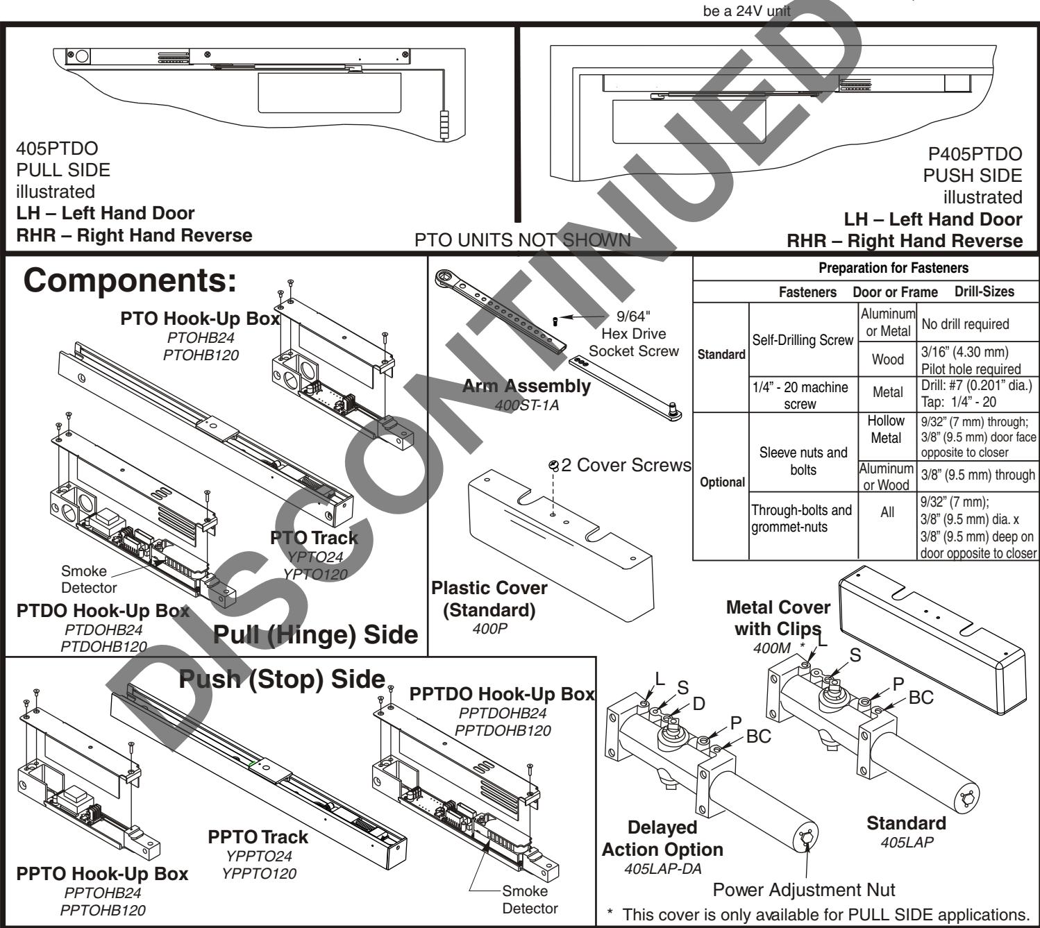
Power Track® Series Master Unit – PTDO (with detector) Support Unit - PTO (without detector)
Models
Hinge (Pull) Side of Stop (Push) Side of Door Application Door Application
405PTDO P405PTDO 405PTO P405PTO
NOTES: - For wiring of PTDO models, see "PowerTrack®" "Wiring Instructions" No. 80-9342-0902-021 (01-09)
- When used with a PTDO model, PTO unit must
Installation Instructions
80-9344-0716-010 (07-10)
Combination Door Closer-Holder and Releasing Device WITH and WITHOUT Integral Smoke Detector
NOTE:
- For special applications a separate door and frame preparation template is packed with these instructions.
- Use this instruction sheet for installation sequence and closer adjustments only.
- Use of an auxiliary door stop is always recommended.
- Unit must be mounted on interior of building in dry environment, maximum humidity of 95%.
- See NFPA70 for wiring requirements and NFPA72 for alarm system requirements.

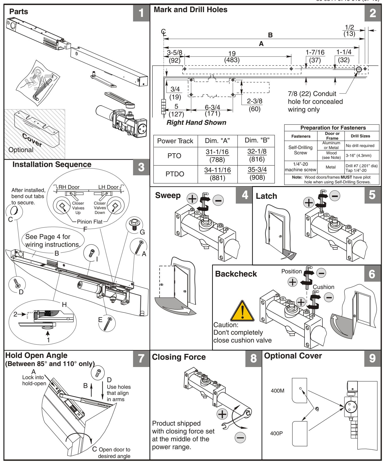
405PTO/405PTDO Series
Hinge (Pull) Side Application
80-9344-0716-010 (07-10)
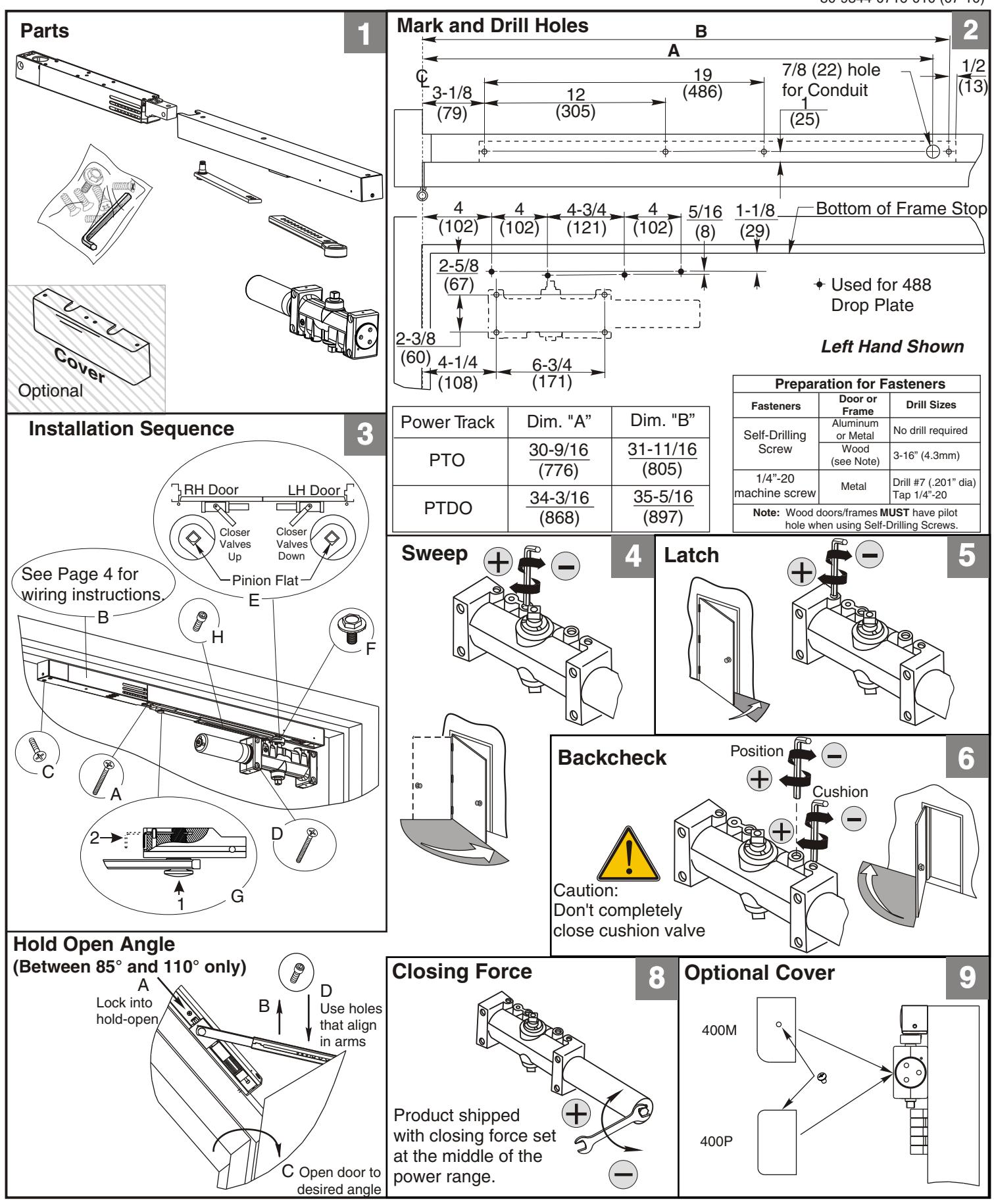
P405PTO/P405PTDO Series
Stop (Push) Side Application
80-9344-0716-010 (07-10)
PTO Support Unit Wiring Diagram (24VAC/DC Input)
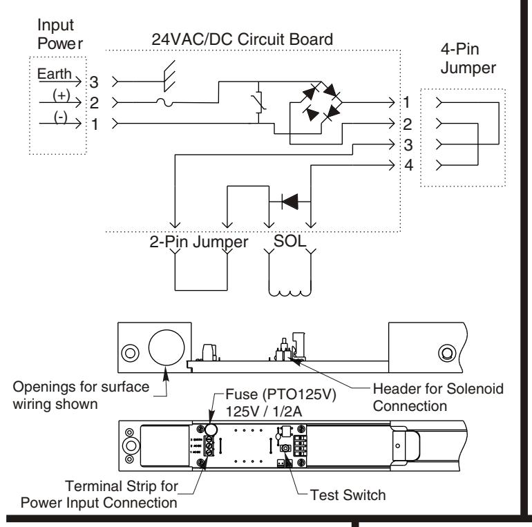
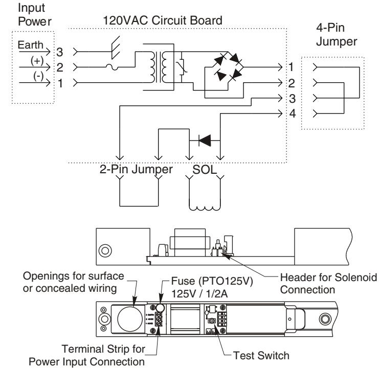
PTO Support Unit Wiring Diagram (120VAC Input)
(Do not use a 120VAC PTO unit when power is supplied from a PTDO unit)
For PTDO Models:
Refer to Wiring Instructions No. 80-9342-0902-021 (01-09) for making wiring connections.
| ELECTRICAL DATA | ||||
|---|---|---|---|---|
| 120VAC | 24VAC | 24VDC | Detector | |
| Voltage |
120V 132V Max
102V Min |
24V 26.4V Max
20.4V Min |
24V 26.4V Max
20.4V Min |
24V 26.4V Max
20.4V Min |
| Current | .036 Amps | .059 Amps | .074 Amps | 0.034 Amps |
NOTES:
- Maximum wire size is 14AWG.
- All wiring and connections use standard wiring practice conforming with local wiring codes.
IMPORTANT:
After making all wiring connections:
- Turn power to unit "ON". (On Master (PTDO) unit only, red LED should illuminate once every 15 sec.).
- Open door to hold-open position. Manually pull door out of hold-open and release...door should close. If arm does not release from hold-open, increase the releasing force by turning the screw accessible thru the end cap of the track using the 9/64" hex wrench provided.
- Again, open door to the hold-open position. Depress "Test Switch" button on the hook-up board (accessible through cover)...door should close. If arm does not release, see previous step.
Installation of Cover:
- Plastic Cover (400P): Slide cover insert into the un-used cutout in cover. Install cover using screws provided.
- •Metal Cover (400M): Fasten cover to mounting clips with screws provided.
Yale® and PowerTrack® are registered trademarks of Yale Security Inc., an ASSA ABLOY Group company. These materials are protected under U.S. Copyright laws. Copyright @ 2009, 2010, Yale Security Inc., ASSA ABLOY Group company. All rights reserved. Reproduction in whole or in part without the express written permission of Yale Security Inc. is prohibited.