ASSA ABLOY ACCENTRA KeyMark Protected Keyway Cylinder Service Manual_42250
Open the original PDF document
View PDF

KeyMark®
Protected Keyway Cylinder Service Manual

This product can expose you to lead which is known to the state of California to cause cancer and birth defects or other reproductive harm. For more information go to www.P65warnings.ca.gov.

Table Of Contents
| The Security Leg® 2 | |
|---|---|
| Cylinder Exploded Views and Part Numbers 3-6 | |
| Parts Breakdown 7 | |
| Pin Specifications 8 | |
| Pins and Pin Kits 9 | |
| Key Bitting Specifications 10 | |
| Key Cutting 11 | |
| Key Cutting Log 12 | |
| Combinating Cylinders 13 | |
| Combinating Worksheets 14-17 | |
| Master Keying 18-19 |
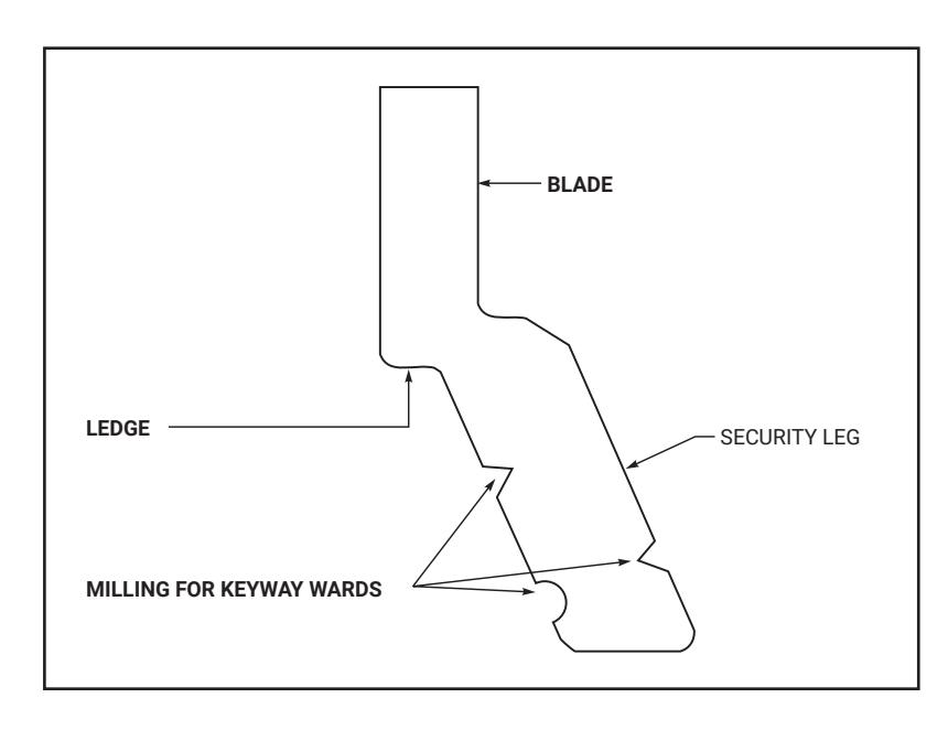
Protected Keyway
The Security Leg
The KeyMark keyway has three distinct components: an upper portion or blade, a middle ledge, and a unique, lower angled portion or leg which exits the plug at an angle. This Security Leg keyway offers these advantages:
- 1. Keyway differentiation by angle;
- 2. Increased pick resistance;
- 3. Prevents other manufacturers' or other angle users' keys from entering the cylinder;
- 4. A unique and strong key with true key control;
- 5. A key blank of added thickness for extra strength and durability;
- 6. Prevents duplication of keys on standard key machines.
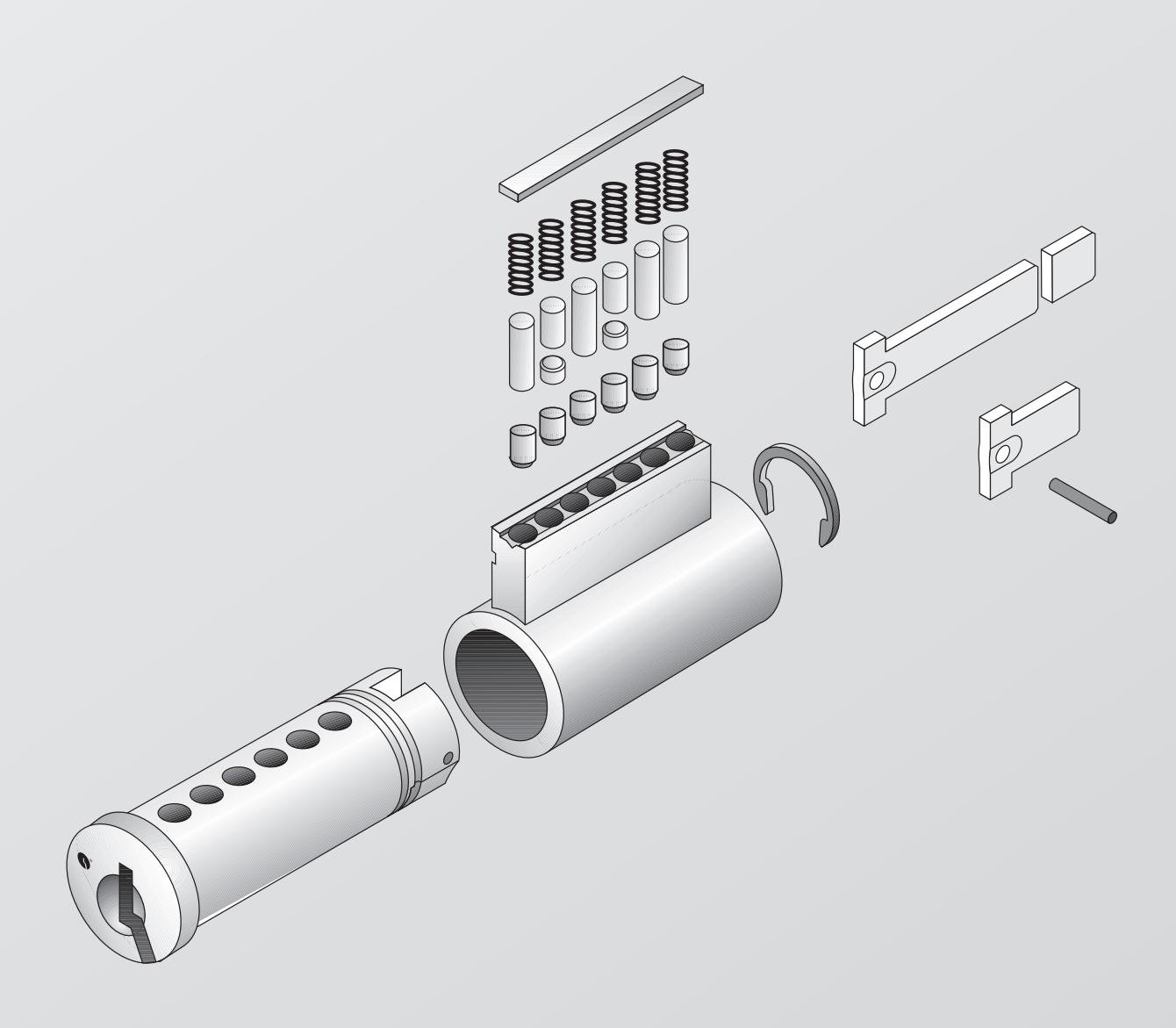
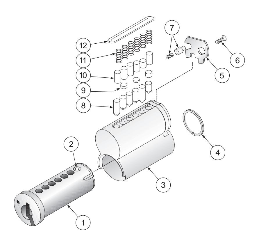
Mortise/Rim Cylinders
| Item | Description | Qty. |
Mortise
Model No. |
Rim
Model No. |
Remarks |
|---|---|---|---|---|---|
| 1 | Mortise Plug511" | 1 | K150 | NA | Length, keyway and finish required |
| 2 | Shell | 1 | K151 | K351 | Finish required |
| 3 | Cam | 1 | KC1 | NA | KC1 standard, refer to page 7 for options |
| 4 | Cam Washer | 1 | KP1 | NA | |
| 5 | Cam Screw | 2 | KP2 | NA | |
| 6 | Bottom Pins | * | * | * | Refer to page 9 for options |
| 7 | Top Pins (Master) | * | * | * | Refer to page 9 for options |
| 8 | Top Pins (Driver) | * | * | * | Refer to page 9 for options |
| 9 | Tumbler Springs | 6 or 7 | K730 | K730 | |
| 10 | Set Screws | 6 or 7 | K736 | K736 | |
| 11 | Plug Retainer | 1 | NA | K739 | |
| 12 | Rim Plug511" Plug Diameter | 1 | NA | K350 | Finish & keyway required |
| 13 | Collar | 1 | NA | KP4 | Finish required |
| 14 | Mounting Plate | 1 | NA | Part | 34-0010-1015-059 |
| 15 | Mounting Screws | 2 | NA | Part | 34-2311-8738-048 |
| 16 | Tailpiece (Break-off) | 1 | NA | KT1 | Includes tailpiece retainer |
| 17 | Tailpiece Retainer | 1 | NA | * | Included with tailpiece |
* See remarks.

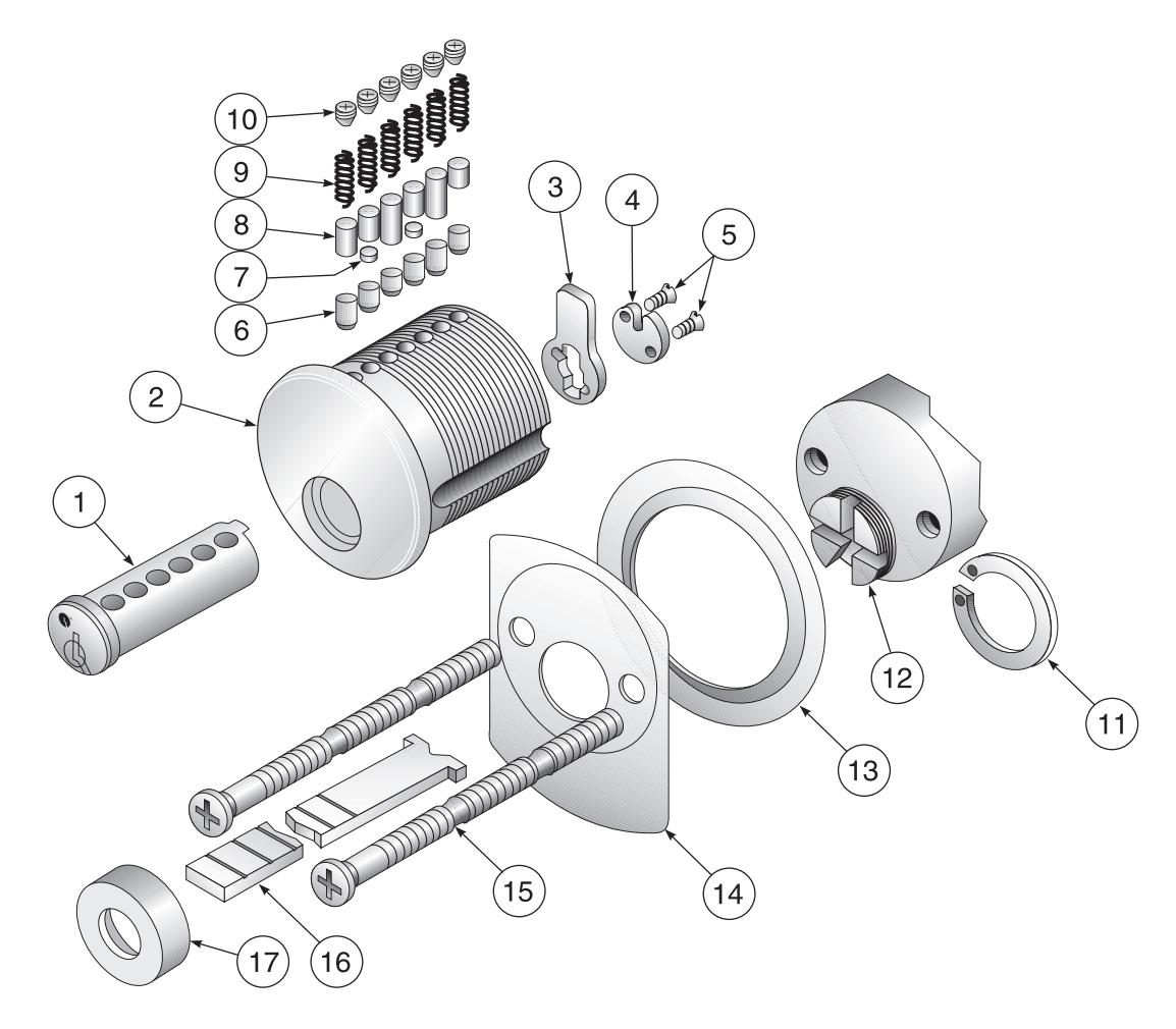
Small Format Interchangeable Core
| ITEM | Description | Qty. | Catalog No. | Remarks |
|---|---|---|---|---|
| 1 | Shell | 1 | ** | Not available separately |
| 2 | Pin Ejector Holes | 6 or 7 | * | For location information only |
| 3 | Control Sleeve | 1 | ** | Not available separately |
| 4 | Control Lug | 1 | ** | Not available separately |
| 5 | Plug434" Plug Diameter | 1 | ** | Not available separately |
| 6 | Rivet Posts | * | ** | Not available separately |
| 7 | Key Stop Back Plate | 1 | ** | Not available separately |
| 8 | Bottom Pins | * | * | Refer to page 9 for options |
| 9 | Top Pins (Master) | * | * | Refer to page 9 for options |
| 10 | Top Pins (Build-up) | * | * | Refer to page 9 for options |
| 11 | Top Pins (Driver) | * | * | Refer to page 9 for options |
| 12 | Tumbler Springs | 6 or 7 | K730 | |
| 13 | Pin Chamber Caps | 6 or 7 | K731 |
* See remarks.
** Parts included in K600, not available ordered separately.
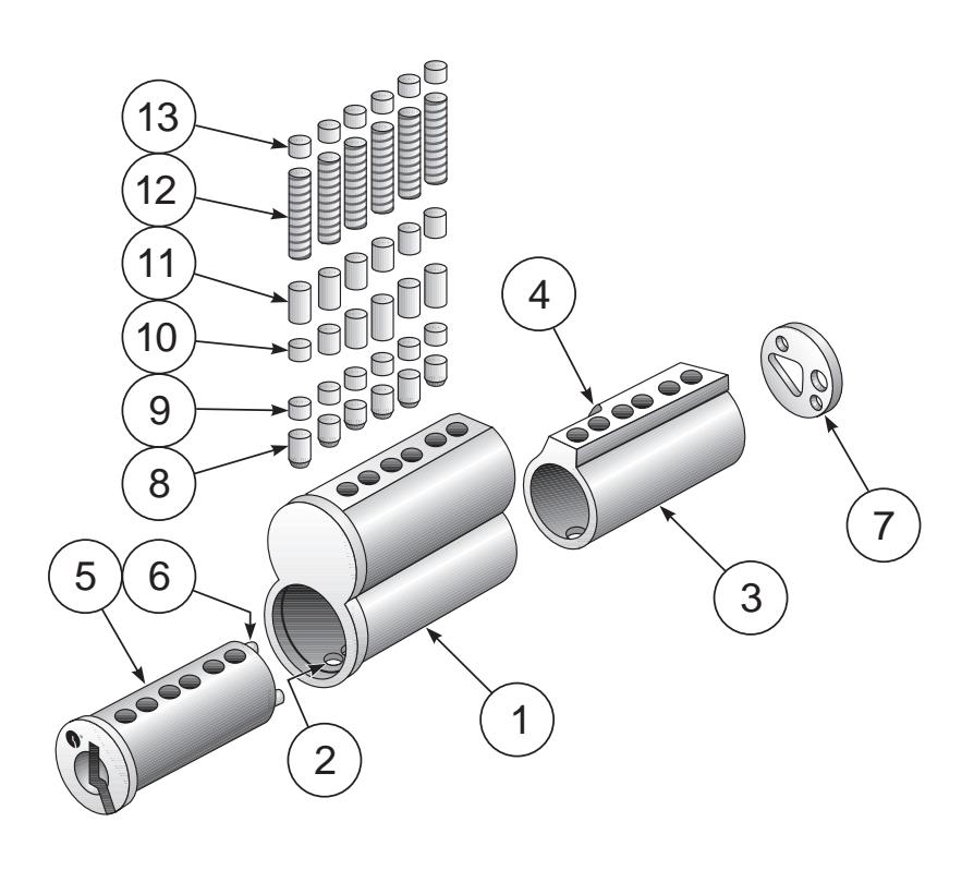
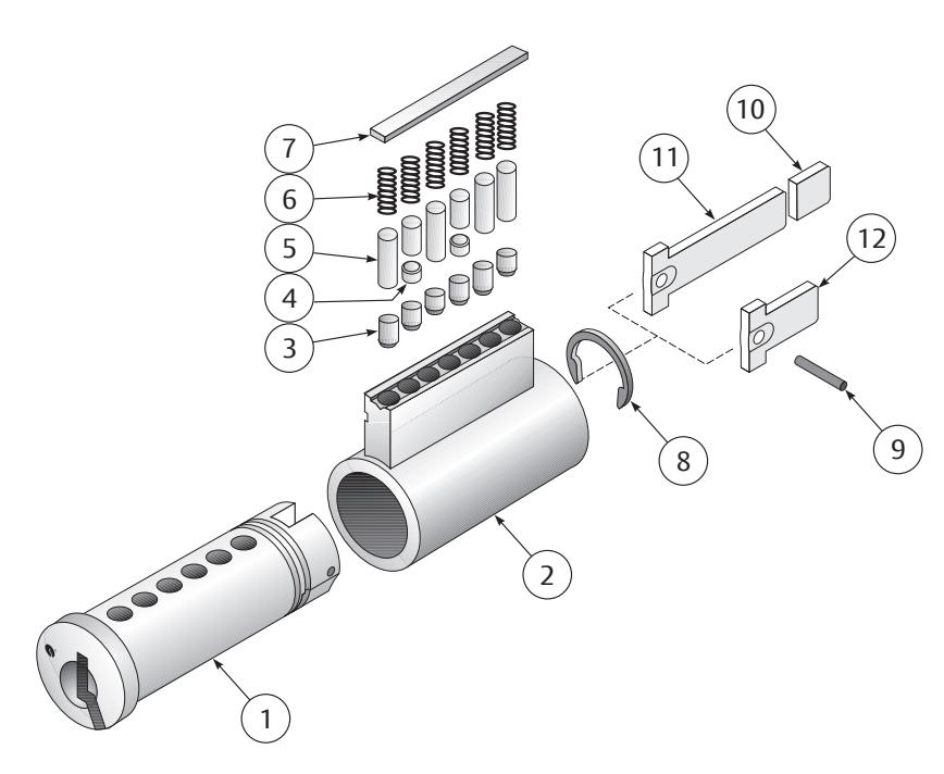
Large Format Interchangeable Core
| Item | Description | Qty. | Catalog No. | Remarks |
|---|---|---|---|---|
| 1 | Plug511" Plug Diameter | 1 | K850 | No. of pins, keyway and finish required |
| 2 | Control Pin and Spring | 1 | * | Staked in place |
| 3 | Shell | 1 | K851 |
No. of pins and finish required
Includes items 5, 6 and 7 |
| 4 | Plug Retainer | 1 | K740 | |
| 5 | Control Lug | 1 | * | Not available separately |
| 6 | Control Lug Retainer Screw | 1 | * | Not available separately |
| 7 | Control Lug Guide Pin and Spring | 1 | * | Not available separately |
| 8 | Bottom Pins | * | * | Refer to page 9 for options |
| 9 | Top Pins (Master) | * | * | Refer to page 9 for options |
| 10 | Top Pins (Driver) | * | * | Refer to page 9 for options |
| 11 | Tumbler Springs | 6 or 7 | K730 | |
| 12 | Spring Cover, 6-pin | 1 | K732 | |
| 12 | Spring Cover, 7-pin | 1 | K733 |
* See remarks.

Key-In-Knob/Lever Cylinders
| Item | Description | Qty. | Key-In-Knob Model No. | Key-in-Lever Model No. |
|---|---|---|---|---|
| 1 | Plug511" Plug | 1 | K450 | K450 |
| 2 | Shell | 1 | K451 | K451 |
| 3 | Bottom Pins | * | * | * |
| 4 | Top Pins (Master) | * | * | * |
| 5 | Top Pins (Driver) | * | * | * |
| 6 | Tumbler Springs | 6 or 7 | K730 | K730 |
| 7 | Spring Cover, 6-pin | 1 | K734 | K734 |
| 7 | Spring Cover, 7-pin | 1 | K735 | K735 |
| 8 | Plug Retainer | 1 | K741 | K741 |
| 9 | Roll Pin | 1 | NA | Part |
| 10 | Tailpiece | 1 | NA | KT2 |
| 11 | Tailpiece | 1 | NA | KT7 |
| 12 | Tailpiece | 1 | NA | KT3 |
Note: Tailpiece length varies by function and application.
Auxiliary Cylinders (Not Illustrated)
The items in the chart at right are specific to auxiliary cylinders. Item numbers 2 through 8 above are also included.
| Description | Qty. | Model No. | Remarks |
|---|---|---|---|
| Plug | 1 | K251 | Used with K200 |
| Tailpiece | 1 | KT4 | Used with K200 |
| Tailpiece | 1 | KT6 | Used with K290 only |
| Cylinder Collar | 1 | Part | 14-3511-1013-048 |
| Lazy Cam | 1 | Part | 14-3511-6102-082 |
| D-Ring | 1 | Part | 14-3511-1014-048 |
Note: Tailpiece length varies by function and application.
* See remarks.

Parts Breakdown
| Cylinder Parts | |||||
|---|---|---|---|---|---|
| Number | Description | Used With | Remarks | ||
| K730 | Tumbler Springs | All types | |||
| K731 | Pin Chamber Caps | K600 | SFIC | ||
| K732 | Spring Cover, 6-pin | K800 | LFIC | ||
| K733 | Spring Cover, 7-pin | K800 | LFIC | ||
| K734 | Spring Cover, 6-pin | K200/K400 | Aux./KIK/KIL | ||
| K735 | Spring Cover, 7-pin | K200/K400 | Aux./KIK/KIL | ||
| K736 | Set Screws | K100/K300 | Mortise/Rim | ||
| K739 | Plug Retainer | K300 | Rim | ||
| K740 | Plug Retainer | K800 | LFIC | ||
| K741 | Plug Retainer | K200/K400 | Aux./KIK/KIL | ||
|
Tailpieces
Length Varies by Function and Application |
|||||
|---|---|---|---|---|---|
| Number | Used With | Remarks | |||
| KT1 | K300/K840 | Rim/LFIC Rim | |||
| KT2 | K402 | 6-pin KIL | |||
| KT3 | K404 | KIL | |||
| KT4 | K200 | Auxiliary | |||
| KT5 | K490 | Schlage® KIL Kit | |||
| KT8 | K202 |
6-Pin Interconnected
Lock |
|||
|
Plugs
Length, Keyway and Finish Required |
|||||
|---|---|---|---|---|---|
| Number | Used With | Remarks | |||
| K150 | K100 | Mortise | |||
| K250 | K200 | Auxiliary | |||
| K350 | K300 | Rim | |||
| K450 | K400 | KIK/KIL | |||
| K850 | K800 | LFIC | |||
| Cams | |||||
|---|---|---|---|---|---|
| Number | Reference | ||||
| KC1 | 2160 | ||||
| KC2 | 2130 | ||||
| KC3 | 1161/Schlage Straight | ||||
| KC4 | 1160 | ||||
| KC5 | 1161 (AR) | ||||
| KC6 | 1161G (Key Switch) | ||||
| KC7 | Schlage Cloverleaf | ||||
| KC8 | Corbin Russwin Cloverleaf (A01) | ||||
| KC9 | Sargent® Straight | ||||
| KC10 | Affinity® | ||||
| Shells | |||||
|---|---|---|---|---|---|
| Length and Finish Required Where Applicable | |||||
| Number |
Used With
Remarks |
||||
| K151 | K100 | Mortise | |||
| K351 | K300 | Rim | |||
| K451 | K200/K400 | Aux./KIK/KIL | |||
| Cam Accessories | |||||
|---|---|---|---|---|---|
| Number | Description | ||||
| KP1 | Cam Washer | ||||
| KP2 | Cam Screws | ||||
Lubrication
KeyMark® cylinders are lubricated from the factory with a Teflon® lubrication. Cylinders should be lubricated periodically depending upon environmental conditions and usage. LAB Lube is the approved lubricant.
Caution: It is not recommended to lubricate cylinders with oil or to mix lubricants.

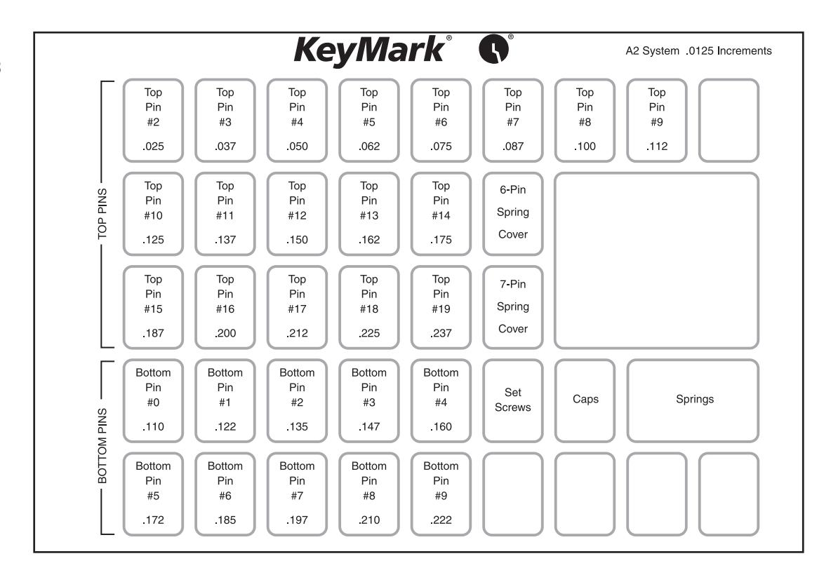
Pin Specifications
KeyMark® cylinders use selected top and bottom pins that are spool type for added security. While other manufacturers' pin kits can be used with KeyMark cylinders, the strict tolerances of pins and the added security from the spool pins are good reasons to use original KeyMark pins. Also, use of non-factory original pins can void the warranty.
To minimize the possibility of decoding the cylinder combination by reading the color of the pins, never use colored replacement pins.
Bottom pins are made of high-quality nickel silver. This distributes wear evenly between the key and the pins.
Top, build-up and master pins are made of brass.
- Pin increment is .0125"
- Pin diameter is .1085"
- Bottom pin tip flat is .015"
- Bottom pin crown is 45° x .008"; Top pin crown is 30° x .008"
- Total stack height is:
- .3975" for small format interchangeable core cylinders (23) .2375" for non-small format interchangeable core cylinders (19)
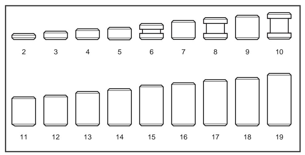
Master, Build-up and Top Pins
Bottom Pins
|
Master, Build-up &
Top Pins |
||||
|---|---|---|---|---|
| Size | Length |
Model
Number |
||
| 2 | .025" | K702 | ||
| 3 | .037" | K703 | ||
| 4 | .050" | K704 | ||
| 5 | .062" | K705 | ||
|
6
(Spool) |
.075" | K706 | ||
| 7 | .087" | K707 | ||
|
8
(Spool) |
.100" | K708 | ||
| 9 | .112" | K709 | ||
|
10
(Spool) |
.125" | K710 | ||
| 11 | .137" | K711 | ||
| 12 | .150" | K712 | ||
| 13 | .162" | K713 | ||
| 14 | .175" | K714 | ||
| 15 | .187" | K715 | ||
| 16 | .200" | K716 | ||
| 17 | .212" | K717 | ||
| 18 | .225" | K718 | ||
| 19 | .237" | K719 | ||
| Bottom Pins | ||||
|---|---|---|---|---|
| Size | Length |
Model
Number |
||
| 0 | .110" | K720 | ||
| 1 | .122" | K721 | ||
| 2 | .135" | K722 | ||
| 3 | .147" | K723 | ||
| 4 | .160" | K724 | ||
| 5 | .172" | K725 | ||
| 6 | .185" | K726 | ||
|
7
(Spool) |
.197" | K727 | ||
|
8
(Spool) |
.210" | K728 | ||
|
9
(Spool) |
.222" | K729 | ||

Pin Kits
K918
| Length | Bottom | Master Build-Up Top | Pin Kit Qty. |
|---|---|---|---|
| .025" | 2 | 100 | |
| .037" | 3 | 100 | |
| .050" | 4 | 100 | |
| .062" | 5 | 100 | |
| .075" | 6 | 100 | |
| .087" | 7 | 100 | |
| .100" | 8 | 100 | |
| .110" | 0 | 100 | |
| .112" | 9 | 100 | |
| .122" | 1 | 100 | |
| .125" | 10 | 100 | |
| .135" | 2 | 100 | |
| .137" | 11 | 100 | |
| .147" | 3 | 100 | |
| .150" | 12 | 100 | |
| .160" | 4 | 100 | |
| .162" | 13 | 100 | |
| .172" | 5 | 100 | |
| .175" | 14 | 100 | |
| .185" | 6 | 100 | |
| .187" | 15 | 100 | |
| .197" | 7 | 100 | |
| .200" | 16 | 100 | |
| .210" | 8 | 100 | |
| .212" | 17 | 100 | |
| .222" | 9 | 100 | |
| .225" | 18 | 100 | |
| .237" | 19 | 100 |
| Pin Kit Contents | |||||||||||
|---|---|---|---|---|---|---|---|---|---|---|---|
| Description |
Model
Number |
Pin Kit | Used With | ||||||||
| Tumbler Springs | K730 | 100 | All | ||||||||
| Pin Chamber Caps | K731 | 25 | K600 | ||||||||
| Spring Cover, 6-pin | K732 | 25 | K800 | ||||||||
| Spring Cover, 7-pin | K733 | 25 | K800 | ||||||||

Key Bitting Specifications
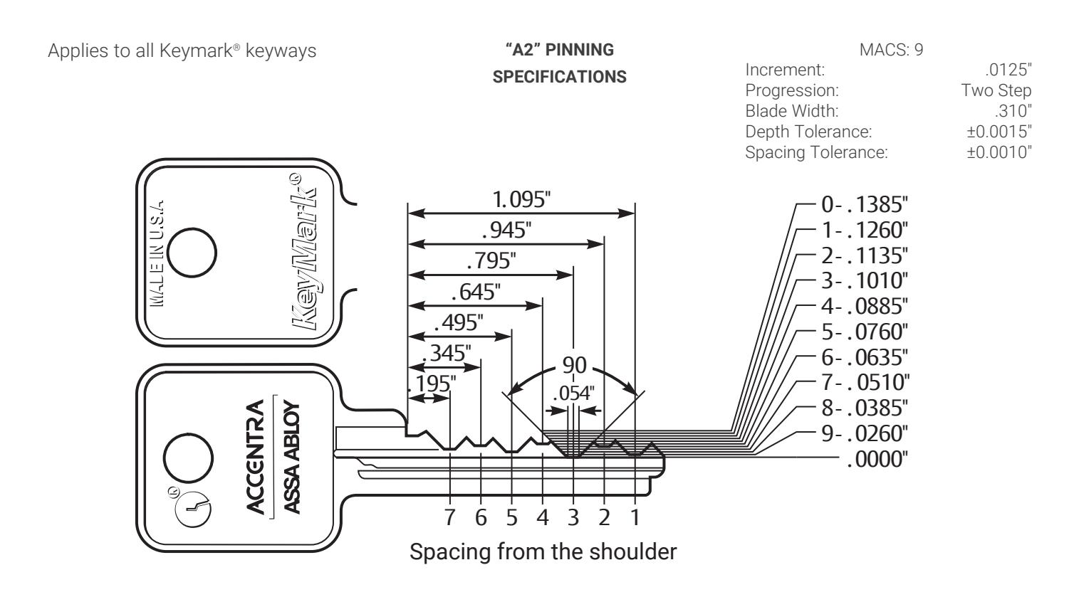
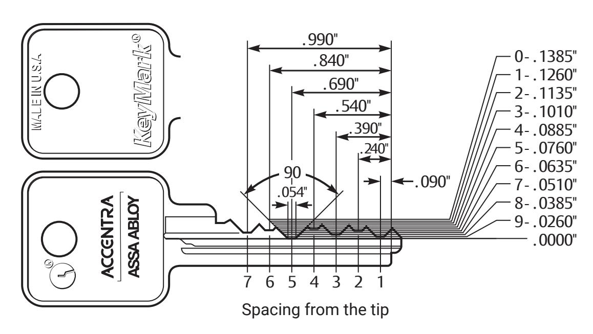
All Cuts Are Read and Written TIP to BOW
All depths are referenced from the offset or ledge of the key rather than from the bottom of the blade.

Key Cutting Log
| COMPANY/FACILITY NAME | BEGINNING INVENTORY | |||||||
|---|---|---|---|---|---|---|---|---|
| KEY BLANKS RECEIVED | ||||||||
| TOTAL CUT KEYS ISSUED | ||||||||
| KEYWAY | TOTAL MISCUT KEYS | |||||||
| SYSTEM REGISTRY | TOTAL ENDING INVENTORY | |||||||
| Date |
No. of
Cut Keys Issued |
No. of
Miscut |
Facility Issued To - As per NOA |
Zip
Code |
Key
Machine Operator |
Total
Blanks Used |
Balance
of Keys |
Notes |

Combinating Cylinders
Calculating the "A2" Pin Stack
Rules For Top Loading K600 (SFIC) Cylinders
For best results, pin the cylinder one chamber at a time.
- Pin the cylinder to the operating keys change key(s) and master keys(s) – using bottom and master pins
-
Pin the cylinder to the control key by inserting a "build-up pin" in each chamber. To determine the build-up pin numbers:
- Add 10 to each of the control key cuts. This is called the "control total";
- For each chamber, subtract the bottom pin and master pin total (plug total) from the control total;
- Use the resulting number as your build-up pin number.
- Load the top pin. To determine the top pin number, subtract the control total from 23. Reference the "Quick Subtraction Chart" for quick calculation (see page 15).
- The total stack height (the sum of all the pins) must equal 23.
- After all chambers have been pinned, insert the core into the capping block, load springs, and cap.
Rules For Top Loading K100/K200/K300/K400/K800 (Non-SFIC) Cylinders
For best results, pin the cylinder one chamber at a time.
- Pin the cylinder to the operating keys change key(s) and master keys(s) – using bottom and master pins
- Load the top pin. To determine the top pin number, subtract the bottom pin and master pin total (plug total) from 19. Reference the "Quick Subtraction Chart" for quick calculation (see page 17).
- The total stack height (the sum of all the pins) must equal 19.
- After all chambers have been pinned, insert the core/cylinder into the capping block, load springs, and cap.
SFIC • K600 Non-SFIC • All Other Types Plug Total = The Bottom Pin Plus The Master Pin Top Pin = 23 Minus The Control Total Top Pin = 19 Minus Plug Total Build-up Pin = The Control Total Minus The Plug Total Master Pin (if req.)= The Deep Minus The Shallowest Operating Cut Master Pin (if req.)= The Deep Minus The Shallowest Operating Cut Bottom Pin = The Shallowest Operating Cut Bottom Pin = The Shallowest Operating Cut
See page 14 & 15 for completed sample and blank combinating worksheets of SFIC cylinders. See page 16 & 17 for completed sample and blank combinating worksheets of Non-SFIC cylinders.

Combinating Worksheet: K600 (SFIC)
Completed Sample
| CHAMBERS | ||||||||||
|---|---|---|---|---|---|---|---|---|---|---|
| CALCULATION | TIP | BOW | ||||||||
| OPERATING KEYS | 1 | 2 | 3 | 4 | 5 | 6 | 7 | |||
| 01 | GGMK | Insert Bitting | — | — | — | — | — | — | — | |
| 02 | GMK A | Insert Bitting | 3 | 4 | 9 | 5 | 0 | 6 | ||
| 03 | MK AA | Insert Bitting | 5 | 2 | 9 | 5 | 0 | 6 | ||
| 04 | CK AA1 | Insert Bitting | 5 | 2 | 1 | 7 | 2 | 6 | ||
| P1» | 05 | Bottom Pin | [Shallowest Operating Cut] | 3 | 2 | 1 | 5 | 0 | 6 | |
| P2» | 06 | Master Pin |
[Deepest Minus Shallowest
Operating Cut] |
2 | 2 | 8 | 2 | 2 | X | |
| 07 | Plug Total | [Master Plus Bottom Total] | 5 | 4 | 9 | 7 | 2 | 6 | ||
| CONTROL KEY | ||||||||||
| C1 | Control Cut | Insert Bitting | 1 | 6 | 5 | 9 | 8 | 2 | ||
| C2 | Control Total | [Add 10 to C1] | 11 | 16 | 15 | 19 | 18 | 12 | ||
| BUILD-UP PIN | ||||||||||
| B1 | Control Total | [C2] | 11 | 16 | 15 | 19 | 18 | 12 | ||
| B2 | Plug Total | [07] | 5 | 4 | 9 | 7 | 2 | 6 | ||
| P3» | B3 | Build-up Pin | [Subtract B2 from B1] | 6 | 12 | 6 | 12 | 16 | 6 | |
| TOP PIN | ||||||||||
| T1 | Stack Height | [Pre-set] | 23 | 23 | 23 | 23 | 23 | 23 | 23 | |
| T2 | Control Total | [B1] | 11 | 16 | 15 | 19 | 18 | 12 | ||
| P4» | T3 | Top Pin | [Subtract T2 from T1] | 12 | 7 | 8 | 4 | 5 | 11 | |
| PINNING SET UP | ||||||||||
| (T3) | P4» | Top Pin | 12 | 7 | 8 | 4 | 5 | 11 | ||
| (B3) | P3» | Build-up Pin | 6 | 12 | 6 | 12 | 16 | 6 | ||
| (06) | P2» | Master Pin | 2 | 2 | 8 | 2 | 2 | X | ||
| (05) | P1» | Bottom Pin | 3 | 2 | 1 | 5 | 0 | 6 |
To verify: P1, P2, P3 & P4 in each chamber must add up to 23.

Combinating Worksheet: K600 (SFIC)
Blank Worksheet
| CHAMBERS | ||||||||||
|---|---|---|---|---|---|---|---|---|---|---|
| CALCULATION | TIP | BOW | ||||||||
| OPERATING KEYS | 1 | 2 | 3 | 4 | 5 | 6 | 7 | |||
| 01 | GGMK | Insert Bitting | ||||||||
| 02 | GMK | Insert Bitting | ||||||||
| 03 | MK | Insert Bitting | ||||||||
| 04 | CK | Insert Bitting | ||||||||
| P1» | 05 | Bottom Pin | [Shallowest Operating Cut] | |||||||
| P2» | 06 | Master Pin |
[Deepest Minus Shallowest
Operating Cut] |
|||||||
| 07 | Plug Total | [Master Plus Bottom Total] | ||||||||
| CONTROL KEY | ||||||||||
| C1 | Control Cut | Insert Bitting | ||||||||
| C2 | Control Total | [Add 10 to C1] | ||||||||
| BUILD-UP PIN | ||||||||||
| B1 | Control Total | [C2] | ||||||||
| B2 | Plug Total | [07] | ||||||||
| P3» | B3 | Build-up Pin | [Subtract B2 from B1] | |||||||
| TOP PIN | ||||||||||
| T1 | Stack Height | [Pre-set] | 23 | 23 | 23 | 23 | 23 | 23 | 23 | |
| T2 | Control Total | [B1] | ||||||||
| P4» | T3 | Top Pin | [Subtract T2 from T1] | |||||||
| PINNING SET UP | ||||||||||
|
(T3)
P4» |
Top Pin | |||||||||
| (B3) | P3» | Build-up Pin | ||||||||
| (06) | P2» | Master Pin | ||||||||
| (05) | P1» | Bottom Pin | ||||||||
To verify: P1, P2, P3 & P4 in each chamber must add up to 23.
Quick Subtraction Chart
| Minus | 1 | 2 | 3 | 4 | 5 | 6 | 7 | 8 | 9 | 10 | 11 | 12 | 13 | 14 | 15 | 16 | 17 | 18 | 19 | 20 | 21 | 22 | 23 |
|---|---|---|---|---|---|---|---|---|---|---|---|---|---|---|---|---|---|---|---|---|---|---|---|
| 23 | 22 | 21 | 20 | 19 | 18 | 17 | 16 | 15 | 14 | 13 | 12 | 11 | 10 | 9 | 8 | 7 | 6 | 5 | 4 | 3 | 2 | 1 | 0 |

Combinating Worksheet: K100/K200/K300/K400/K800 (Non-SFIC)
Completed Sample
| CHAMBERS | ||||||||||
|---|---|---|---|---|---|---|---|---|---|---|
| CALCULATION | TIP | BOW | ||||||||
| OPERATING KEYS | 1 | 2 | 3 | 4 | 5 | 6 | 7 | |||
| 01 | GGMK | Insert Bitting | — | — | — | — | — | — | — | |
| 02 | GMK A | Insert Bitting | 3 | 4 | 9 | 5 | 0 | 6 | ||
| 03 | MK AA | Insert Bitting | 5 | 2 | 9 | 5 | 0 | 6 | ||
| 04 | CK AA1 | Insert Bitting | 5 | 2 | 1 | 7 | 2 | 6 | ||
| P1» | 05 | Bottom Pin | [Shallowest Operating Cut] | 3 | 2 | 1 | 5 | 0 | 6 | |
| P2» | 06 | Master Pin |
[Deepest Minus Shallowest
Operating Cut] |
2 | 2 | 8 | 2 | 2 | X | |
| 07 | Plug Total | [Master Plus Bottom Total] | 5 | 4 | 9 | 7 | 2 | 6 | ||
| TOP PIN | ||||||||||
| T1 | Stack Height | [Pre-set] | 19 | 19 | 19 | 19 | 19 | 19 | 19 | |
| T2 | Control Total | [07] | 5 | 4 | 9 | 7 | 2 | 6 | ||
| P4» | T3 | Top Pin | [Subtract T2 from T1] | 14 | 15 | 10 | 12 | 17 | 13 | |
| PINNING SET UP | ||||||||||
| (T3) | P3» | Top Pin | 14 | 15 | 10 | 12 | 17 | 13 | ||
| (06) | P2» | Master Pin | 2 | 2 | 8 | 2 | 2 | X | ||
| (05) | P1» | Bottom Pin | 3 | 2 | 1 | 5 | 0 | 6 |
To verify: P1, P2 & P3 in each chamber must add up to 19.

Combinating Worksheet: K100/K200/K300/K400/K800 (Non-SFIC)
Blank Worksheet
| CHAMBERS | ||||||||||
|---|---|---|---|---|---|---|---|---|---|---|
| CALCULATION | TIP | BOW | ||||||||
| OPERATING KEYS | 1 | 2 | 3 | 4 | 5 | 6 | 7 | |||
| 01 | GGMK | Insert Bitting | ||||||||
| 02 | GMK | Insert Bitting | ||||||||
| 03 | MK | Insert Bitting | ||||||||
| 04 | CK | Insert Bitting | ||||||||
| P1» | 05 | Bottom Pin | [Shallowest Operating Cut] | |||||||
| P2» | 06 | Master Pin |
[Deepest Minus Shallowest
Operating Cut] |
|||||||
| 07 | Plug Total | [Master Plus Bottom Total] | ||||||||
| TOP PIN | ||||||||||
| T1 | Stack Height | [Pre-set] | 19 | 19 | 19 | 19 | 19 | 19 | 19 | |
| T2 | Control Total | [07] | ||||||||
| P4» | T3 | Top Pin | [Subtract T2 from T1] | |||||||
| PINNING SET UP | ||||||||||
| (T3) | P3» | Top Pin | ||||||||
| (06) | P2» | Master Pin | ||||||||
| (05) | P1» | Bottom Pin |
To verify: P1, P2 & P3 in each chamber must add up to 19.
Quick Subtraction Chart
| Minus | 1 | 2 | 3 | 4 | 5 | 6 | 7 | 8 | 9 | 10 | 11 | 12 | 13 | 14 | 15 | 16 | 17 | 18 | 19 |
|---|---|---|---|---|---|---|---|---|---|---|---|---|---|---|---|---|---|---|---|
| 19 | 18 | 17 | 16 | 15 | 14 | 13 | 12 | 11 | 10 | 9 | 8 | 7 | 6 | 5 | 4 | 3 | 2 | 1 | 0 |

Master Keying
Standard Key Coding System
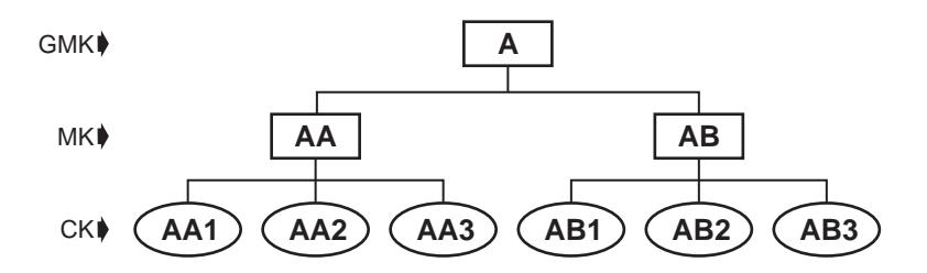
Standard Master Key System: 2 Levels of Keying
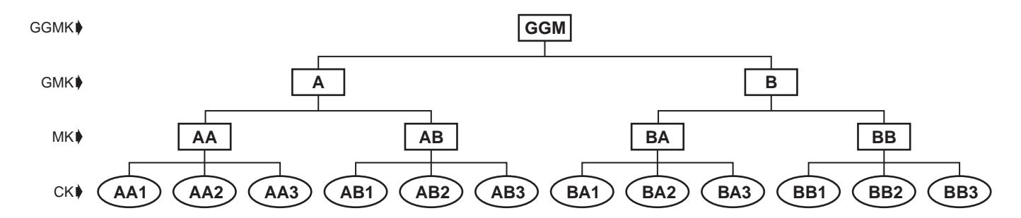
Grand Master Key System: 3 Levels of Keying
Master key is assigned two letters. Change key numbers come before the MK letters.
Grand master key is assigned one letter. Masters under the GMK are assigned two letters, the first being the same as the GMK letter. Change keys numbers come after the MK letters.
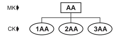
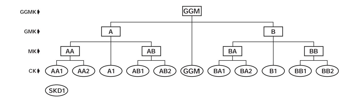
Great Grand Master Key System: 4 Levels of Keying
Great grand master key has the symbol of GGM. Grand master keys are each assigned one letter. Masters under the GMK are assigned two letters, the first letter being the same as the GMK letter. Change key numbers come after the MK letters.
Special Keying Situations
Cylinder is operated by the change key and GMK, but no MK: Change key numbers come after the single GMK letter. Example: A1, A2, B1, etc.
Cylinder is operated by change key and GGM only, but no GMK or MK: Use symbols GGM1, GGM2, etc.
Cylinder is operated by one of the system's change keys but no MK's of any level: Suffix "(NMK)" to the regular symbol. Example: 3AA(NMK), AA7(NMK), etc.
Cylinder is operated by no keys in the system other than its own individual key: Single keyed sets SKD1, SKD2, etc.

Master Keying
Master Key System Specifications
Refer to page 10 for the Key Bitting Specifications.
Expansion Specifications
KeyMark® systems should include expansion specifications which indicate the maximum planned quantity of theoretical bitting combinations needed at each level of keying. The expansion specification is the arithmetic expression of the expansion in the form of numbers separated by dashes. Each number refers to the level of keying system to which it relates.
Examples:
For a 2-level system requiring fifty change keys, the expansion specification would be: 1-50
For a 3-level system requiring two masters under the grand and forty change keys under each master, the expansion specification would be: 1-2-40
For a 4-level system requiring three grands each with ten masters with fifty changes, the expansion specification would be: 1-3-10-50
The number of changes needed directly operated by the GGM or GM is indicated in parenthesis after that level's specification. For example: 1(10)-4-75 would be read "one grand master with four masters under the grand, seventy-five changes under each master, and ten changes directly under the grand master only."
The following charts are examples of master keying specifications for KeyMark 6- and 7-pin master key systems:
| 6-pin | ||||||||||||
|---|---|---|---|---|---|---|---|---|---|---|---|---|
| GGM | GM | MK | CK | |||||||||
| Level 2 | 1 | 4096 | ||||||||||
| A | 1 | 4 | 1024 | |||||||||
| Level 3 | B | 1 | 16 | 256 | ||||||||
| C | 1 | 64 | 64 | |||||||||
| A | 1 | 4 | 4 | 256 | ||||||||
| Level 4 | B | 1 | 4 | 16 | 64 | |||||||
| C | 1 | 16 | 16 | 16 | ||||||||
| 7-pin | ||||||||||||
|---|---|---|---|---|---|---|---|---|---|---|---|---|
| GGM | GM | MK | CK | |||||||||
| Level 2 | 1 | 16384 | ||||||||||
| A | 1 | 4 | 4096 | |||||||||
| Level 3 | B | 1 | 16 | 1024 | ||||||||
| C | 1 | 64 | 256 | |||||||||
| A | 1 | 4 | 4 | 1024 | ||||||||
| Level 4 | B | 1 | 4 | 16 | 256 | |||||||
| C | 1 | 16 | 16 | 64 | ||||||||
Notes
The ASSA ABLOY Group is the global leader in access solutions. Every day we help people feel safe, secure, and experience a more open world

MicroShield®
ASSA ABLOY Group companies offer MicroShield<sup>®</sup>, an anti-microbial coating for door hardware. MicroShield uses proven silver ion-based technology from Agion<sup>®</sup>, a leading provider of antimicrobial solutions, to stem the spread of bacteria and other microbes.
is a registered trademark of ASSA ABLOY Access and Egress Hardware Group, Inc.

The Agion® antimicrobial is not intended as a substitute for good hygiene. Coated products must still be cleaned to ensure the surfaces will be free of destructive microbes. ASSA ABLOY makes no representations or warranties, express or implied, as to the efficacy of the Agion® antimicrobial. A copy of the Agion® warranty is available upon request. Agion® is a registered trademark of Agion Technologies, Inc., Wakefield, MA, USA.