ASSA ABLOY ACCENTRA KRM200FWS Key Removable Windstorm Mullions Installation Instructions_80-7401-0204-000
Open the original PDF document
View PDFKRM200FWS Mullions
Installation Instructions
Tools Required:
Measuring Tape Pencil #7 Drill and 1/4"-20 Tap Concrete Drill 3/8" diameter 1/2" Drill Punch Hammer #3 Phillips Screw Driver 5/64" Allen Wrench
3/16" Allen Wrench
Attention: Before starting the installation make sure that
- -You have the correct product
- -Doors are properly installed and hinge screws are secure
-
1. Attach the top retainer to the top jamb.
- a. Mark the centerline of the top retainer on the top jamb.
- b. Close the doors and keep door leaves tight to the stops.
-
c. Fold the supplied template 80-7401-0206-000 along the creased line and locate it on the top jamb using the centerline marked. Attach it to the frame and doors with self adhesive strips supplied.
- d. Mark drill and tap holes required.
- e. Install the top retainer using (4) four 1/4-20 x 5/8" flat head screws.
- 2. Locate the bottom retainer on the floor. Attention: Do NOT attach the retainer to the floor at this point.
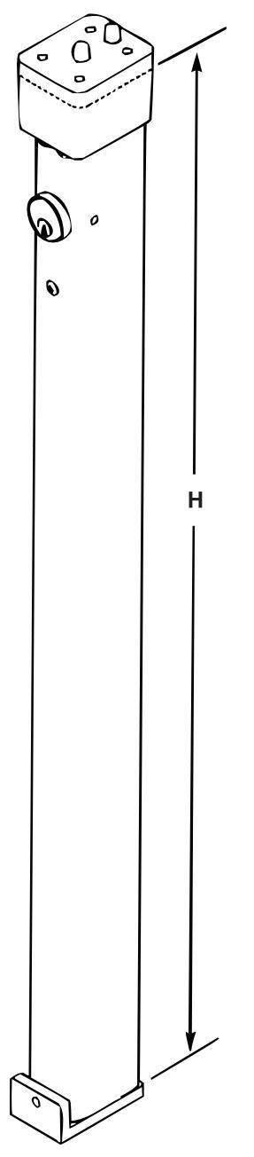
- 3. Cut the mullion body to size.
- a. Measure the distance (H) between the inside surface of the top retainer and the top of the bottom retainer surface as shown.
- b. Cut off bottom of the mullion body to desired length (L) using the following formula L = H - 1/16" (1.6)
- 4. Position the mullion body into the bottom and top retainers and locate it vertically. Mark the bottom retainer location on the floor (Bottom retainer still free to move). Attention: Make sure that the mullion surface is engaged with the doors and mullion is plumb to door face and frame.
-
5. Install the bottom retainer.
- a. Remove the mullion body from the retainers and put it aside.
- b. Align bottom retainer with previous markings from Step 4.
- c. Use a punch and hammer to mark hole locations on floor.
- d. Drill (2) 3/8" (9.5) dia. holes in floor to a min. depth of 2-5/8" (66.7).
- e. Mount the bottom retainer to the floor with supplied (2) 3/8" fasteners.
WARNING
This product can expose you to lead which is known to the state of California to cause cancer and birth defects or other reproductive harm. For more information go to www.P65warnings.ca.gov.
WARNING
80-7401-0204-000 04/24 Attention Installer: Any retrofit or other field modification to a fire rated opening can potentially impact the fire rating of the opening, and ASSA ABLOY makes no representations or warranties concerning what such impact may be in any specific situation. When retrofitting any portion of an existing fire-rated opening, or specifying and installing a new fire-rated opening, please consult with a code specialist or local code official (Authority Having Jurisdiction) to ensure compliance with all applicable codes and ratings.
1-855-557-5078 Ext. 2 • www.accentra-assaabloy.com
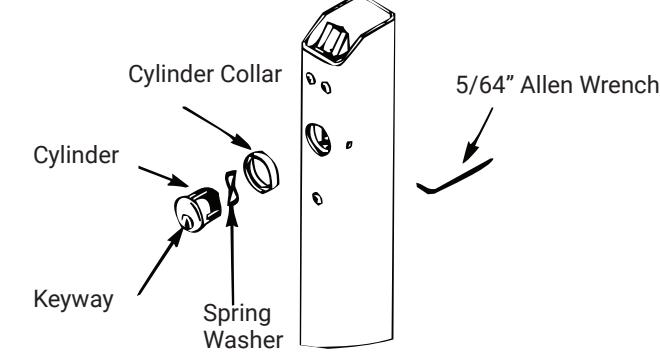
6. Installation of Cylinder
- a. Depress latchbolt and hold fully retracted.
- b. Carefully thread cylinder with cylinder ring into lock assembly until it bottoms out.
- c. Unscrew the cylinder orienting keyway at bottom.
- d. Release latch bolt. Note: If latch bolt is not fully projected, loosen cylinder an additional 1-2 full turns.
- e. Tighten set screw with 5/64" Allen Wrench through access hole in side of mullion.
- f. Check operation of cylinder and lock assembly.
NOTE: Key only turns counter clockwise.
7. Install the mullion body.
- a. Place mullion body onto bottom retainer and pivot into opening.
- b. Tighten bottom retainer set screw with 3/16" Allen Wrench to prevent mullion rattle.
- 8. Install exit devices according to the manufacturer's instructions.
9. Fire rated Rim and SquareBolt® Exit Devices
After exit devices and strikes have been assembled, install Interlock
Brackets with #10-24 x 3/4" screws as shown in illustration below.
Interlock Bracket Required for Fire Rated SquareBolt® and Rim Exit Device with Mullion.
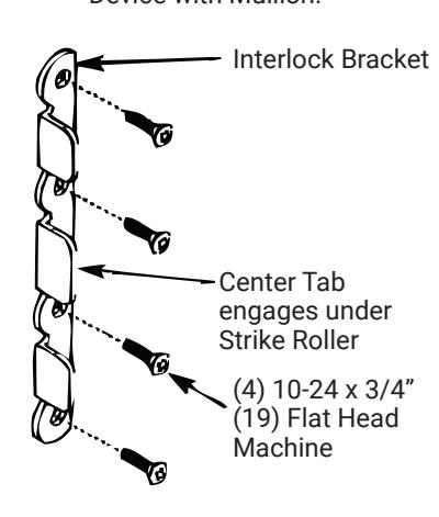
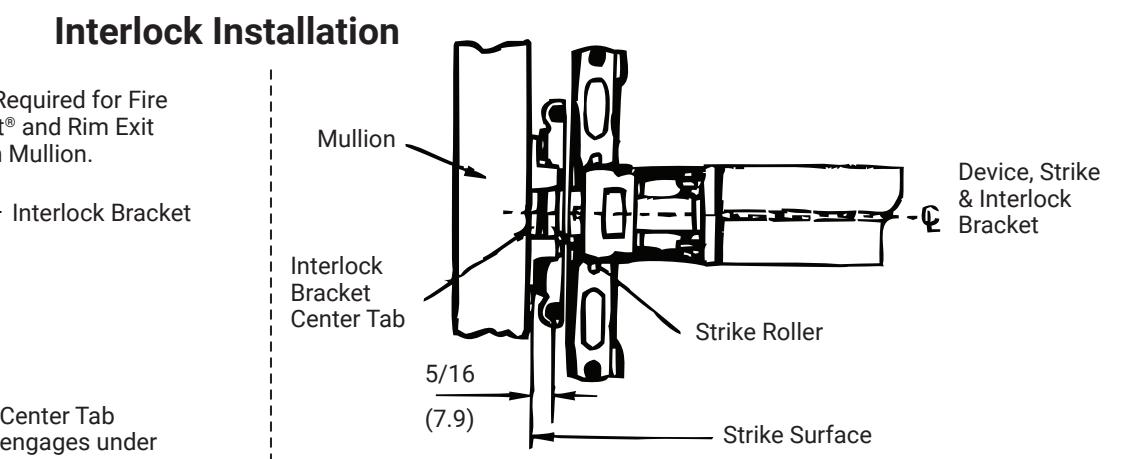
- 1. Position strike Interlock Bracket in place, as shown. Locate bracket holes.
- 2. Prepare Interlock Bracket mounting holes and mount with (4) 10-24 x 3/4" screws (and SNG's when applicable).
80-7401-0204-000 04/24