ASSA ABLOY ACCENTRA KRM200(F) Key Removable Mullions Installation Instructions_80-7401-0201-000
Open the original PDF document
View PDF

KRM200 & KRM200F Mullions Installation Instructions

Any retrofit or other field modification to a fire rated opening can potentially impact the fire rating of the opening, and Yale Locks & Hardware makes no representations or warranties concerning what such impact may be in any specific situation. When retrofitting any portion of an existing fire rated opening, or specifying and installing a new fire-rated opening, please consult with a code specialist or local code official (Authority Having Jurisdiction) to ensure compliance with all applicable codes and ratings.
Tools Required:
Measuring Tape Pencil Drill & Tap Sizes #7 drill and 1/4"-20 tap Concrete Drill 3/8" diameter Center Punch Hammer #3 Phillips Screw Driver 5/64" Allen Wrench 1/8" Allen Wrench
- 1. Close and block doors against frame stops. Check gap between door leaves and door to frame and correct if necessary.
-
2. Locate the center of the opening on the floor. Using the bottom retainer, mark the positions for the two drop-in fasteners.
- a. The bottom of the door should come to rest against the surface of the mullion.
- b. Modify threshold as required.
- 3. Drill holes with 3/8" diameter cement bit to a minimum depth of 2-1/2" (63.5).
- 4. Fasten bottom bracket to floor.
-
5. Locate the center of the opening on the top of the frame. Using the top retainer, mark the positions for the four fasteners.
- a. The door should evenly rest against both the frame stop and the mullion.
- b. If a top retainer mounting kit is used, modify weatherstripping as required.
- 6. Drill and tap each location for 1/4"-20 fasteners.
- 7. Mount top retainer on frame with provided fasteners.
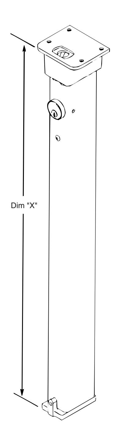
- 8. Measure "Dim X" as shown. Remove material from the bottom of the mullion per the formula length of mullion = "dim X" minus 3/4" (19). Note: This leaves approximately 1/8" (3.2) clearance between the mullion and the top bracket when mounted.
-
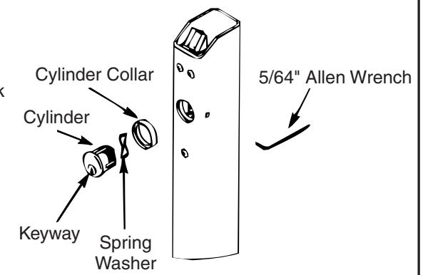
9. Installation of Cylinder
- a. Depress latchbolt and hold fully retracted.
- b. Carefully thread cylinder with cylinder ring into lock assembly until it bottoms out.
- c. Unscrew the cylinder orienting keyway at bottom.
- d. Release latch bolt. Note: If latch bolt is not fully projected, loosen cylinder an additional 1-2 full turns.
- e. Tighten set screw with 5/64" allen Wrench through acess hole in side of mullion.
- 10. Place mullion onto bottom bracket and pivot into opening to latch.
- 11. Tighten bottom bracket set screw to prevent mullion rattle.
- 12. Install exit devices according to the manufacturer's instructions.
- 13. Fire rated Rim and SquareBolt® Exit Devices
After exit devices and strikes have been assembled, install Interlock Brackets with #10-24 x 3/4" screws as shown in illustration below.
Interlock Installation
Interlock Bracket Required for Fire Rated SquareBolt® and Rim Exit Device with Mullion.
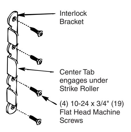
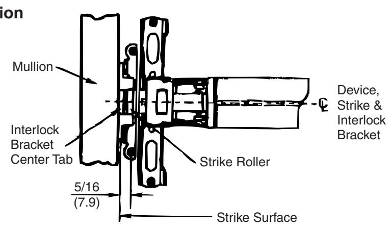
- 1. Position strike Interlock Bracket in place, as shown. Locate bracket holes.
- 2. Prepare Interlock Bracket mounting holes and mount with (4) 10-24 x 3/4" screws (and SNG's when applicable).
Product Support Tel 800.438.1951 • www.yalelocks.com
Yale Locks & Hardware is a division of Yale Security Inc., an ASSA ABLOY Group company.
Yale® and SquareBolt® are registered trademarks of Yale Security Inc., an ASSA ABLOY Group company. owners and are mentioned for reference purposes only. These materials are protected under U.S. copyright laws. All contents current at time of publication. Other products' brand names may be trademarks or registered trademarks of their respective
Yale Security Inc. reserves the right to change availability of any item in this catalog, its design, construction, and/or its materials. Copyright © 2008, 2013, Yale Security Inc., an ASSA ABLOY Group company. All rights reserved. Reproduction in whole or in part without the express written permission of Yale Security Inc. is prohibited.
80-7401-0201-000 (02-13)
2