ASSA ABLOY ACCENTRA Heavy Duty Parallel Arm (Non Hold Open) and Heavy Duty Parallel Arm_80-9358-0002-010
Open the original PDF document
View PDFINSTALLATION INSTRUCTIONS
Power sizes 1 thru 6
Inches (mm)
Heavy-Duty Non-Hold Open Parallel Arm w/Removable Stop
Heavy-Duty Hold Open Parallel Arm w/ Thumbturn and Removable Stop
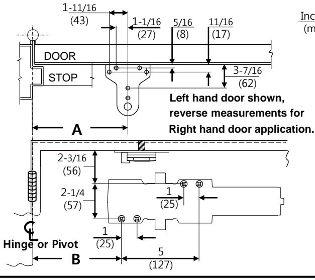
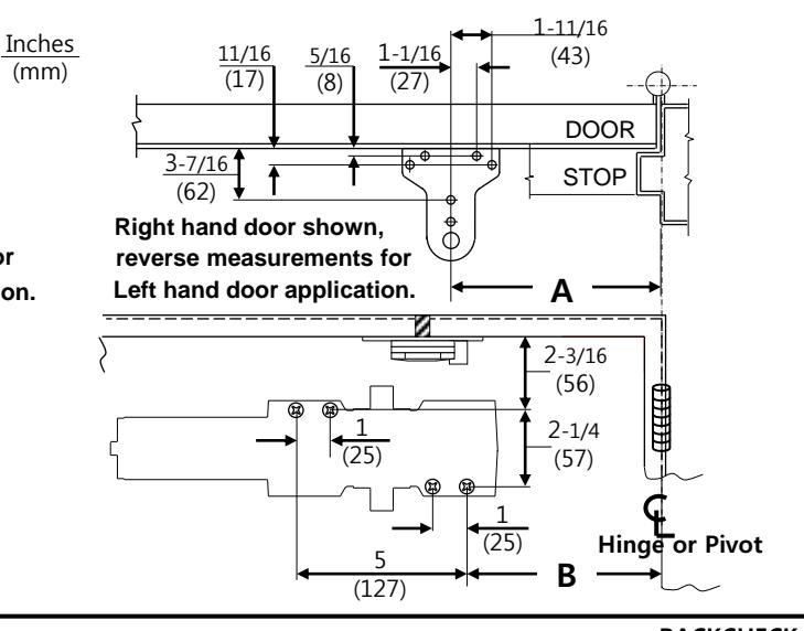
Using the measurements from diagram, mark screw hole center locations. Mark four (4) holes on door to mount door closer and five (5) holes on frame to mount parallel bracket. Drill 7/32" or drill #7 and tap for 1/4-20.
| Metal | Wood | ||
|---|---|---|---|
| #7 | evenue. | ||
| 1/4-20 | 3/16 " | ||
Incorrect installation or adjustment could cause damage or injury. Read and follow instructions carefully.
| OPENING | DIM. A | DIM. B |
|---|---|---|
| 85° | 10-1/2 (267) | 8-3/4 (222) |
| 90° | 10-1/32 (255) | 8-3/8 (212) |
| 100° | 9 (228) | 7-1/2 (190) |
| 110° | 8-1/32 (204) | 6-1/4 (158) |
2 DOOR CLOSER ADJUSTMENT
Power Adjustment Chart
(CLOCKWISE TURNS)
| POWER SIZE | 1 | 2 | 3 | 4 | 5 | 6 |
|---|---|---|---|---|---|---|
| 1 THRU 6 | -7 | -4 | PRESET | +5 | +10 | +15 |
REGULATION
Do not allow door to slam into frame.
A normal standard closing time from 90° open position is 5 to 7 seconds evenly divided between main closing (sweep) speed and latching speed. Adjust the CLOSING speed first, then adjust the LATCHING speed.
For slow closing speed of door, turn speed adjusting valve of "C" (closing speed) clockwise and counter-clockwise for fast.
Latching speed control of door is the same manner as closing speed adjustment.
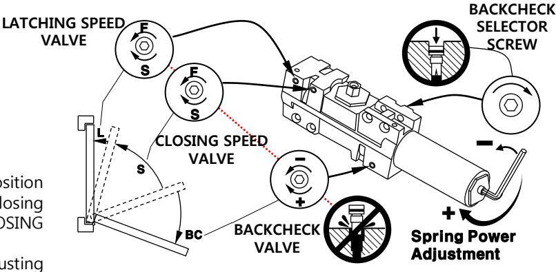
ADJUSTABLE BACKCHECK FUNCTION
This function is essential to the proper operation of the RIGID PARALLEL ARM. Use just enough to prevent arm from striking stop with impact.
3 BRACKET ADJUSTMENT
All brackets are shipped assembled for left hand door. The following adjustments must be made before installing bracket to top frame.
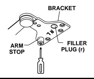
FOR LEFT HAND DOOR:
Using the phillips screwdriver, turn the REMOVABLE ARM STOP clockwise to seat as tightly as possible. Push filler plug in firmly.
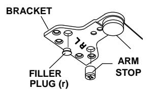
FOR RIGHT HAND DOOR: Remove filler plug from bracket. Using the phillips screwdriver turn the REMOVABLE ARM STOP counter-clockwise to remove it. Insert REMOVABLE ARM STOP into hole mark "R" and using the phillips screwdriver, turn clockwise to seat as tightly as possible. Push filler plug into the other hole firmly.
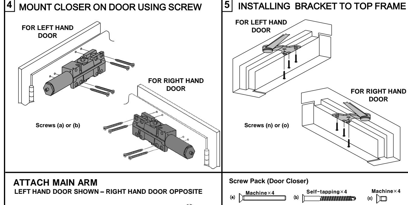
DOOR
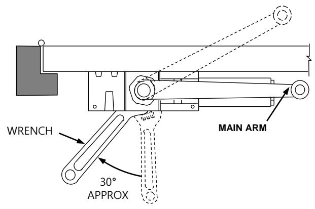
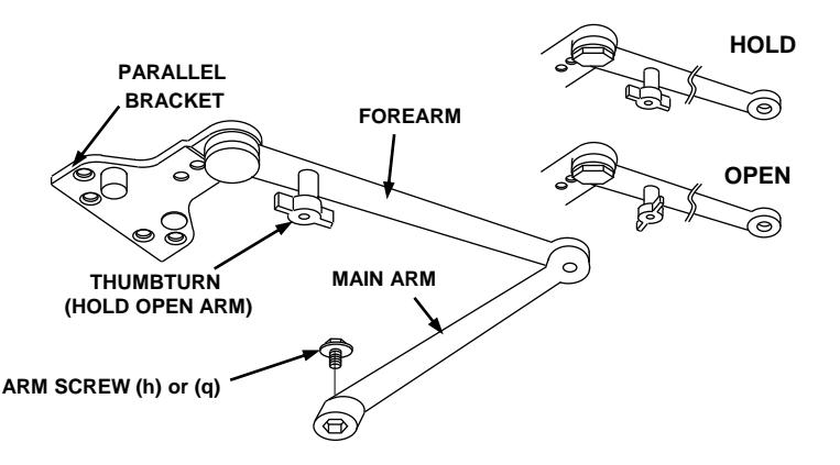
- 1. Remove stud at junction between MAIN ARM and Forearm.
- 2. IMPORTANT place open end wrench (spanner) on bottom shaft and turn toward hinge edge about 30°
- 3. Place MAIN ARM on top shaft parallel with door and secure with shaft screw with wrench
- 4. Attach BRACKET to door stop (Top jamb) as shown on page 1.
- 5. Swing door open about 30°, join main arm and forearm, insert stud and tighten securely.
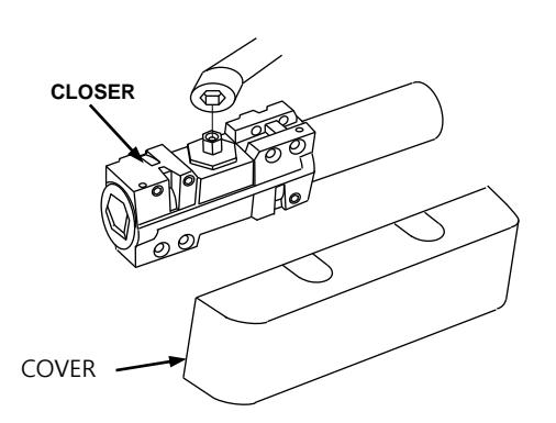
INSTALL FULL COVER
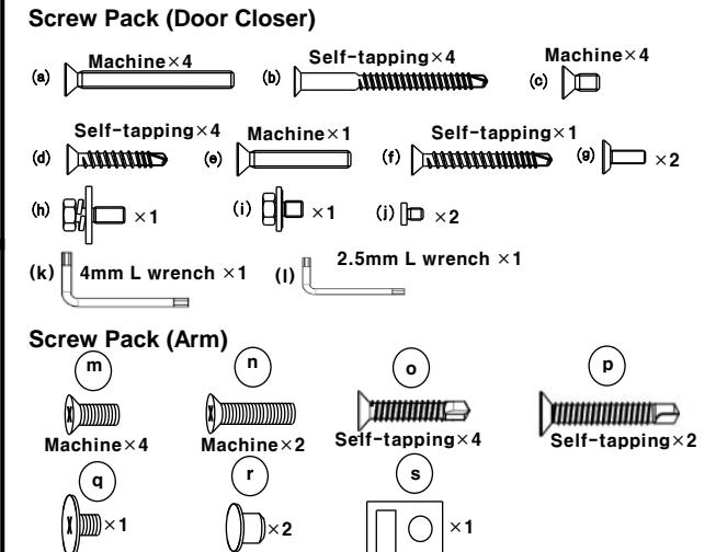
Slide cover insert into un-used cutout in cover. Install cover securely using screws provided.
HOW TO ENGAGE THUMBTURN
Turn one quarter turn to engage or disengage.
Rev. No. : 20140420-03 Page 2