ASSA ABLOY ACCENTRA Electric Dogging Installation Instructions_80-9460-6017-000
Open the original PDF document
View PDF6100 / 6200 Series
Exit Devices Electric Dogging
Installation Instructions
P Function and/or Monitors
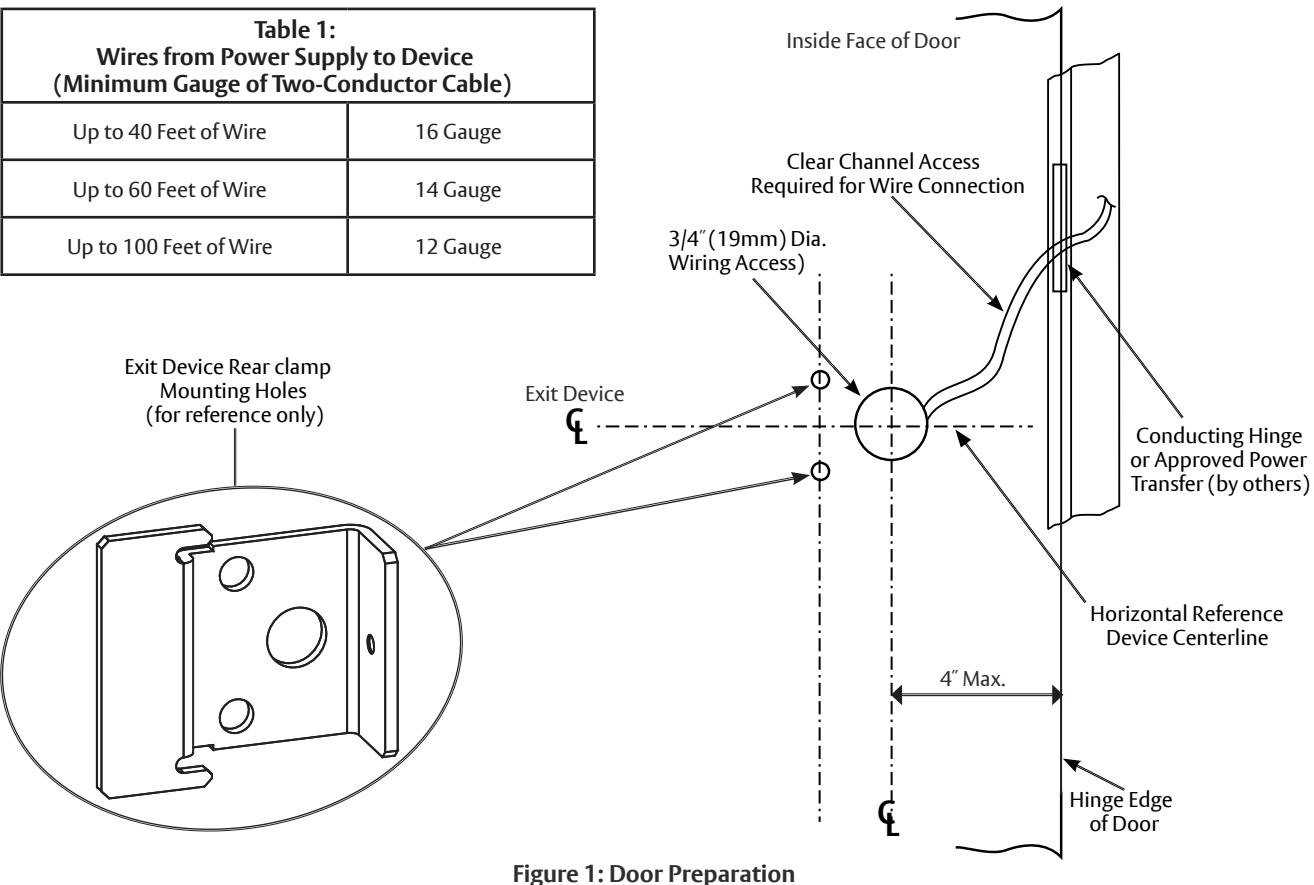
1. Install the System Peripheral Components (782 Controller, Controlling Switches, Power Transfer Hinge(s), etc.) and Raceways (Table 1)

IMPORTANT: Do not connect power until all components are installed.
Integral Power Supply: Connect the wires from the Power Transfer Hinge, Controlling Switch(es) Console and Power (120 VAC) input to the 782 Controller, as described in the controller installation instructions.
Power Transfer Hinge: Follow the manufacturers' installation instructions. The door leaf wires must exit through the door access hole, underneath the device rear clamp.
- 2. Install Device (and optional Trim): Follow the installation instructions for device (and trim). The Rear Clamp and End Cap are NOT to be installed at this time.
- 3. Prepare Wiring Access Hole: Drill a 3/4" (19mm) diameter hole in the door using the rear clamp center hole as a guide (Figure 1).
- 4. Install the rear clamp screws and fully tighten all device screws.
- 5. Check Device Action: Actuate the device by the touchbar (and trim). Be sure that the door and device are operating properly and that the door is opening freely and closing
6. Connect Device Electric Dogging Wires: The red (+) and black (-) polarized wires from the inactive (hinge) end of the device connect to DEV 1 on the 782 (see the wiring diagram).
ASSA ABIOY
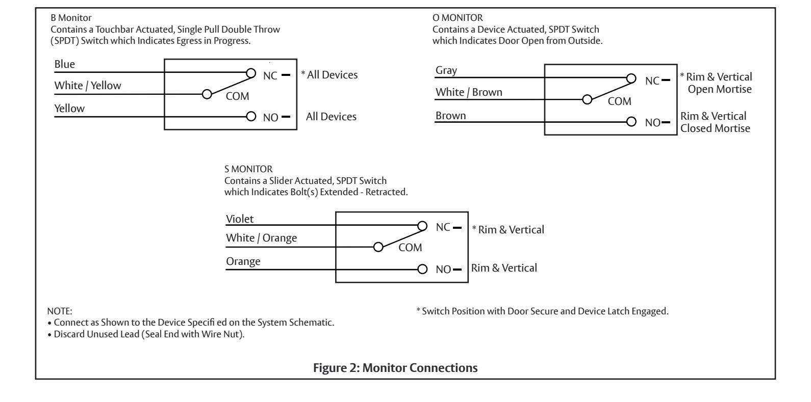
- 7. Connect Monitors (if used): Follow the connections shown in Figure 2. Wire nuts are not supplied.
- 8. Coordinated Door Operation: When two (2) devices are hooked to the same 782, repeat steps 2. through 7. and connect the second device to DEV 2.
- 9. Test System: With the power disconnected, verify there are no short circuits throughout.
Apply power to console (if used) and to integral power supply. Test the device; bolt should retract when the controlling switch closes contacts and extend when the switch contacts open.
During momentary or continued operation the device status will correspond to the switch
Note: The 782 Controller has an adjustable delay which causes the Electric Latch to remain retracted while the controlling switch is open. The Troubleshooting Guide (Table 2) provides
WARNING
This product can expose you to lead which is known to the state of California to cause cancer and birth defects or other reproductive harm. For more information go to www.P65warnings.ca.gov.

WARNING
Attention Installer: Any retrofit or other field modification to a fire rated opening can potentially impact the fire rating of the opening, and ASSA ABLOY makes no representations or warranties concerning what such impact may be in any specific situation. When retrofitting any portion of an existing fire-rated opening, or specifying and installing a new fire-rated opening, please consult with a code specialist or local code official (Authority Having Jurisdiction) to ensure compliance with all applicable codes and ratings.
80-9460-6017-000 01/24
|
Table 2:
Troubleshooting Guide |
|
|---|---|
| Problem |
Solutions
follow in sequence (defined below) |
| Device Does Not Work | 1, 2, 3, 6, 8 |
| Latchbolt(s) Are Not Retracting, But Relay Click Is Audible | 2, 4, 5, 6, 7, 8, 9 |
| Sluggish Bolt Retraction | 2, 4, 5, 6, 7, 9 |
| Bar Hot (Not Warm) | 2, 6, 8 |
| Bolt(s) Hangs Retracted | 1, 2, 5, 7, 8 |
| Bolt(s) Not Fully Retracting | 5, 7, 9 |
| Intermittent Action | 1, 4, 5, 6, 8, 9 |
| Solution Definitions | |
|
1.
Check Remote Switch(es) |
|
|
2.
Check Circuit Continuity |
|
|
3.
Check Fuses |
|
|
4.
Be Sure That The Door Swings Freely |
|
|
5.
Be Sure That The Manual Device Action Works Properly |
|
|
6.
Check Wiring (Connection and Insulation) |
|
|
7.
Check For Foreign Materials (Device Should Be Free From Obstructions) |
|
|
8.
Check Circuit Board Operation |
|
|
9.
Check Wires To Device (Gauge Vs. Length) |
|
80-9460-6017-000 01/24