ASSA ABLOY ACCENTRA D100 and D200 Series Deadbolts Single, Double, IC, Indicator Installation_263007820
Open the original PDF document
View PDFCylindrical Deadbolts Single/Double/IC/Indicator
Installation Instructions

WARNING
This product can expose you to lead which is known to the state of California to cause cancer and birth defects or other reproductive harm. For more information go to www.P65warnings.ca.gov.
⚠ WARNING
Attention Installer: Any retrofit or other field modification to a fire rated opening can potentially impact the fire rating of the opening, and ASSA ABLOY makes no representations or warranties concerning what such impact may be in any specific situation. When retrofitting any portion of an existing fire-rated opening, or specifying and installing a new fire-rated opening, please consult with a code specialist or local code official (Authority Having Jurisdiction) to ensure compliance with all applicable codes and ratings.
1-855-557-5078 Ext. 2 · www.accentra-assaabloy.com
Experience a safer and more open world

Single/Double/IC/Indicator Installation Instructions
1. Mark Holes
Using enclosed template, mark door as illustrated at desired lock height and correct basket.
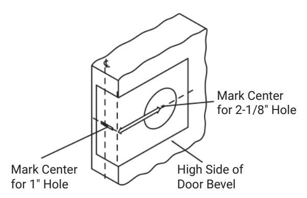
2. Bore two Holes
Drill 2-1/8" hole through both sides of the door as shown and 1" dia hole into front face of the door. Be certain holes are
perpendicular.
3. Install Deadbolt
a. Insert deadbolt in hole, keeping it parallel to face of the door and scribe line around face plate.
Bore 1" DIA. Hole Second
- b. Remove deadbolt and chisel out scribed area to depth of 5/32" or until face is flush with door edge.
- c. Insert deadbolt and fasten with two screws.
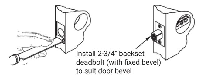
Bore 2-1/8" Hole First
d. Mortise frame for strike
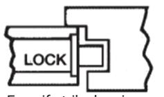
Even if strike box is not used, recess in jamb must be deep enough to allow bolt to extend its full length.
263007820 04/24
1-855-557-5078 Ext. 2 • www.accentra-assaabloy.com
Single/Double/IC/ Indicator
Installation Instructions
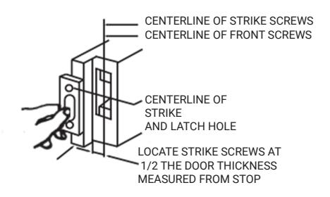
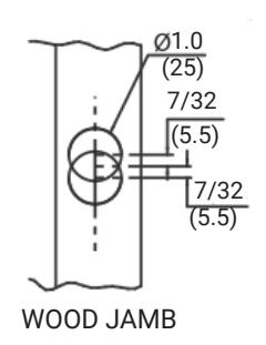
4. Install Strike on Wood Jamb
- a. Mark jamb exactly opposite centerline of latch hole. Bore two 1" dia. holes 7/32" above and below height line to depth of 1-1/8".
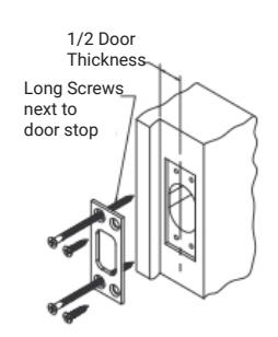
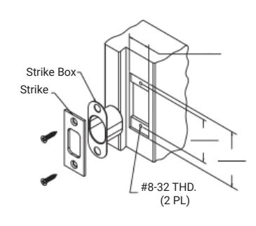
- b. Mortise for strike and box strike.
- c. Install and fasten four screws as illustrated.
Note: Drill 1/8" dia. pilot holes for 3/4" long screws, and 5/32" dia for 3" long screws.
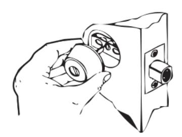
5. Install Strike on Wood Jamb
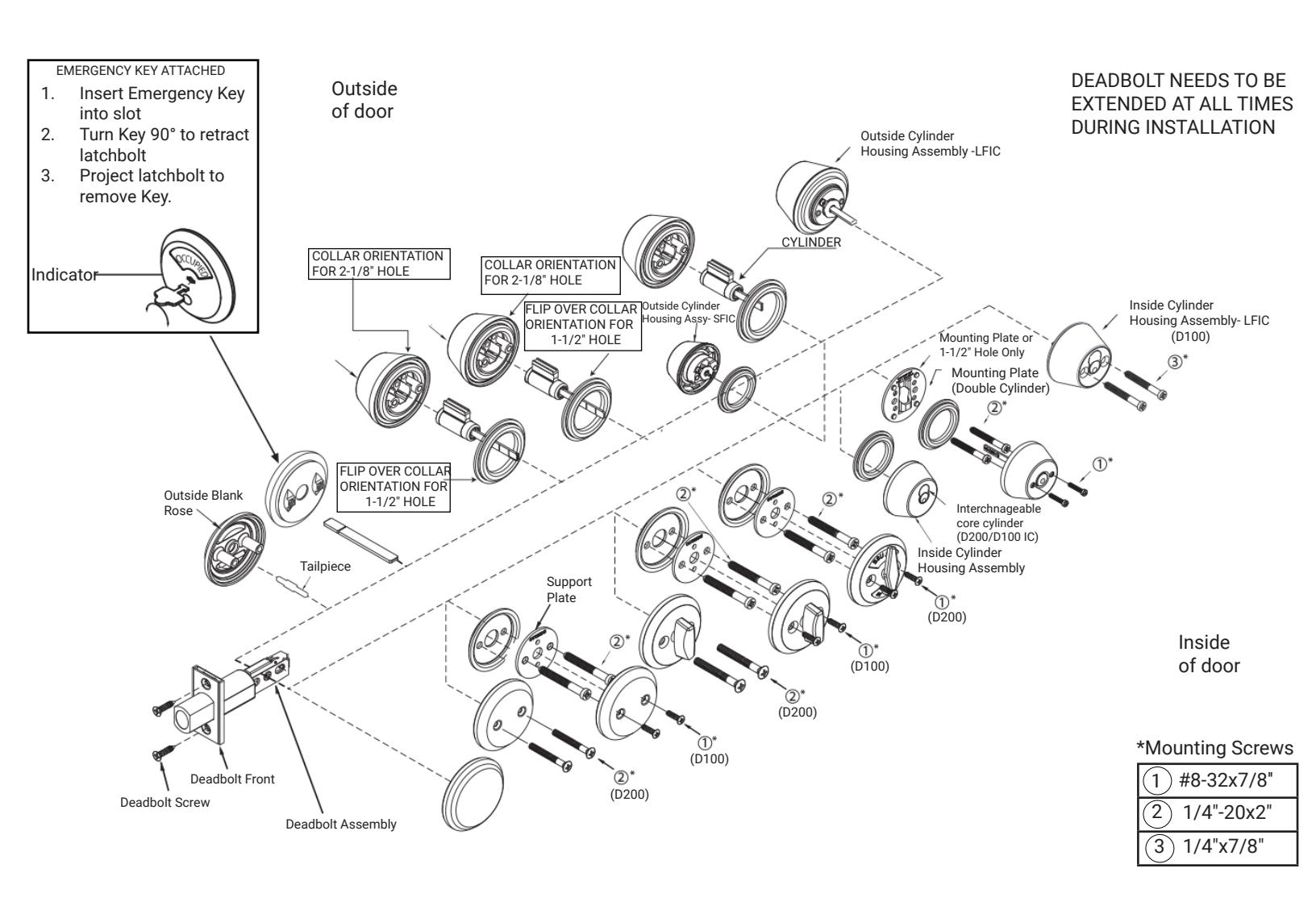
Extend deadbolt. Install cylinder housing without key keeping cylinder tailpiece in line with cam slot.
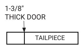
TAILPIECE MODIFICATION
- a. Mark jamb exactly opposite centerline of latch hole. Bore two 1" dia. holes 7/32" above and below height line to depth of 1-1/8".
- b. Mortise for strike and box strike.
- c. Install and fasten four screws as illustrated.
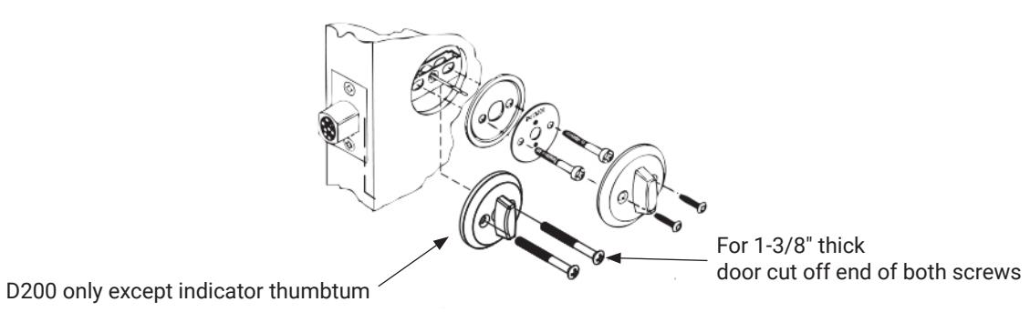
6. Attach Inside Trim
- a. Position mounting plate on door inside of the hole.
- b. Insert and tighten two 1/4"-20 machine screws.
- c. Place turn piece assembly onto tailpiece and align screw holes fasten with two turn piece screws.
Note:
- Check for proper operation before closing door.
- Do not use a power driver to tighten Housing Screws, only use hand tool for tightening and adjustments.
263007820 04/24

Single/Double/IC/Indicator Installation Instructions
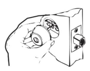
7. Double Cylinder-Inside
Install inside cylinder housing (with interchangeable core without key) keeping cylinder tailpiece in line with cam slot and mounting screws in line with holes of the deadbolt.
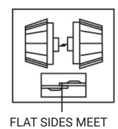
7A. Double Cylinder-Inside
Align outside cylinder housing (with interchangeable core without key) and position on door inside of the hole, making certain that tailpieces meet with flat sides and holes of outside cylinder housing align with mounting screws.
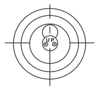
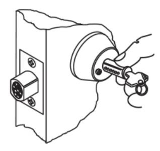
8. Small Format Interchangeable Core
Verify the cam is in the correct position before installing the core. If not, rotate cam to correct position, then install core.
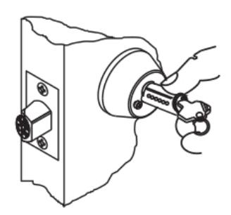
a. Remove cylinder by inserting control key, turn 15° to right and pull on key. Using cylinder, as shown, rotate face plate to the left to expose head of mounting screw.
263007820 04/24
Single/Double/IC/ Indicator
Installation Instructions
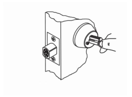
b. Tighten it using #2 Phillips screwdrive.
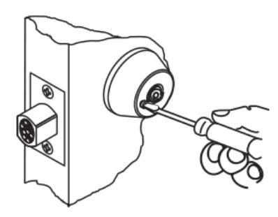
c. Using core, rotate face plate to the right and tighten second screw.
d. Rotate face plate to position to accept core. Insert interchangeable core into inside cylinder housing, turm control key to the left (this locks interchangeable core into assembly) and remote key.

Cylindrical Deadbolts Single/Double/IC/Indicator Installation Instructions
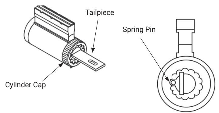
9. Change Tailpiece
Note:
All locks are preset for 1-3/4" Door Thicknesss
- a. Depress spring pin and unscrew cylinder cap.
- b. Remove and replace tailpiece . Screw cylinder cap on to plug while holding spring pin depressed until the cap is tight, then back off one or two notches as required.
- c. Check cylinder for proper clearance . If cap is too loose, the key cannot be withdrawn and if too tight, cylinder will bind. Make sure that spring pin is engaged with cylinder cap.
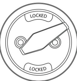
10.Thumbturn Indicator Re-handing
The thumbturn indicator is pre-configurated for Right Hand doors. See next steps to change handing for Left Hand doors.

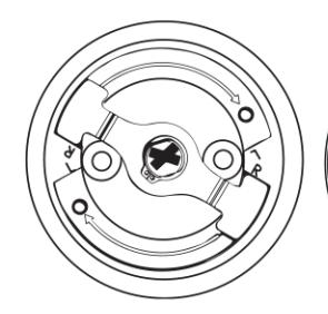
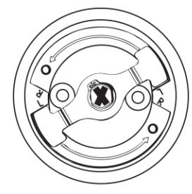
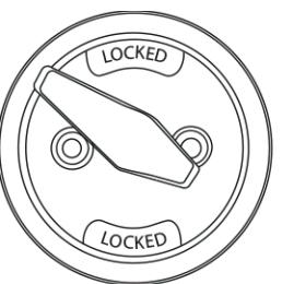
a. Position the inside thumbturn assembly as shown, while holding the ring in place. Push thumbturn in and rotate until the wheel clicks into the "L" (Left) on the opposite side.
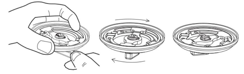
b. Rotate thumbturn to verify the mechanism operates correctly.
LEFT HAND SHOWN
263007820 04/24
1-855-557-5078 Ext. 2 • www.accentra-assaabloy.com
Cylindrical Deadbolts Single/Double/IC/ Indicator Installation Instructions

7