ASSA ABLOY ACCENTRA 8800 Series Mortise Locksets (Knob, Lever, Reflections and Security Trims) Installation Inst…_80-9086-0026-010
Open the original PDF document
View PDF8800 Series Mortise Lockset Knob, Lever, Refl ections®, and Security Trims

Installation Instructions
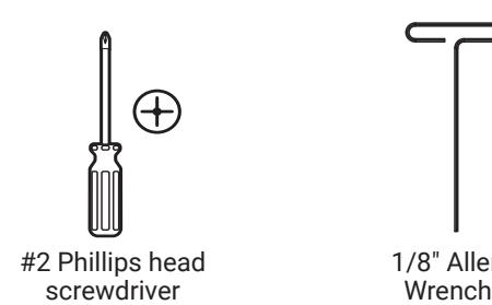
Tools Required

IMPORTANT!
The accuracy of the door preparation is critical for the proper functioning and security of this mortise lock. Misalignment can cause premature wear and tear and a lessening of security.
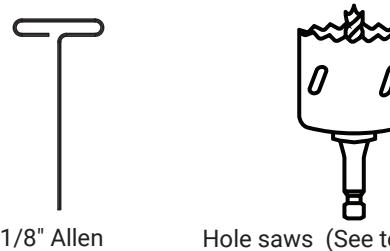
Hole saws (See template. Required sizes depend on application.)
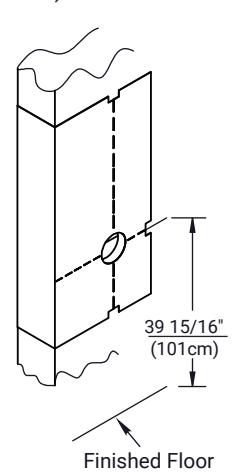
1. Mark and Drill Door
- A. Mark horizontal line across face of door 39-15/16" (101cm) is the usual lever height above the finished floor.
- B. Align the provided template center on the horizontal line. Before drilling, verify that the backset, door handing, and side of the door correspond to the side of the template being used.
2. Verify Handing
If required, adjust the handing for the lockbody.
Handing the Latchbolt
- A. Insert flat blade screwdriver into cover slot.
- B. Pull back on screwdriver until latchbolt extends past base front and rotate the head to the desired position.
Handing the Hubs
- A. Locate RED MARK on locking piece.
- B. Push toggle button slide away from "square spindle hole."
- C. With blade screw driver push RED MARK on slide nearest "square spindle hole."
- D. RED MARK indicates locked side.
WARNING
This product can expose you to lead which is known to the state of California to cause cancer and birth defects or other reproductive harm. For more information go to www.P65warnings.ca.gov.

Attention Installer: Any retrofi t or other fi eld modifi cation to a fi re rated opening can potentially impact the fi re rating of the opening, and ASSA ABLOY makes no representations or warranties concerning what such impact may be in any specifi c situation. When retrofi tting any portion of an existing fi re-rated opening, or specifying and installing a new fi re-rated opening, please consult with a code specialist or local code offi cial (Authority Having Jurisdiction) to ensure compliance with all applicable codes and ratings. 80-9086-0026-010 04/24
1-855-557-5078 Ext. 2 • www.accentra-assaabloy.com

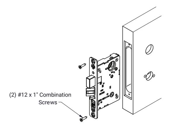
3. Install Lockbody
Insert lockbody in door. Ensure the bevel of the latchbolt faces the strike plate. Attach with two #12 x 1" combination screws. Leave attaching screws loose until the end when all will be tightened securely.
4. Install Trim
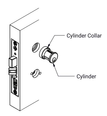
A. Install Cylinder (If applicable)
- 1. Insert cylinder through the cylinder collar, door and into lock.
- 2. Securely hand tighten cylinder set screw through the edge of the lock case.
NOTE: Do not use powered screw drivers to tighten cylinder set screw.
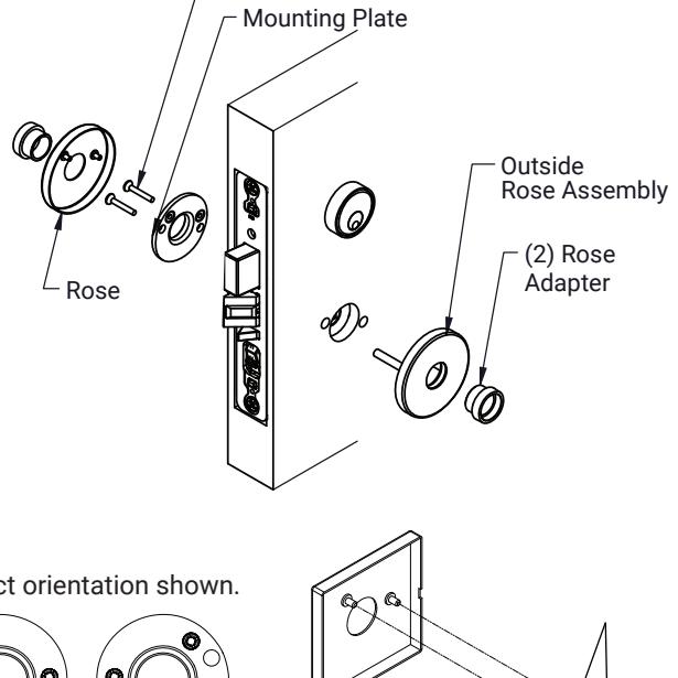
B. Rose Trim
- 1. Insert outside rose assemby (w/posts) through the door and into lock.
- 2. Align and fasten inside mounting plate with two #8-32 x 1" screws to posts.
- 3. Tighten screw securely.
- 4. Align and press rose posts to plastic bushings on mounting plate.
- 5. Go to Step 5, Page 5.
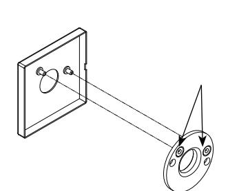
C. Square Rose Trim
1. Install cylinder with square collar and square rose trim, same as 4A and 4B.
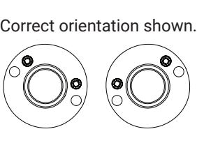
NOTE: The square rose and mounting plate needs to be oriented correctly during installation. Failure to do so causes roses that are crooked on the door, forcing the installer to remove and reinstall the parts. The proper orientation for the plastic rose-mounting inserts points in the upward direction. The rose is oriented with the slot facing the hinge side of the door.
Slot in trim must face towards the hinge side of door.
Go to Step 5, Page 5.
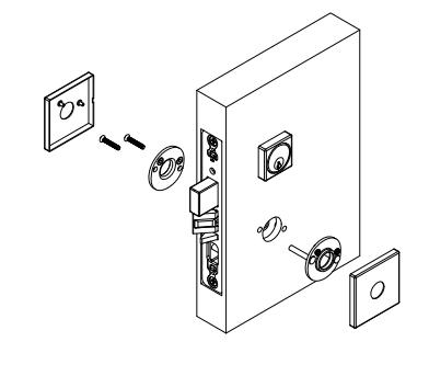
(2) #8-32 x 1" Attaching Screws
80-9086-0026-010 04/24
1-855-577-5078 Ext. 2 • www.accentra-assaabloy.com
4. Install Trim, continued
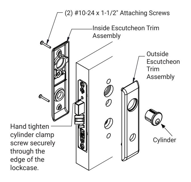
D. Escutcheon Trim - All types except SL
- 1. Insert outside escutcheon assembly (w/posts) through the door and into lock.
- 2. Align and fasten inside escutcheon with #10-24 x 1-1/2" screws to posts.
- 3. Align and fasten cylinder through escutcheon(s) and into lock body. Leave attaching screws loose until the end when all will be tightened securely.
- 4. Go to Step 5, Page 5.
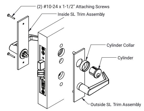
E. SL Escutcheon Trim
- 1. Insert outside escutcheon assembly (with posts) through the door and into lock.
- 2. Align and fasten inside escutcheon with #10-24 x 1-1/2" screws to posts.
- 3. Align and fasten cylinder and cylinder collar through escutcheon(s) and into lock body.
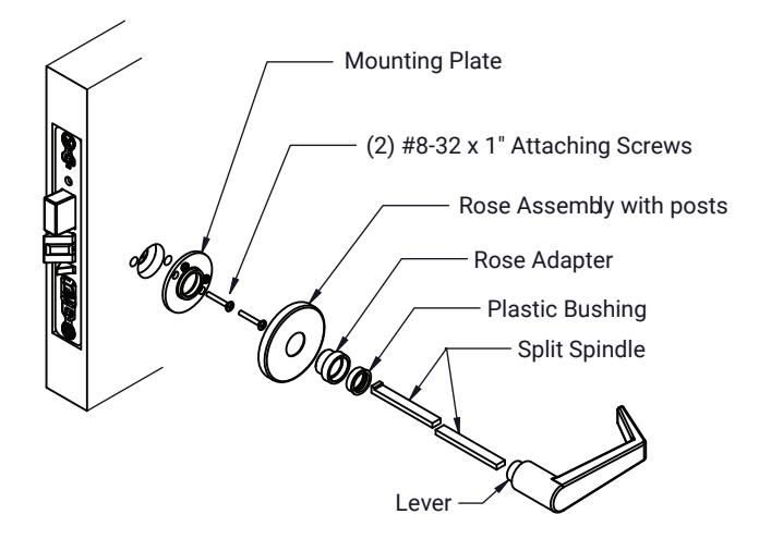
F. Single Sided Active Trim
- 1. Align and securely fasten mounting plate and #8-32 x 1" attaching screws to threaded posts in lockbody.
- 2. Align and press rose posts to plastic bushings on mounting plate.
- 3. Assemble rose adapter (not used on Reflections® ) in rose assembly.
- 4. Disassemble split spindles prior to installing into lock. Insert stepped spindle first, then insert non-stepped spindle. Insert lever on spindle assembly and tighten set screw located in the lever.
- 5. See Install Armor Front, Page 7, to complete installation.

4. Install Trim, continued
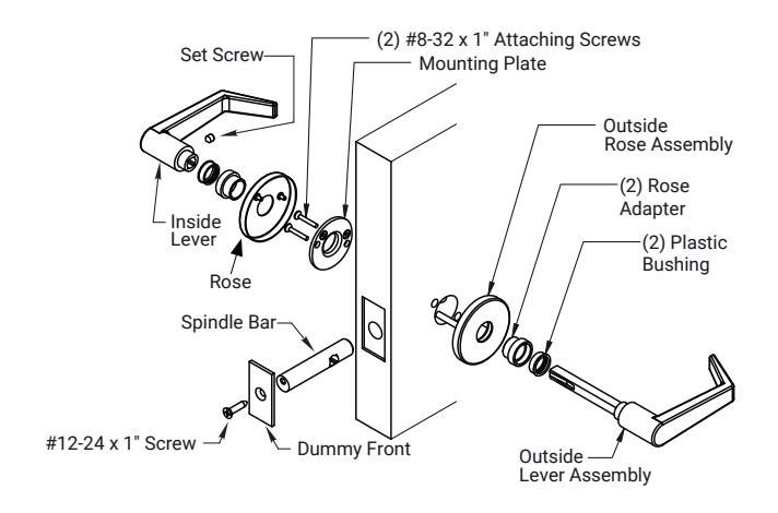
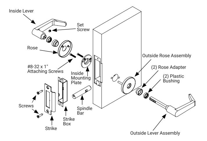
G. 838A Dummy Trim
- 1. Insert outside rose assembly (w/posts) through the door and align and fasten inside mounting plate with screws.
- 2. Align and press rose posts to plastic bushings on mounting plate. Slide spindle bar through edge of door, making sure the screw hole is in the top postion.
- 3. Insert outside lever assembly through rose assembly and into square hole in spindle bar.
- Assemble inside lever to outside lever assembly and tighten set screw located in inside lever.
- Attach dummy front to spindle bar with #12-24 x 1" attaching screw.
H. 838B Dummy Trim
- 1. Insert outside rose assembly (w/posts) through the door and align and fasten inside mounting plate with screws.
- 2. Align and press rose posts to plastic bushings on mounting plate. Slide spindle bar through edge of door, making sure the screw hole is in the top postion.
- 3. Insert outside lever assembly through rose assembly and into square hole in spindle bar.
- Assemble inside lever to outside lever assembly and tightenset screw located in inside lever.
- 5. Insert strike box and then attach strike to spindle bar with #12-24 x 1" screw. Use remaining #12 x 1" combination screw to attach the top of strike to the door.
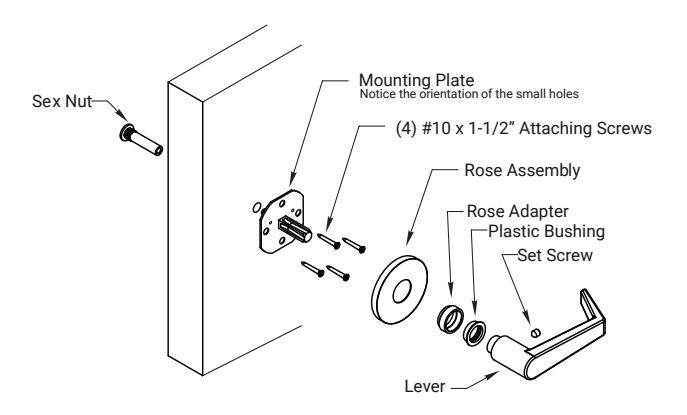
I. 855 Dummy Trim
- Align mounting plate over the intersection of previously marked horizontal line (lever height) and vertical backset centerline.
- 2. Mark the hole and drill with a 3/8" drill.
- Insert sex nut into door and thread mounting plate bolt into sex nut.
- Use lever hadle to tighten spindle. Check that the lever will be level when installed.
- 5. Drill pilot holes and fasten with four (4) attaching screws.
- 6. Slide Rose and Rose Adapter onto spindle.
- 7. Attach Lever and tighten set screw securely.

4. Install Trim, continued
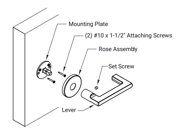
J. Refl ections® Lever 855 Dummy Trim
- 1. Align mounting plate over the intersection of previously marked horizontal line (lever height) and vertical backset centerline.
- 2. Mark holes through mounting plate. Drill pilot holes and fasten with two (2) attaching screws.
- 3. Slide Rose onto spindle.
- 4. Attach Lever and tighten set screw securely. Check that the lever will be level when installed.
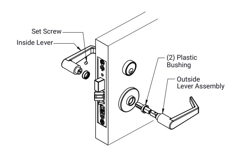
5. Install Lever or Knob Assembly
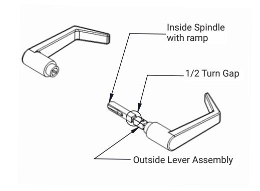
A. Prepare Lever or Knob Assembly - Not including SL Trim
- 1. Remove from packaging and remove inside lever/knob.
- 2. Unscrew the inside spindle from the outside lever assembly 1/2 turn and align the ramp in the horizontal position before inserting into the lock.
B. Install Lever Assembly or Knob Assembly on Rose and Escutcheon Trims
- Not including SL Trim
- Set Screw 1. Insert outside lever assembly through the rose or escutcheon trim and through the lockbody.
- 2. Insert inside lever onto the outside lever assembly spindle and tighten inside lever set screw.

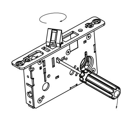
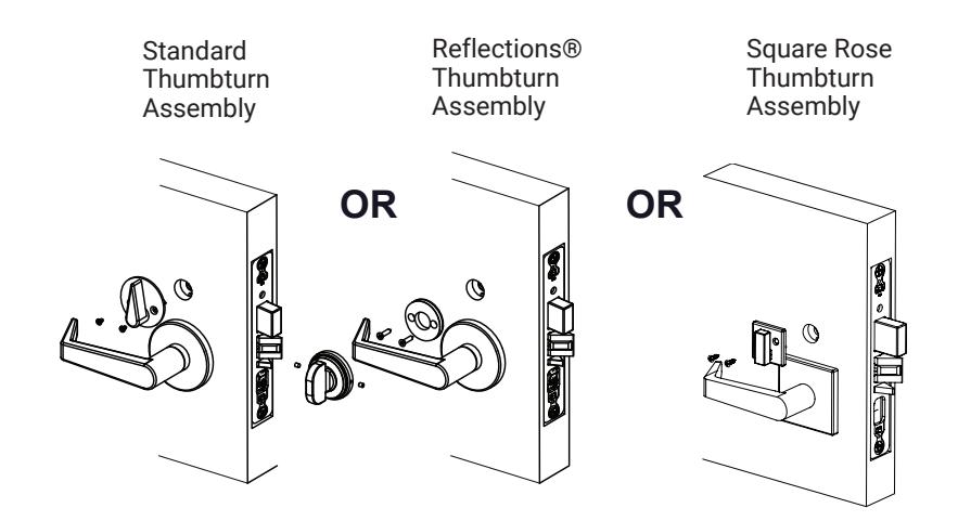
6. Install Thumbturn Assembly
NOTE: Thumbturn Assembly may be used on opposite sides of the door, dependant on the function.
- 1. Drill holes indicated for the thumbturn to be installed. (See template 7088-1009).
- 2. Install the lockbody in the mortise pocket (see Install Lockbody, Page 2).
- 3. Align the mechanism shaft through the Ø5/8" hole and into the square hub in the lockbody.
- 4. Install and tighten attaching screws.
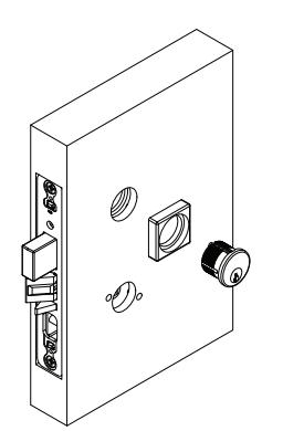
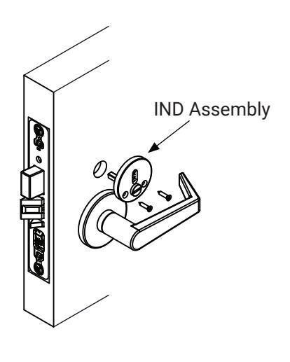
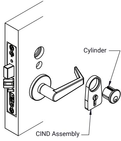
7. Install IND and CIND Assembly on the door
- 1. CIND Indicators may be used in conjunction with the thumbturn and most thumbturns are mounted on the egress side of the door.
- 2. Drill holes indicated for the function to be installed (see template 7088-1009).
- 3. Install the lockbody in the mortise pocket (see Install Lockbody, Page 2).
- 4. Align the CIND Assembly through the Ø5/8" hole and into the square hub in the lockbody.
- 5. Install the cylinder securely and fasten the cylinder clamp screw (see Install Cylinder, Page 2).
80-9086-0026-010 04/24
1-855-577-5078 Ext. 2 • www.accentra-assaabloy.com

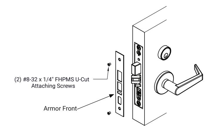
8. Install Armor Front
1. Align armor front to front of lockbody and attach screws.
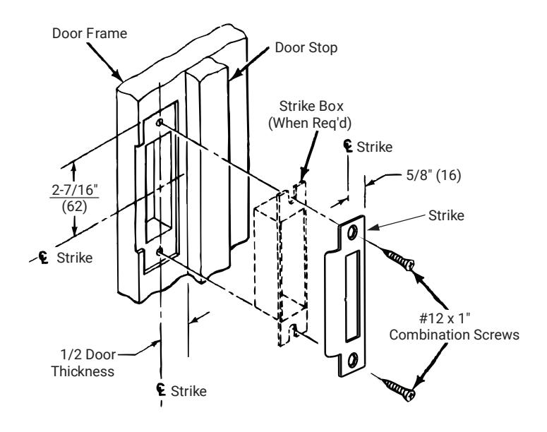
9. Install Strike
1. Attach strike to jamb using #12 x 1" combination screws.