ASSA ABLOY ACCENTRA 8800 Series-ITS Mortise Lockset Wiring Diagram and Installation Instructions_80-9086-0054-010
Open the original PDF document
View PDF8800-ITS Mortise Lockset
Wiring Diagram and Installation Instructions
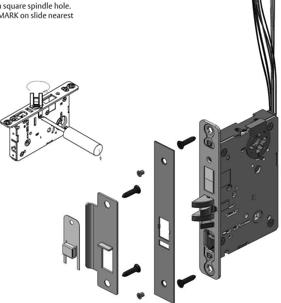
Handing the Latchbolt
- 1. Insert flat blade screwdriver into cover slot.
- 2. Pull back on screwdriver until latchbolt extends past base front and rotate the head to the desired position.
Handing the Hubs
- 1. Locate RED MARK on locking piece.
- 2. Push toggle button slide away from square spindle hole.
- 3. With blade screw driver push RED MARK on slide nearest square spindle hole.


WARNING
This product can expose you to lead which is known to the state of California to cause cancer and birth defects or other reproductive harm. For more information go to www.P65warnings.ca.gov.

WARNING
Attention Installer: Any retrofit or other field modification to a fire rated opening can potentially impact the fire rating of the opening, and ASSA ABLOY makes no representations or warranties concerning what such impact may be in any specific situation. When retrofitting any portion of an existing fire-rated opening, or specifying and installing a new fire-rated opening, please consult with a code specialist or local code official (Authority Having Jurisdiction) to ensure compliance with all applicable codes and ratings.
80-9086-0054-010 10/23
8800-ITS Mortise Lockset
Wiring Diagram and Installation Instructions
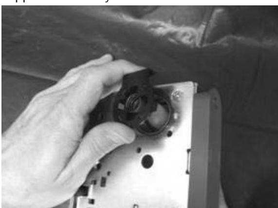
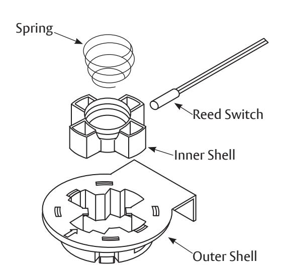
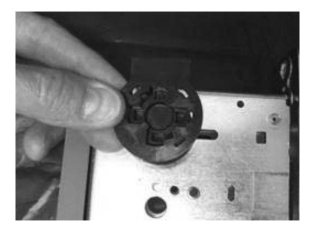
1. Remove Cylinder Monitor Assembly from Lockbody by gently pushing up through the opposite side of cylinder hole.
2. Remove spring from assembly. Use caution not to stretch or otherwise deform the spring.
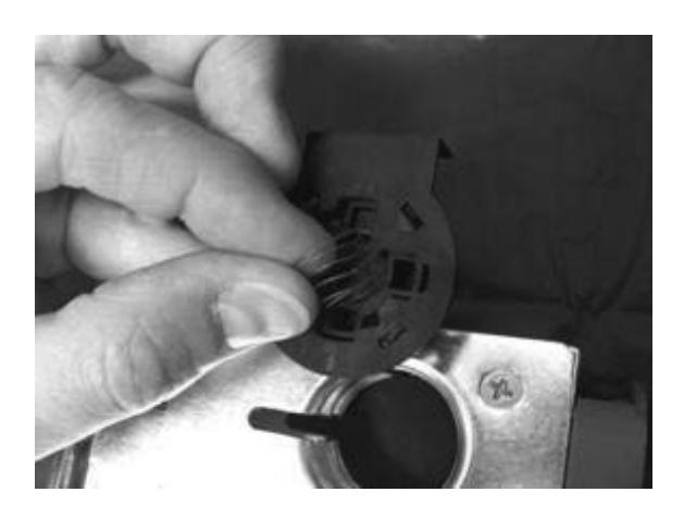
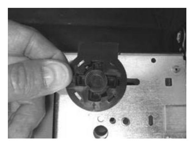
3. Remove Inner Shell from Outer Shell by gently pressing the Inner Shell upwards from the bottom. Use caution not to damage sensor wires.
80-9086-0054-010 10/23
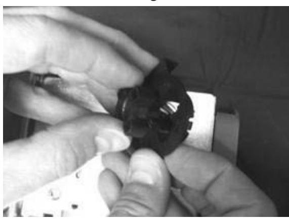
4. Turn Inner Shell on side. Align the inner shell with the diagonal slot in the Outer Shell. Slide the Inner Shell through the Outer Shell.

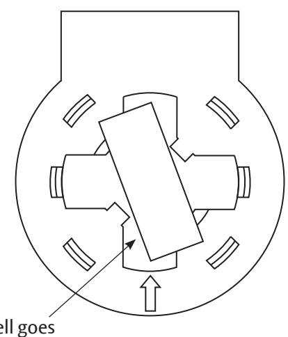
Inner Shell goes through here.
8800-ITS Mortise Lockset
Wiring Diagram and Installation Instructions
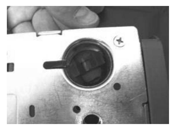
5. Feed Inner Shell (with wire and sensor) back through the Cylinder hole in the lockbody to the other side.
6. Turn the Inner Shell on its side and slide it down into the Outer Shell.
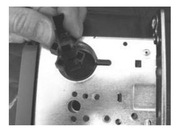
7. Assemble Inner Shell into Outer Shell. Guide the sensor wire out the top of the lock.
8. Install spring into assembly. Use caution not to stretch or otherwise deform the spring .
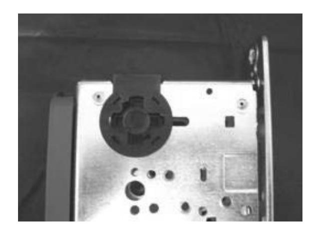
9. Gently press Cylinder Monitoring Assembly into cylinder hole on the new side of the lockbody.
ASSA ABLOY
ELECTRIFIED OPTIONS
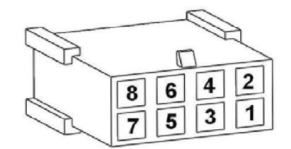
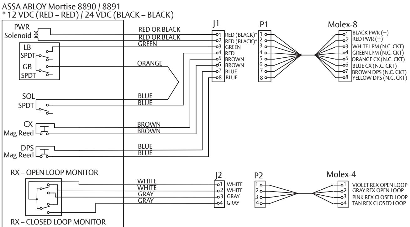
| Molex® | 8890 Options | 8891-ITS | |||
|---|---|---|---|---|---|
| Function | Color | Function | Color | ||
| 8-pin | 1,2 | Power | Black/Red | Power | Black/Red |
| LPM | Green/Gray | ||||
| 3,4 | OR | LPM | Green/Gray | ||
| LBM | Green/Green | ||||
| 5,6 | DB-In | Yellow/Yellow | CX | Brown/Brown | |
| 7,8 |
DPS*
(Less DB) |
Blue/Blue | DPS* | Brown/Blue | |
| 4-pin | 1,2 | Open Loop REX | White/White | Open Loop REX | White/White |
| 3,4 | Closed Loop REX | Gray/Gray | Closed Loop REX | Gray/Gray | |
* Deadbolt not available with DPS function.
| REFERENCES | |||
|---|---|---|---|
| REX | Request to Exit | ||
| LBM | Latch Bolt Monitor | ||
| LPM | Latch Performance Monitor | ||
| DBM | Deadbolt Monitor | ||
| DB | Deadbolt | ||
| DB-In | Deadbolt Retracted | ||
| DB-Out | Deadbolt Extended | ||
| DPS | Door Position Sensor | ||
| CX | Cylinder Monitor | ||
1-800-438-1951 • www.assaabloy.com
Experience a safer and more open world
80-9086-0054-010 10/23