ASSA ABLOY ACCENTRA 8800 Series Electrified Mortise EcoFlex Locks Installation Instructions_80-8800-0002-000
Open the original PDF document
View PDF8800 Series Electrified Mortise EcoFlex® Locks

Installation Instructions
1. Installation Notes
- Doors manufactured by ASSA ABLOY Group Companies are available pre-wired with ElectroLynx® connectors.
- Doors without ElectroLynx connectors will have to be hard wired.
-
For Non ElectroLynx Connector System Door:
- » Install available Retrofit Harness and use with ElectroLynx Hinge.
- » Follow installation instructions for ElectroLynx Connector System.
-
For Non ElectroLynx Connector System Door and Hinge:
- » Remove connector on lock.
- » Use proper crimp splices or wire nuts in accordance with local code for terminating connections.
- » Lock is polarity sensitive.
- The system shall not be installed in fail secure mode unless permitted by the local authority having jurisdiction and shall not interfere with the operation of Listed panic hardware.
- Wiring methods shall be in accordance with the National Electrical Code (ANSI/NFPA70), CSA 22.1, Canadian Electrical Code (CEC), Part I, Safety Standard for Electrical Installations, local codes and the authorities having jurisdiction.
2. Electrical Specifications (Fail Safe/Fail Secure)
- Current draw: 15mA @ 12V or 24V Continuous
- Peak current draw: 500mA @ 12V or 24V (Max 2 locks per 1A Power Supply)
- Monitor switch rating: 2A Max to 30VDC
Note: Operating voltage not to exceed +/- 10%
Wire Gauge Chart
|
Total One-Way
Length of Wire Run (ft) |
12VDC
Load Current @ 12VDC |
24 VDC
Load Current @ 24VDC |
||
|---|---|---|---|---|
| 1/2A | 1A | 1/2A | 1A | |
| 100 | 18 | 14 | 20 | 18 |
| 150 | 16 | 12 | 18 | 16 |
| 200 | 14 | 12 | 18 | 14 |
| 250 | 14 | 10 | 16 | 14 |
Note: The minimum permissible wire size to be used shall not be less than 26 AWG. When calculating voltage drop, use 0.5A as the recommended current draw.
WARNING
This product can expose you to lead which is known to the state of California to cause cancer and birth defects or other reproductive harm. For more information go to www.P65warnings.ca.gov.
WARNING
Attention Installer: Any retrofit or other field modification to a fire rated opening can potentially impact the fire rating of the opening, and ASSA ABLOY ACCENTRA™ makes no representations or warranties concerning what such impact may be in any specific situation. When retrofitting any portion of an existing fire-rated opening, or specifying and installing a new fire-rated opening, please consult with a code specialist or local code official (Authority Having Jurisdiction) to ensure compliance with all applicable codes and ratings.
80-8800-0002-000 01/24

8800 Series Electrified Mortise EcoFlex® Locks
Installation Instructions
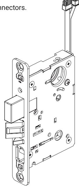
3. Door Preparation
Refer to Templates 7086-8003 or 7086-8004 for door preparation. Use door marker provided with lock to verify dimensions.
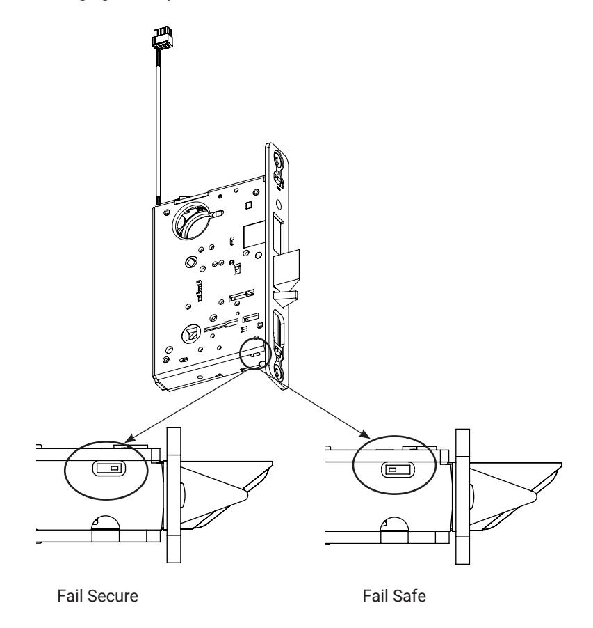
4. Verify/Configure Lock for Fail Safe or Fail Secure
Locks are configurable for Fail Safe or Fail Secure applications, locate dip switch on the bottom of the lockbody case as shown below.
- Dip switch can only be accessed prior to lock installation.
- Power cycling is required after changing switch position.
8800 Series Electrified Mortise EcoFlex® Locks
Installation Instructions

5. Installation
Install lock per instruction sheet 80-9086-0026-010 provided with lock.
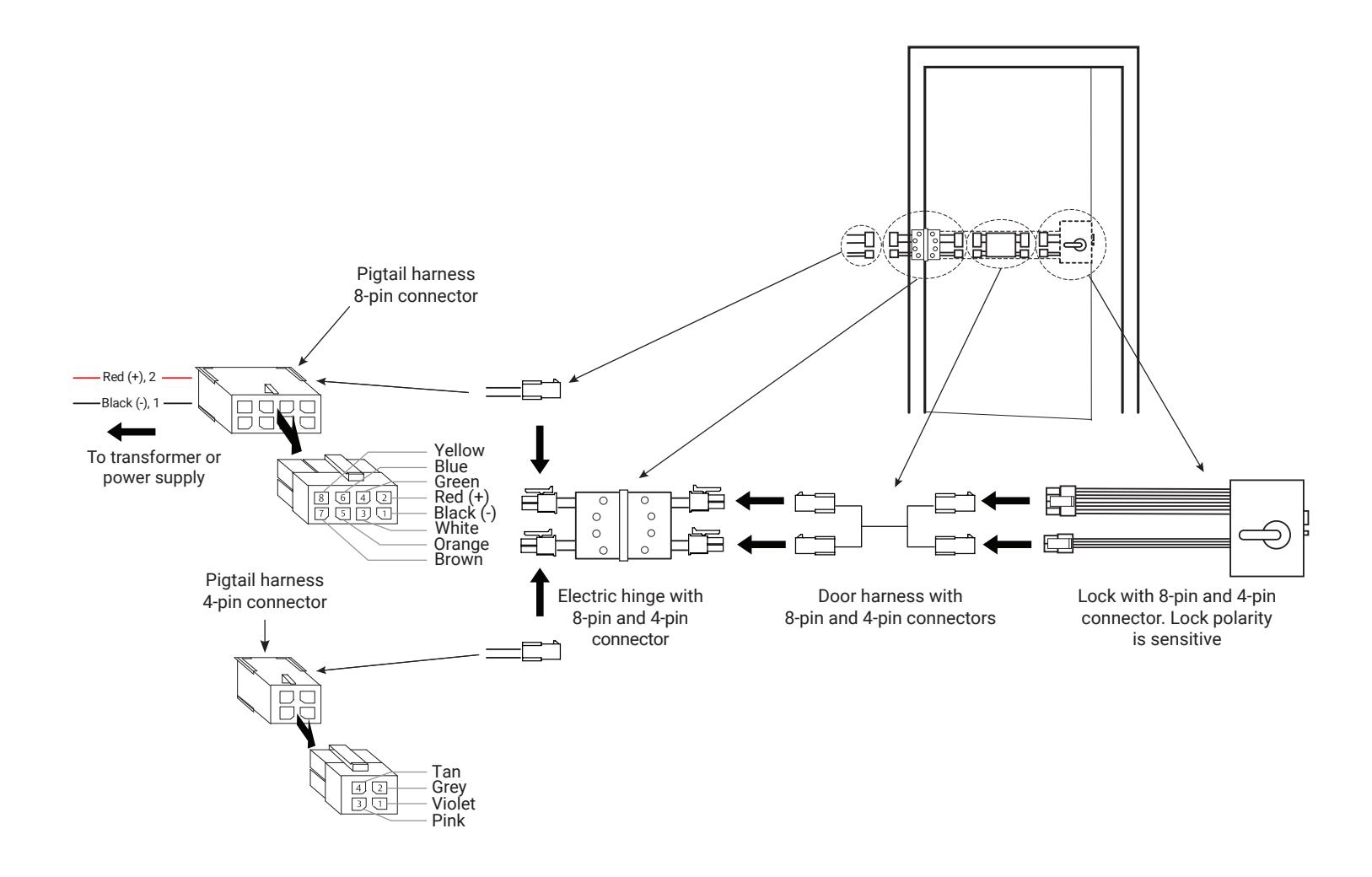
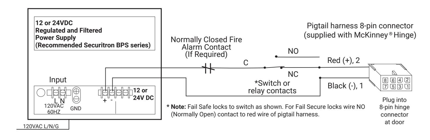
- 1. Plug electric hinge and lock connectors into raceway connectors or wire to pigtail harness using wiring diagram
- 2. Ensure proper supply voltage is being applied at pigtail harness.
Caution: The DC voltage must not vary beyond 12V+/- 10% or 24V+/- 10%. If voltage exceeds these values, the lock may be damaged or not function.
- 3. Plug pigtail harness 8-pin and 4-pin (if present) connector into electric hinge 8-pin and 4-pin connectors.
- 4. Test lock Applying 12 or 24VDC unlocks fail secure applications and locks fail safe applications.
80-8800-0002-000 01/24

6. Wiring Diagram
Wiring shows power on and lock in secure state
7. Electrified Options
| Č. | |||||
|---|---|---|---|---|---|
| Molex ® | Function | Color | |||
| 1,2 | Power | Black/Red | A S | Case | |
| • | 3,4 | LBM | Green/Green | 8642 | |
| in | 5,6 | DBM | Yellow/Yellow | 7 5 3 1 | |
| 7,8 | _ | _ | 9 | ||
| 1,2 | Open Loop REX | White/White | |||
| n | 3,4 |
Closed Loop
REX |
Gray/Gray | 4231 | |
REX (Request to Exit). Lever Monitor Switches. The 8800 REX series mortise lock is designed to allow monitoring of inside and outside lever rotation. The lock uses two switches to monitor the inside and outside lever hubs.
LBM (Latchbolt Monitor Switch). The 8800 LBM series mortise lock provides positive indication of latchbolt extension or retraction when the lever is rotated retracting the latchbolt, latchbolt being retracted by key, or if the latchbolt itself is depressed.
DBM (Deadbolt Monitor Switch). The 8800 DBM series is designed to monitor the position of the deadbolt.
80-8800-0002-000 01/2