ASSA ABLOY ACCENTRA 87FL Conversion Kit for 46, 8600, 8700 Series Mortise Locks Installation Instructions_80-9086-0015-010
Open the original PDF document
View PDF87FL Conversion Kit
ASSA ABLOY
For Mechanical Locks and Electrified Locks To Change from Knob Trim to Lever Trim
Installation Instructions
Parts List
| 1 41 45 41.55 | ||||||
|---|---|---|---|---|---|---|
| Item No. | Part No. Description | |||||
| 22 | 50-4601-1005 | Hub Aligning Ring | ||||
| 26 | 50-4602-1012 | Stop Plunger | ||||
| 27 | 50-8700-1052 | Lever Stop Pin | ||||
| 29 | 50-4602-1004 | Lever Locking Hub | ||||
| 30 | 50-4601-1004 | Lever Hub | ||||
| 31 | 50-4601-0223 | Spring Cage Assembly | ||||
| 38 | 50-4601-6029 | Fuse Pin (Lead) | ||||
| 39 | 50-4601-7153 | Pivot (Stainless Steel) | ||||
| 40 | 50-4601-7028 | Fire Stop Lever | ||||
| 41 | 99-9999-4638 | Retaining Ring | ||||
| 42 | 99-9901-0100 | Lubricant | ||||
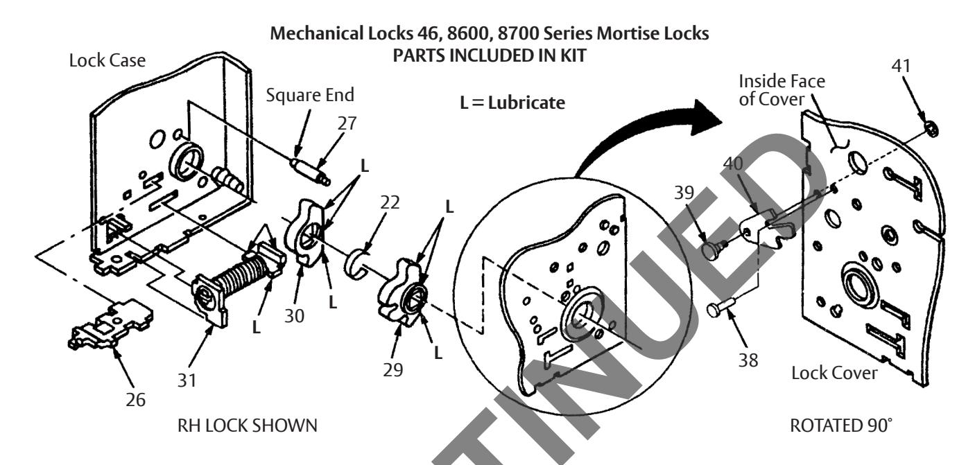
- Remove three screws from cover. Remove cover by lifting up and moving away from lock front. (Note position of all Internal components.)
- 2. Remove exsisting hubs and replace with new hubs 29 and 30, and 22 hub aligning ring. Be sure to place the locking hub 29 on the cylinder or locked side of the case. (Remove all foreign material and old lubricant from case. Use the lubricant packed with the kit to lubricate all areas noted with "L".)
- Insert the spring cage assembly 31. Align spring cartridge against hubs first, then compress spring and insert front into slots in case as shown.
- 4. Insert lever stop pin 27 in hole shown. Square end goes into hole in the case, tapered end acts as guide when installing cover.
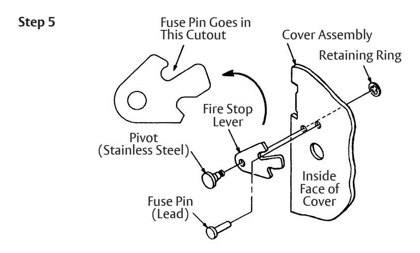
- 5. Assemble fire stop lever 40 to cover with pivot (stainless steel) 39 and its retaining ring 41 . Install fuse pin (lead) 38 and peen over as shown in illustration on page 3.
- Install new stop plunger 26 (note how old stop plunger is oriented in lock). New stop plunger is heat treated to with stand the added force that can be applied with the lever handle.
- 7. Replace cover. All parts must be in alignment with the positioning slots or openings in the cover. Do not force. Once the cover is firmly seated, insert and tighten three attaching screws.
- 8. Check lock to see that it operates properly.
- 9. Lock is now ready for installation in the door with new lever/spindle assembly.
IMPORTANT:
ALL STEPS MUST BE FOLLOWED EXPLICITY TO MAINTAIN UL LISTING OF THE LOCK ASSEMBLY.
MARNING
This product can expose you to lead which is known to the state of California to cause cancer and birth defects or other reproductive harm. For more information go to www.P65warnings.ca.gov.
MARNING
Attention Installer: Any retrofit or other field modification to a fire rated opening can potentially impact the fire rating of the opening, and ASSA ABLOY makes no representations or warranties concerning what such impact may be in any specific situation. When retrofitting any portion of an existing fire-rated opening, or specifying and installing a new fire-rated opening, please consult with a code specialist or local code official (Authority Having Jurisdiction) to ensure compliance with all applicable codes and ratings.
80-9086-0015-010 01/24
87FL Conversion Kit
For Mechanical Locks and Electrified Locks To Change from Knob Trim to Lever Trim Installation Instructions
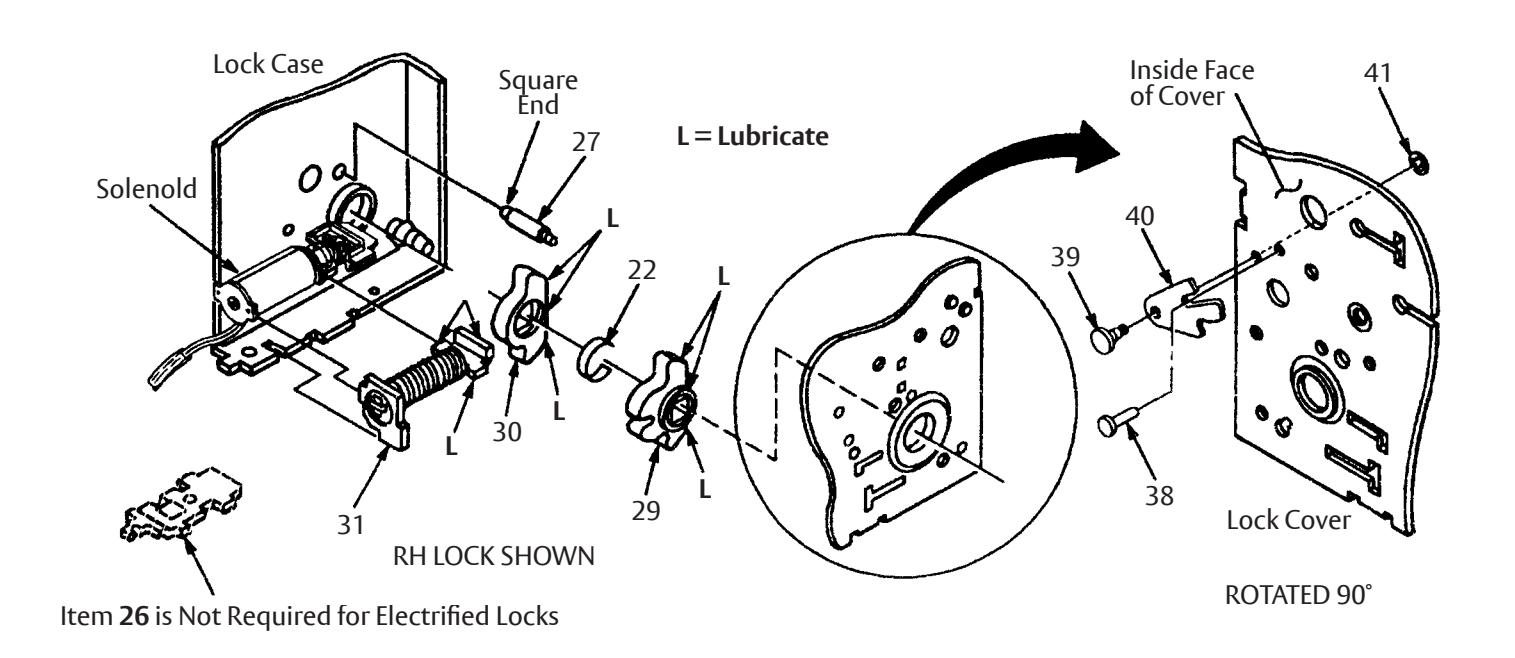
Electrified Locks 4680/90, 8680/90, 8780/90 Series Electric Mortise Locks 2600, 2700, 3100, 3900, 4100 Series Electronic Mortise Locks PARTS INCLUDED IN KIT
| Item No. | Part No. | Description | |
|---|---|---|---|
| 22 | 50-4601-1005 | Hub Aligning Ring | |
| 27 | 50-8700-1052 | Lever Stop Pin | |
| 29 | 50-4602-1004 | Lever Locking Hub | |
| 30 | 50-4601-1004 | Lever Hub | |
| 31 | 50-4601-0223 | Spring Cage Assembly | |
| 38 | 50-4601-6029 | Fuse Pin (Lead) | |
| 39 | 50-4601-7153 | Pivot (Stainlesss Steel) | |
| 40 | 50-4601-7028 | Fire Stop Lever | |
| 41 | 99-9999-4638 | Retaining Ring | |
| 42 | 99-9901-0100 | Lubricant | |
- 1. Remove three screws from cover. Remove cover by lifting up and moving away from lock front. (Note position of all Internal components. Pay particular attention to solenoid and stop plunger.)
- 2. Remove exsisting hubs and replace with new hubs 29 and 30 , and 22 hub aligning ring. Be sure to place the locking hub 29 on the cylinder or locked side of the case. (Remove all foreign material and old lubricant from case. Use the lubricant packed with the kit to lubricate all areas noted with " L ". Do not get lubricant on solenold plunger. )
- 3. Insert the spring cage assembly 31 . Align spring cartridge against hubs first, then compress spring and insert front into slots in case as shown.
- 4. Insert lever stop pin 27 in hole shown. Square end goes into hole in the case, tapered end acts as guide when installing cover.
- 5. Assemble fire stop lever 40 to cover with pivot (stainless steel) 39 and its retaining ring 41 . Install fuse pin (lead) 38 and peen over as shown in illustration on page 3.
- 6. Replace cover. All parts must be in alignment with the positioning slots or openings in the cover. Do not force. Once the cover is firmly seated, insert and tighten three attaching screws.
- 7. Check lock to see that it operates properly. (Be careful solenoid wires are not pinched or damaged by spring cage assembly 31 .)
- 8. Lock is now ready for installation in the door with new lever/spindle assembly.
IMPORTANT:
ALL STEPS MUST BE FOLLOWED EXPLICITY TO MAINTAIN UL LISTING OF THE LOCK ASSEMBLY.
80-9086-0015-010 01/24
87FL Conversion Kit
For Mechanical Locks and Electrified Locks To Change from Knob Trim to Lever Trim

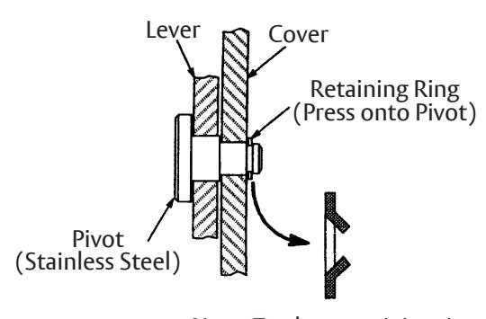
Note: Teeth on retaining ring are bent. Position so that ring is installed as shown.
ASSA ABLOY
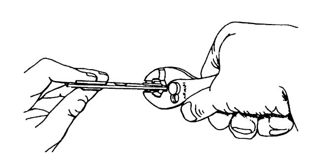
- 1. Assemble fire stop lever to lock cover with pivot (stainless steel) and retaining ring.
- Install fuse pin (lead) to hold lever in up position.
- Peen fuse pin (lead) with pliers. (Slip joint pliers in the open setting work well and prevent excessive compression of the pin.)
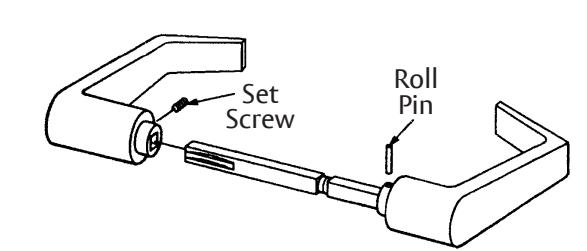
Lever Handles with Spindle
Inside Lever (Unlocked Side)
For Other Lever Handle Designs See Mortise Catalog
Outside Lever (Locked Side)
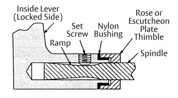
When installing levers be sure that swivel spindle is adjusted to allow turning and that ramp on spindle will be facing set screw. Tighten set screw securely using 1/8" hex key wrench.
80-9086-0015-010 01/24

Spindle Applications
1178L Swivel Spindles
|
4600, 8600, and 8700 Series
Mechanical and Electric Locks |
Electronic Locks
Cardcode, Touchcode, Guestcode, Guestlock |
||||
|---|---|---|---|---|---|
| Door Thickness | Spindle Length | Part No. | Door Thickness | Spindle Length | Part No. |
| 1-1/4" - 1-3/4" | 4.281 | 50-1178-0001 | 1-3/4" | 5.406 | 55-1178-0030 |
| 2" - 2-1/2" | 4.781 | 501178-0002 | 1-3/4 - 2-1/4" | 6.029 | 55-1178-0002 |
| 2-3/4" - 3-1/4" | 5.531 | 50-1178-0003 | 2-1/2" - 2-3/4" | 6.779 | 55-1178-0003 |
| 2-3/4 " - 3" | 7.529 | 55-1178-0004 | |||
The standard spindle furnished with the 87FL Kit is part no. 50-1178-0001. If a different spindle is required, specify part no. of spindle (i.e. CR87FL x 55-1178-0002 spindle).