ASSA ABLOY ACCENTRA 726 Strike for Vertical Rod Exit Devices Instructions_80-8470-0726-000
Open the original PDF document
View PDF726 Strike
Installation Instructions
| ABBREVIATION | FASTENER DESCRIPTION | |
|---|---|---|
| PFHMS | PHILLIPS FLAT HEAD MACHINE SCREW | |
| PRHMS | PHILLIPS ROUND HEAD MACHINE SCREW | |
All dimensions are in inches (mm) unless

This product can expose you to lead which is known to the state of California to cause cancer and birth defects or other reproductive harm. For more information go to www.P65warnings.ca.gov.
WARNING
80-8470-0726-000 04/24 Attention Installer: Any retrofit or other field modification to a fire rated opening can potentially impact the fire rating of the opening, and ASSA ABLOY makes no representations or warranties concerning what such impact may be in any specific situation. When retrofitting any portion of an existing fire-rated opening, or specifying and installing a new fire-rated opening, please consult with a code specialist or local code official (Authority Having Jurisdiction) to ensure compliance with all applicable codes and ratings.
1-855-557-5078 Ext. 2 • www.accentra-assaabloy.com
TAPE THIS TAB TO FRAME STOP 726 STRIKE
A
1-5/16 (33)
A
| Door | Fastener | Hole "A" |
|---|---|---|
|
Metal
Reinforced |
Screw | 1/4-20 Tap |
|
Hollow
Metal & Aluminum |
Optional
SBN |
5/16 (8) Dia.
Inside Door Face 3/8 (10) Dia. Outside Door |
|
All
Others |
SBN |
3/8 (10) Dia.
Thru Door |
TOP LATCH & STRIKE TAPE TO DOOR

CUT LINE
NOTES:
- 1. Mark Rods line on door face. Note that the centerline of the rods and strikes used to install top and bottom bolts, is not the Vertical Reference centerline.
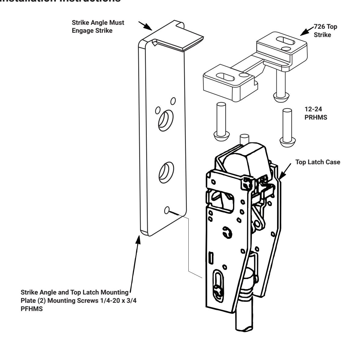
- 2. For LBR (Less Bottom Rod) Devices, omit bottom latch and strike installation and install 726 Top Strike with Strike Angle and "Popper" assembly supplied with device. Caution: LBR Devices should not be used where security is a primary concern.
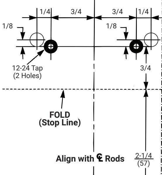
- 3. 726 Top Strike Installation: With door securely closed, tape template to door and frame stop. Spot and prepare holes for 726 top strike using (2) 12-24 Round Head Screws provided. With template still in-place, assemble upper mounting plate to door with the strike angle engaged into the 726 top strike, as shown below. Adjust hole locations for the mounting plate if required. Spot and prepare (2) outer holes then prepare (2) inner holes as designated on the template.
- 4. Unreinforced frames require that 12-24 blind rivet nuts (by others) be used to bolt strike. Frames are considered not reinforced when strike mounting screws cannot engage (3) full threads.
- 5. Dimensions are given in Inches (mm)
- 6. CAUTION: Office copiers and facsimile machines may change the size of a drawing and make the template inaccurate to use as a door marker.
80-8470-0726-000 04/24