ASSA ABLOY ACCENTRA 7130(F) Series Mortise Exit Devices Installation Instructions_80-9470-0030-000
Open the original PDF document
View PDF7130(F) Series Mortise Exit Devices
Installation Instructions

| Mortise Lock Chart | ||||||
|---|---|---|---|---|---|---|
| Function | Lock Number | |||||
| Panic Label | Fire Label | |||||
|
Exit Only
F02 F03 (Knob) |
35K | 35KF | ||||
| F03 (Lever) | 35L | 35LF | ||||
| F05 | 38T | 38TF | ||||
| F06 (Knob) | 38K | 38KF | ||||
| F08 (Lever) | 38L | 38LF | ||||
| ABBREVIATION | FASTENER DESCRIPTION | ||
|---|---|---|---|
| PPHMS | PHILLIPS PAN HEAD MACHINE SCREW | ||
| PRHMS | PHILLIPS ROUND HEAD MACHINE SCREW | ||
| FHPWMS | FLAT HEAD PHILLIPS WOOD/MACHINE SCREW | ||
| PUFHMS | PHILLIPS UNDER CUT FLAT HEAD MACHINE SCREW | ||
WARNING
This product can expose you to lead which is known to the state of California to cause cancer and birth defects or other reproductive harm. For more information go to www.P65warnings.ca.gov.
WARNING
Attention Installer: Any retrofi t or other fi eld modifi cation to a fi re rated opening can potentially impact the fi re rating of the opening, and ASSA ABLOY makes no representations or warranties concerning what such impact may be in any specifi c situation. When retrofi tting any portion of an existing fi re-rated opening, or specifying and installing a new fi re-rated opening, please consult with a code specialist or local code offi cial (Authority Having Jurisdiction) to ensure compliance with all applicable codes and ratings.
80-9470-0030-000 04/24

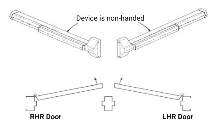
To Change Hand
For Metal Composite and Wood Doors Handed Mortise Lock
(See "To Change Mortise Lock Hand", below)
Maintenance
- 1. Periodically remove covers and coat mechanisms with a silicone base lubricant. This is particularly required in corrosive environments for proper product function.
- 2. Check mounting fasteners periodically. Retighten if found loose. Apply screw locking compound (available at automotive part stores) or change part fasteners if screws continue to back up.
Shim Kit Option
List Number: 723W Black Finish
Kit consists of Latch Head Shim (Device Cover seats on shim) and End Clamp Shim (End Cap seats on shim).
Each shim is 1/8 (3.2) thick. More than two Shim Kits require longer device mounting screws (not included).
1/4 Sex Nut Option
Recommended for unreinforced doors.
Specify Finish
| Device | Quantity | Size | Part Number | ||
|---|---|---|---|---|---|
| All (No Trim) | 4 |
1/4-20
66-0001-1745 |
|||
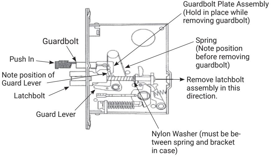
| To Change Mortise Lock Hand | All (With Trim) | 2 |
Typical Lock Body with Cover removed and showing only components relevant to lock handing. Other components vary according to function.
To change lock hand remove, flip latchbolt and guardbolt and reinstall.
80-9470-0030-000 04/24
7130(F) Series Mortise Exit Devices Installation Instructions

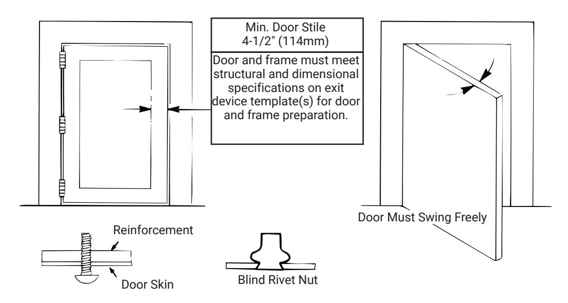
Check Before Starting
Unreinforced Doors or Frames
Doors and Frames with walls having a structural thickness (metal skin plus reinforcement or solid hardwood) to engage less than (3) full screw threads are considered unreinforced.
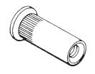
Unreinforced Doors: Use SNB (sex nuts and bolts).
Unreinforced Frames: Use Blind Rivet Nuts.
Recommended fasteners for unreinforced openings are not necessarily supplied by ASSA ABLOY Security, Inc.
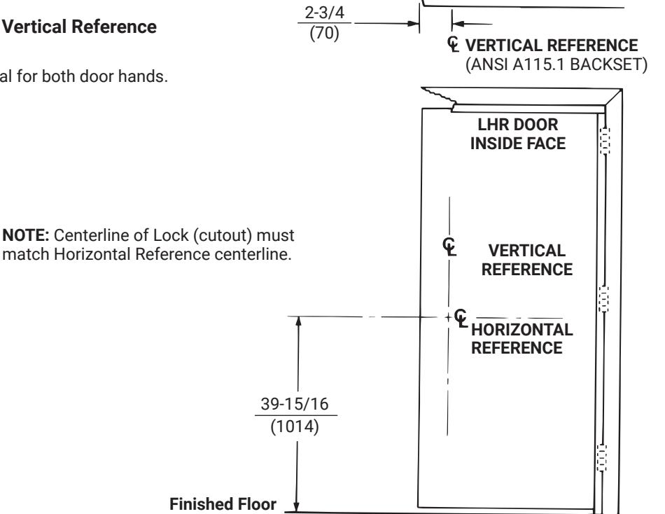
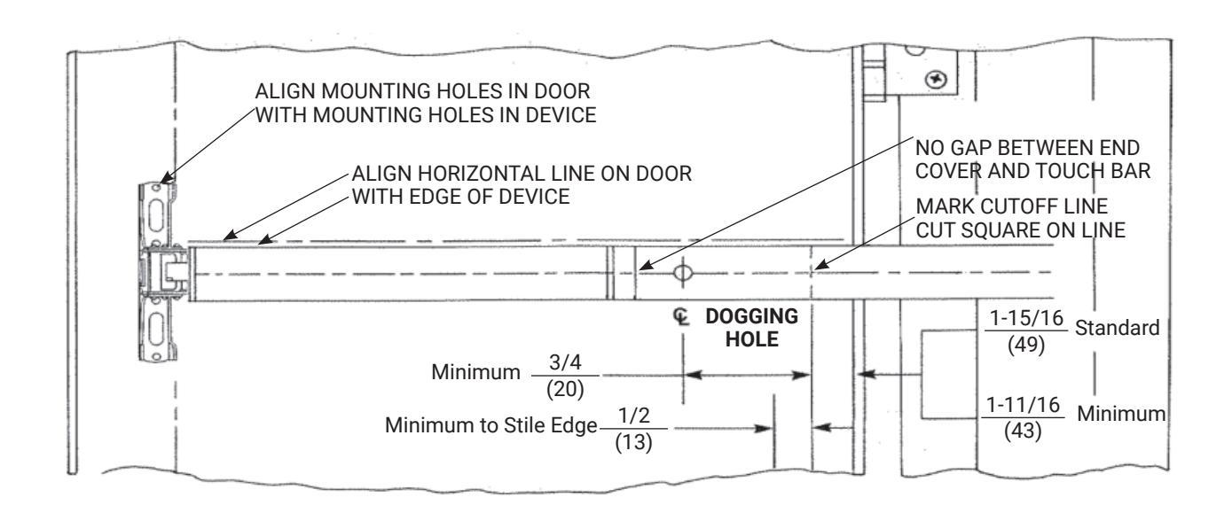
1. Mark Door
Locate and Mark Horizontal and Vertical Reference Centerlines as shown.
LHR door shown preparation is typical for both door hands.
80-9470-0030-000 04/24
DOOR, LOCK, AND STRIKE

2. Prepare Door and Frame
Factory prepared cutouts with field drilled mounting holes are recommended. If door (lock) and frame (strike) have to be mortised in the field, do it before continuing (follow instructions on Installation Template).
Spot and Prepare Mounting Holes as Follows:
- A. Locate and tape Trim Template to door. (See instructions packed with Trim.)
- B. Locate "Device Template" aligning VERTICAL REFERENCE and HORIZONTAL REFERENCE lines on door and template. Tape template to door face.
- (1) Slot 1/2" (12.7) Dia. x 1" (25.4) on centers thru inside door face and (2) Device holes for 1/4-20 Machine Screws*, or for 3/8" (9.5) Dia. Sex nuts and Bolts.
- (*) Metal reinforced doors only.
-
C. Insert lock into mortise, adjust front for door edge (beveled or flat)*. Lock holes for 12-24 Machine Screws or for #12 Wood Screws.
- NOTE: Lock base front has to be field tightened in place, (two screws, each on lock case top and bottom).
-
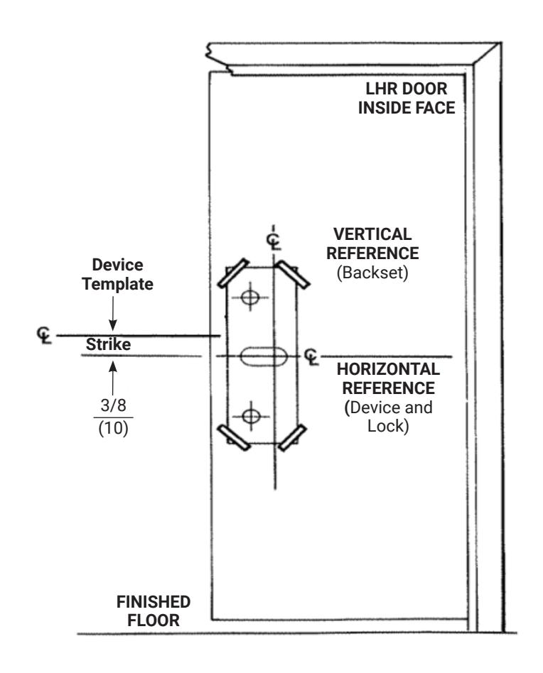
D. Seat strike in frame cutout.
- (2) Strike holes for 12-24 Machine Screws, or for #12 Wood Screws.
prohibited.
Reproduction in whole or in part without the express written permission of ASSA ABLOY Access and Egress Hardware Group, Inc. is

3. Size Device
Device must be field cut to size, unless standard opening and device are 36" (0.91m).
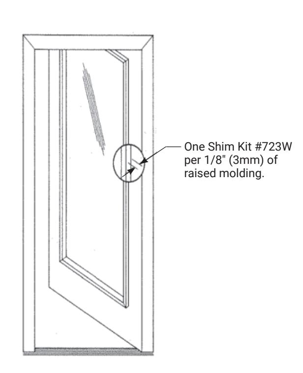
4. Clear Raised Door Molding
Device must seat flush on door surface, or on shims that keep it parallel to door face.
One Shim Kit #723W required for each 1/8" (3mm) of device lift needed. Two Shim Kits Maximum for standard device in 1-3/4" (44) door. For thicker doors, consult the factory.
80-9470-0030-000 04/24

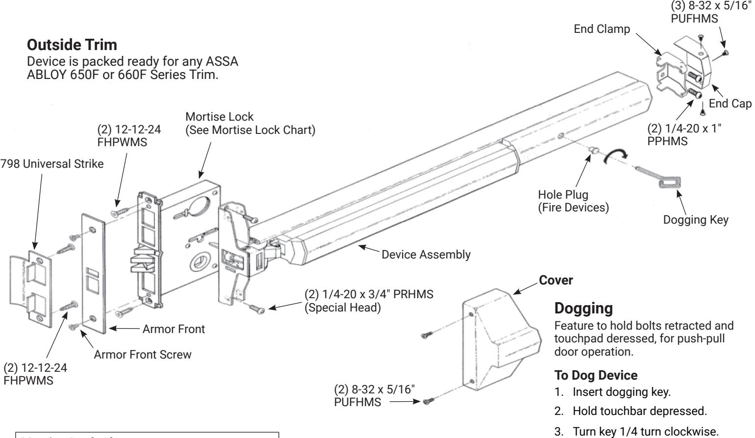
5. Install Components
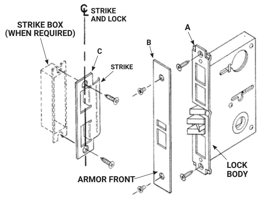
A. Install Lock
Lock in hand, depress guardbolt. Check that latchbolt is deadlocked.
Check that latchbolt lever (and cylinder lever, hubs, and thumbpiece lever, if relevant) operate the lock freely.
Insert Lock Body into door cavity. Fasten to door edge (2 FHPWMS)
NOTE: Make sure that door reinforcing clips or doorwalls support lock immovable (restricting rocking motion).
B. Install Armor Front
Fit over bolts and fasten to lock base front (2 PUFHMS). Check that bolts retract and extend freely.
C. Install Strike
Seat in place (lip bend away from opening). Fasten to frame (2 FHPWMS).
D. Install Trim
Follow instructions packed with trim.
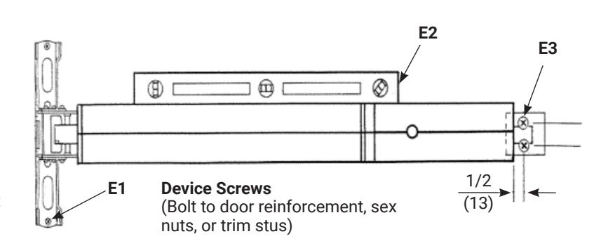
E. Install Device
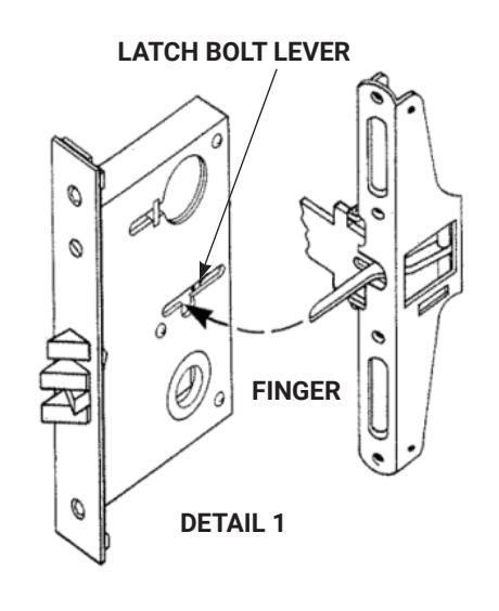
Seat Bar in place (Device finger must engage latchbolt lever, thru slot in lock case/cover, as shown in Detail 1). Fasten Device Head (2 PRHMS or SNB).
Set Bar level. Locate End Clamp holes.
Prepare end Clamp mounting holes. Fasten End Clamp in place.
F. Check Operation
Depress touchbar (bolt must retract). Release touchbar (bolt must extend).
- Actuate trim (bolt must retract). Release trim actuator (bolt must extend).
- 2. (NOT FOR FIRE DEVICES). Depress touchbar, turn dogging key clockwise (bar must remain depressed, bolt must remain retracted). Turn dogging key counterclockwise (bar and bolt must return to extended position).
- Close door. Latchbolt should fully engage into strike cavity, guardbolt should retract over strike ramp. Door should not rattle.
NOTE: When resulting operation if faulty, check first for visible binding or interference. If there is no apparent reason for the fault, remove item from the door and recheck its operation before assuming that it is defective.
G. Tighten all mounting screws.
80-9470-0030-000 04/24
Experience a safer and more open world
1-855-577-5078 Ext. 2 • www.accentra-assaabloy.com

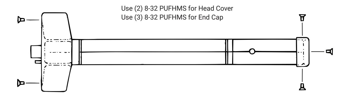
6. Install Head Cover and End Cap