ASSA ABLOY ACCENTRA 7116 Alarm Kit Installation for 7000 Series Exit Device (For units shipped prior_80-9470-7116-000
Open the original PDF document
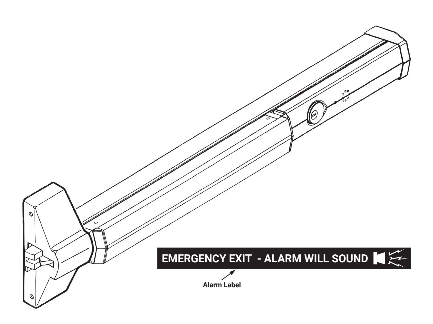
View PDF7000-A Series Alarm Exit Devices 7116 Alarm Retrofit Kit
Installation Instructions
WARNING
This product can expose you to lead which is known to the state of California to cause cancer and birth defects or other reproductive harm. For more information go to www.P65warnings.ca.gov.
WARNING
Attention Installer: Any retrofit or other field modification to a fire rated opening can potentially impact the fire rating of the opening, and ASSA ABLOY makes no representations or warranties concerning what such impact may be in any specific situation. When retrofitting any portion of an existing fire-rated opening, or specifying and installing a new fire-rated opening, please consult with a code specialist or local code official (Authority Having Jurisdiction) to ensure compliance with all applicable codes and ratings. 80-9470-7116-000 04/24

7116 Alarm Retrofit Kit Installation Instructions
EXIT ALARM INSTRUCTIONS
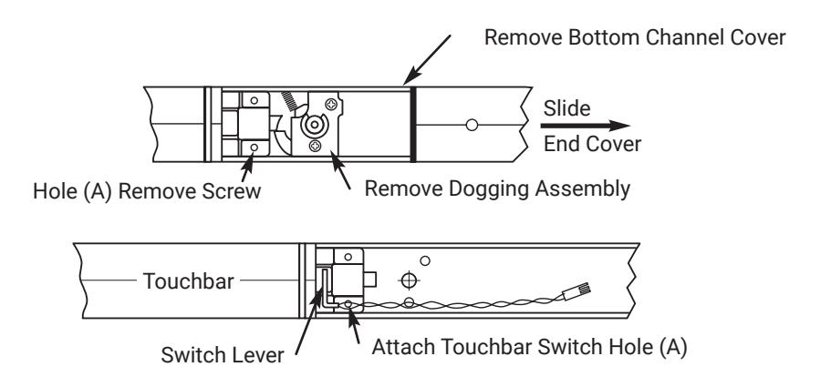
1. Install Touchbar Switch Retrofit Applications
- 1. Remove Device from door.
- 2. Remove End Cover and black End Plate. Discard End Plate.
- 3. If Device has dogging, remove dogging assembly with (2) screws.
- 4. Remove Bottom Channel Cover from Device.
- 5. Locate rear touchbar mounting hole (A) as indicated below. Remove screw, if one is assembled, and install in opposite hole.
- 6. Remove screw from Touchbar Switch Bracket and align screw hole over touchbar mounting hole (A).Reinstall screw from bottom of channel to secure. Switch Bracket.
- 7. Verify that moving the touchbar causes the switch to trip. Adjust switch lever as required.
- 8. Replace Bottom Channel Cover.
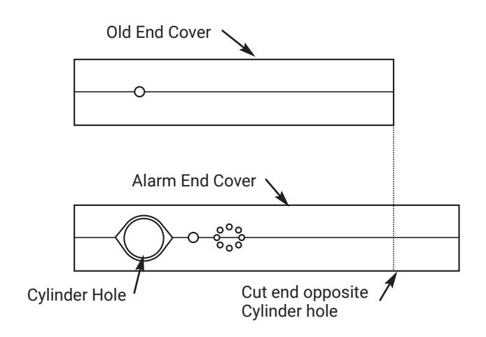
2. Size End CoverOnly - All Except SVR
- 1. For New installations, follow procedures in Device installation instructions.
- 2. For RETROFIT applications, cut new Alarm End Cover to same length as old End Cover.
- 3. Cut Alarm End Cover on end opposite Cylinder hole as shown.
NOTE: Cover can be cut to a minimum length of 9-1/4" (235 mm)
80-9470-7116-000 04/24
7116 Alarm Retrofit Kit Installation Instructions

3. Assemble Alarm End Cover
- Slide Alarm Housing Assembly into Alarm End Cover, making sure tabs are engaged and LED is inserted into lens.
- Insert Cylinder, with Ring if required, into Alarm End Cover aligning cylinder grooves with locating tabs on housing assembly. NOTE: Cylinder keyway to be positioned towards Touchbar.
- Install Arming Switch Activator over Cylinder so that Activator legs are on each side of toggle switch.
- Secure parts with Alarm Cylinder Nut, making sure Activator rotates freely. Check that rotating the key causes Activator to trip switch in both directions.
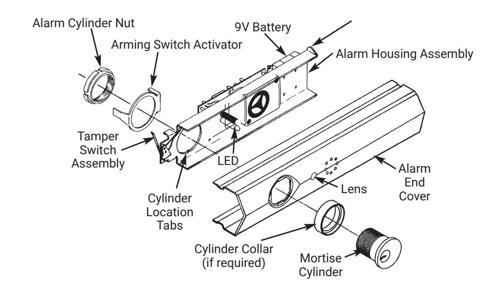
4. Install Alarm Assembly
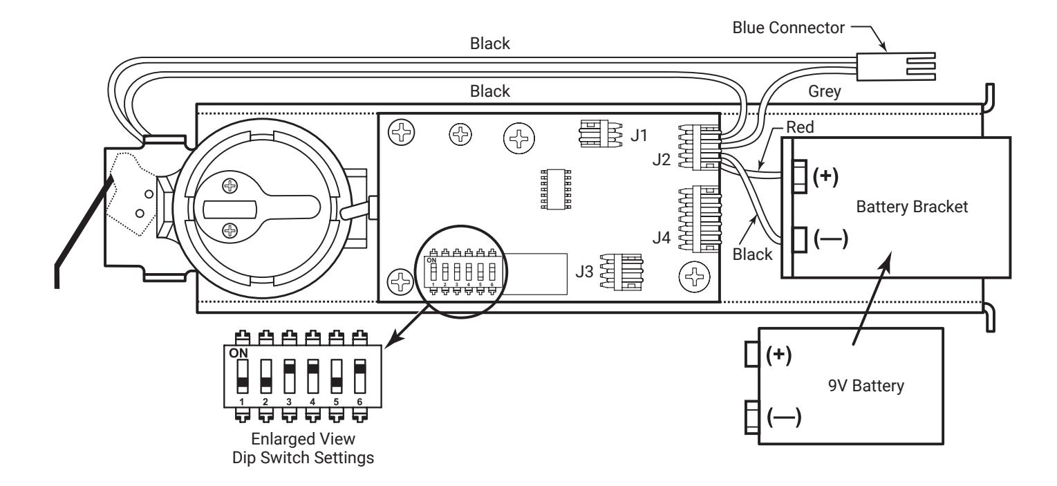
- Install 9V Battery with correct polarity. Verify all connections and switch settings. (See Tables 1, 2 and 3 on Page 5).
-
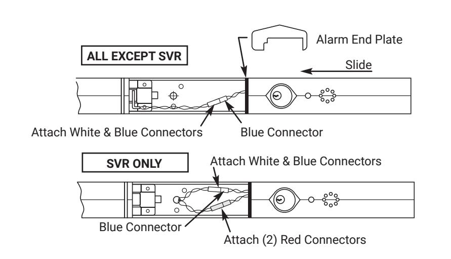
2. ALL EXCEPT SVR
- a. Attach white & blue connectors.
- b. SVR FACTORY-WIRED ONLY: Attach white & blue connectors and (2) red connectors.
- Install Alarm End Plate while sliding Alarm End Cover onto Device. Make sure wires are not pinched or cut.
- 4. Install Device on door and check alarm functions.
- Install Alarm Label on Touchbar or on door above device.
80-9470-7116-000 04/24

7116 Alarm Retrofit Kit Installation Instructions
ALARM FUNCTION AS SHIPPED
- 1. Upon arming, LED will flash AMBER and the device will allow egress without triggering alarm for 20 seconds.
- 2. After 20 seconds, alarm will chirp one time and the device will be ARMED .
- 3. The LED will flash RED every 30 seconds, indicating the device is ARMED .
- 4. Once the device is ARMED, egress will result in an alarm sound that will stop only when the device is RE-ARMED by key or remote.
- 5. Low Battery Indicator Alarm will chirp every 30 seconds, indicating battery needs to be replaced.
NOTE:
- y Alarm PC Board has Dip Switches DS-1, 2, 3, 4, and 5 factory preset per Tables 1, 2, and 3 shown on Page 5.
- y Dip Switch DS-6 is for "hard wire" configurations and setting does not affect stand-alone battery operation.
7000-A Series Alarm Exit Devices 7116 Alarm Retrofit Kit Installation Instructions

| REX and Passage Time Delay | |||
|---|---|---|---|
| When the device is initially ARMED by key, the LED | |||
| will flash AMBER and allow egress for a time defined | |||
| in Table 1. | |||
| TABLE 1 | ||
|---|---|---|
| DS-1 | DS-2 | Timer Delay |
| *Off | *Off | 7 Seconds |
| Off | On | 10 Seconds |
| On | Off | 15 Seconds |
| On | On | 20 Seconds |
Automatic Alarm Reset
The alarm can be set so that it will reset itself after a violation has occurred per Table 2. If the device automatically resets, the indicator light will flash GREEN every 30 seconds instead of RED to indicate a violation has occurred.
| TABLE 2 | ||
|---|---|---|
| DS-3 | DS-4 | Reset Time |
| Off | Off | 2 Minutes |
| Off | On | 5 Minutes |
| On | Off | 10 Minutes |
| *On | *On | No Auto Reset |
| Armed and Violation LED Color Selection | |||
|---|---|---|---|
| Device is shipped standard, per Table 3, so that RED LED | |||
| flashes every 30 seconds when device is ARMED, and | |||
|
flashes GREEN every 30 seconds under auto reset, when
door has been violated. |
|||
| TABLE 3 | ||
|---|---|---|
| DS-5 | Armed LED Color |
Armed Violation
LED Color |
| *Off | Red | Green |
| On | Green | Red |
* Factory Preset

7116 Alarm Retrofit Kit Installation Instructions
| Problem | Solution |
|---|---|
| y Alarm will not sound |
y Battery is not connected.
y Battery needs replacing. y Alarm in not ARMED. Turn key clockwise. |
| y Alarm sounds when keyswitch is activated. |
y Touchbar Switch is not installed correctly. Verify that switch
opens when Touchbar is depressed, and closes when Touchbar is released. Position switch lever as necessary. y Tamper Switch is not closing when Alarm End Cover is installed. Make sure cover is installed completely. y Touchbar is bound and not traveling smoothly. Check by pulling on Touchbar and arming. y J2 connector not installed, or loose. |
| y Alarm chirps every 30 seconds. | y Low battery indicator, replace battery. |
| y ARMED indicator LED, wrong color |
y Change position of DS-5 Dip Switch.
"OFF" for RED ARMED indicator. "ON" for GREEN ARMED indicator. |
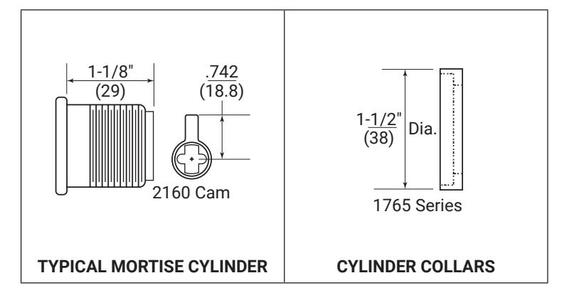
Cylinders and Collars
Use standard 1-1/8" mortise cylinder with 2160 cam. Number 2153 x 1-1/8" cylinder. Cylinder Collar is not required. Cylinder Collars are required for use with cylinders longer than 1-1/8".
Copyright © 2012, 2023, 2024, ASSA ABLOY ACCENTRA™ Access and Egress Hardware Group, Inc. All rights reserved. Reproduction
80-9470-7116-000 04/24
6
7000-A Series Alarm Exit Devices 7116 Alarm Retrofit Kit Installation Instructions