ASSA ABLOY ACCENTRA 7116 Alarm Kit Installation for 7000 Series Exit Device (For units shipped after_80-9470-7116-010
Open the original PDF document
View PDFInstallation Instructions
These instructions pertain to 7116 alarm assemblies shipped after October 2012. For units shipped prior, please refer to 80-9470-7116-000. See section A for instructions on updating an alarm assembly shipped prior to October 2012. See section B for installation instructions for where an existing alarm assembly is not present.
Section A
The following instructions should be used when updating an existing alarm assembly.
Existing Touchbar Switch Disassembly
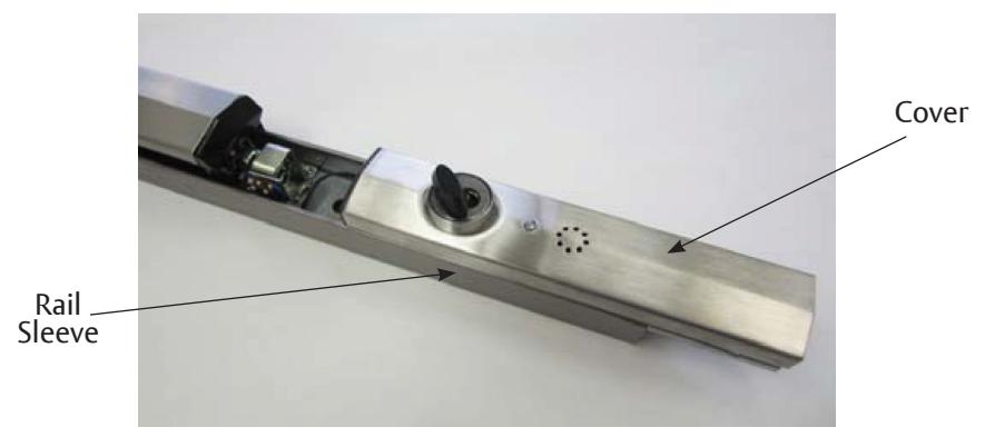
1. After removing device from door, slide existing alarm cover and rail sleeve out (Figure 1).
Figure 1
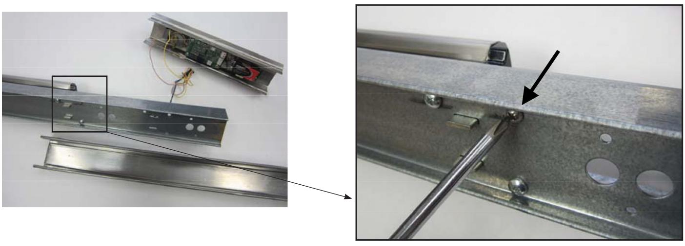
2. After removing the existing cover and sleeve, unscrew the one screw shown on Figure 2.
Figure 2
WARNING
This product can expose you to lead which is known to the state of California to cause cancer and birth defects or other reproductive harm. For more information go to www.P65warnings.ca.gov.
WARNING
Attention Installer: Any retrofit or other field modification to a fire rated opening can potentially impact the fire rating of the opening, and ASSA ABLOY makes no representations or warranties concerning what such impact may be in any specific situation. When retrofitting any portion of an existing fire-rated opening, or specifying and installing a new fire-rated opening, please consult with a code specialist or local code official (Authority Having Jurisdiction) to ensure compliance with all applicable codes and ratings.
80-9470-7116-010 12/23
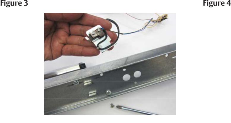
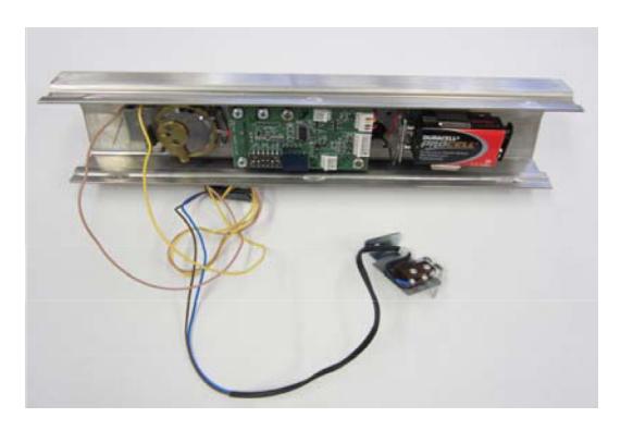
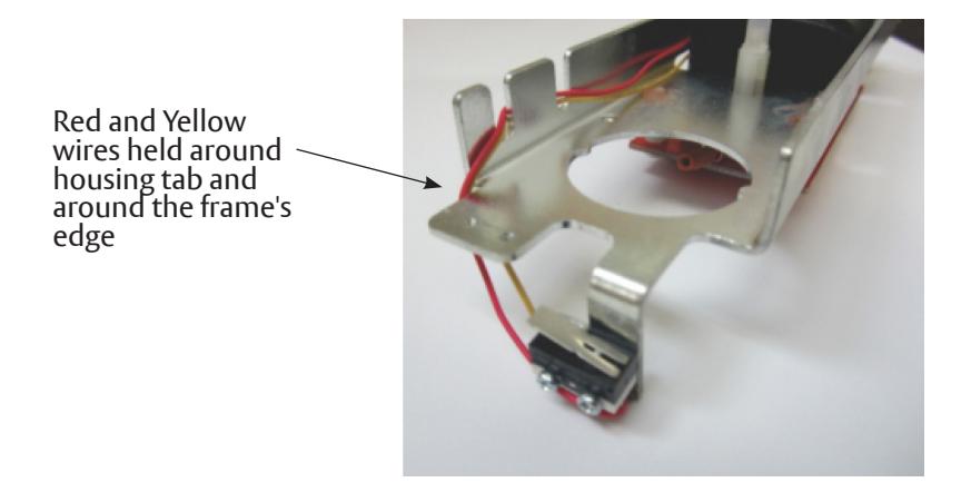
3. Remove the touchbar switch (Figure 3), which will be wired to the existing alarm cover assembly as shown below (Figure 4). Discard the screw.
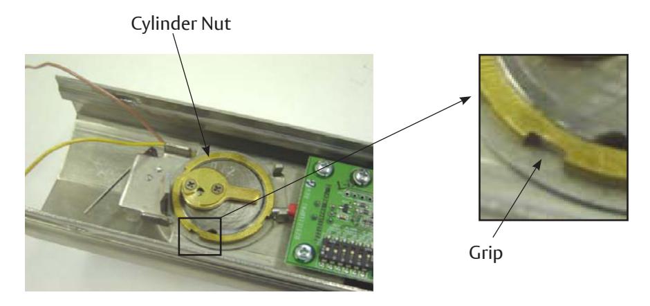
4. Remove the cylinder nut by turning counter-clockwise using the provided grips (Figure 5). You may use a flat screwdriver, tapping it with a hammer until loose enough to turn with fingers.
Figure 5
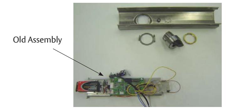
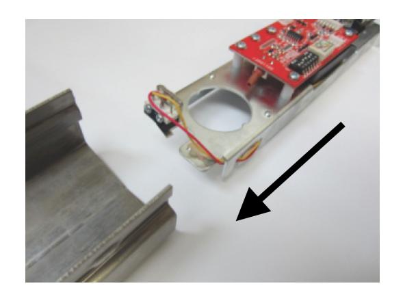
5. Discard the old alarm assembly. Save the cover, the cylinder, and the parts that hold the cylinder in place (Figure 6). These last items may not be provided with the new alarm kit.
Figure 6
6. Slide the rail sleeve back on and re-install the exit bar to the door. Now you are ready to install the new alarm assembly. See Section B.
80-9470-7116-010 12/23
ASSA ABLOY
Installation Instructions
Section B
The following instructions should be used for installation where an existing alarm assembly is not present.
Components
Figure 7
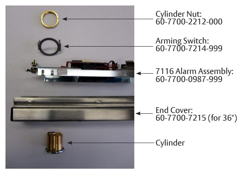
Figure 8
Alarm Cover Assembly (60-7700-0984-xxx)
1. Inspect the alarm board assembly to make sure wires are routed as shown in Figure 9.
Figure 9
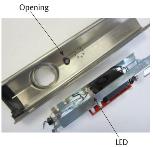
2. Slide the alarm board assembly into the cover as shown in Figure 10. Make sure the LED aligns with the opening on the cover.
Figure 10 Figure 11
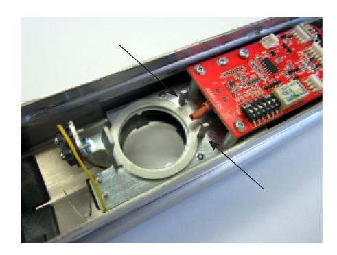
3. Position the arming switch over the cylinder opening as shown on Figure 12. Make sure the alarm's toggle switch is between the two posts as shown.
Figure 12
Installation Instructions
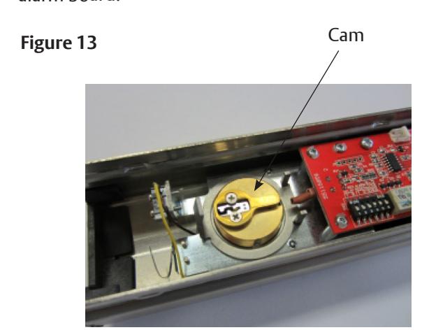
4. Holding the Arming switch in place, insert the cylinder as shown on Figure 13. Make sure the cam is pointing towards the alarm board.
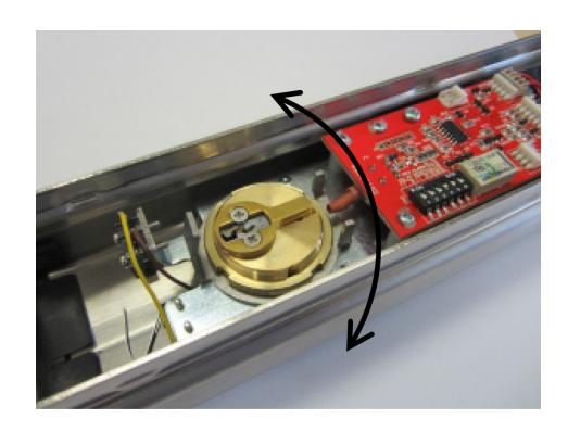
5. Secure the cylinder with the cylinder nut. Make sure the lip of the nut is facing up (Figure 14) and the arming switch is free to rotate after the cylinder is secured (Figure 15)
Figure 14 Figure 15 Lip
Switch Activator Installation
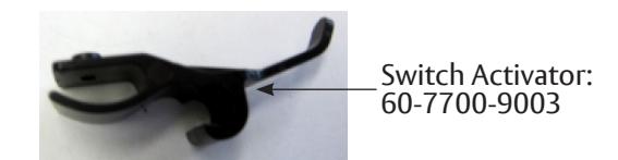
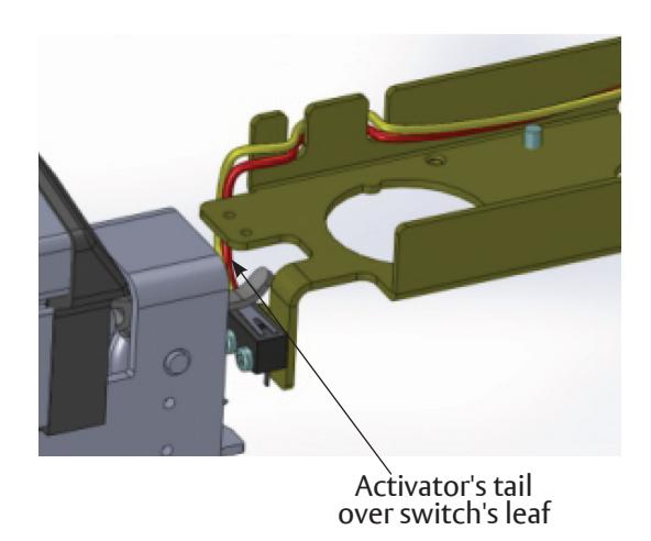
6. Install the switch activator making sure it's secure on the flange and the pin of the bar mechanism (Figure 17). The Activator tail should move up when the bar is depressed.
Figure 16 Figure 17 Figure 18
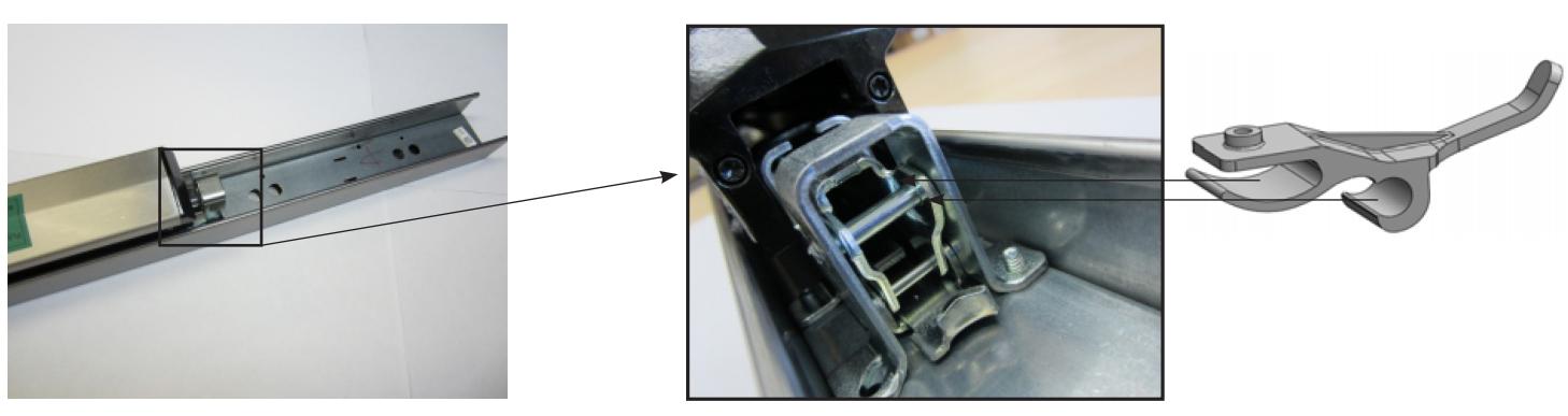
Figure 19
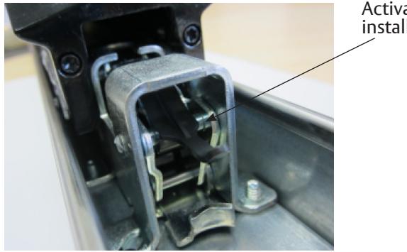
Activator installed
Cover Installation
7. Take the alarm cover (60-7700-0984-xxx ) as completed in Section B and slide it into the rail as shown in Figure 20. Make sure the activator's tail slide over the alarm switch (Figure 21).
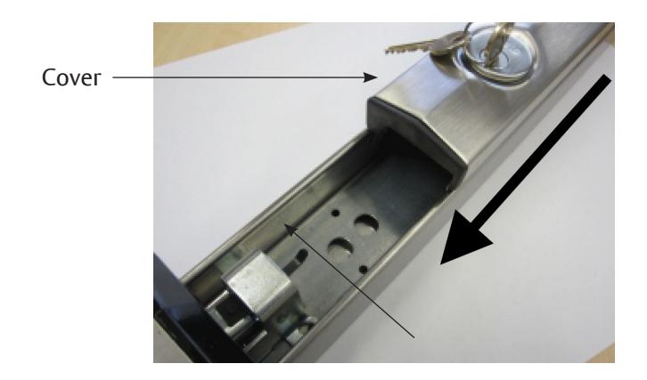
Figure 20 Figure 21
80-9470-7116-010 12/23

Installation Instructions
Battery Installation
8. Install 9V battery as shown in Figure 22. Make sure it's well secured in the battery holding bracket.
Figure 22

9. Test the alarm:
- a. Rotate key clockwise to arm the alarm. Wait 20 sec. for the confirmation chirp.
- b. Depress the touch pad. The alarm should be activated by this act.
- c. Turn key counter-clockwise to turn the alarm off.
- d. Rotate key clockwise to arm the alarm. Wait 20 sec. for the confirmation chirp.
- e. Slide the cover out with the intention to remove it. The alarm should be activated by this act.
- f. Turn key counter-clockwise to turn the alarm off.
- g. If there were problems activating the alarm refer to Troubleshooting.
- h. If the alarm was activated successfully on steps 9.b and 9.e, the test is completed.
Troubleshooting
-
1. Wires and Switches
- a. If the wires are loose or not routed correctly, please re-route using Figure 9 as a reference before installation.
- b. If wires or switch leafs are broken the alarm assembly has to be replaced before installation.
-
2. Arming Switch Not Rotating
- a. If the arming switch is not free to rotate the nut may be upsidedown. Make sure the "lip" is up to prevent compression on the arming switch.
- b. If the arming switch is not free to rotate, yet the nut is correctly installed, loosen up the nut 1/4 of a turn. Check the arming switch again.
-
3. Switch Activator Out of Position
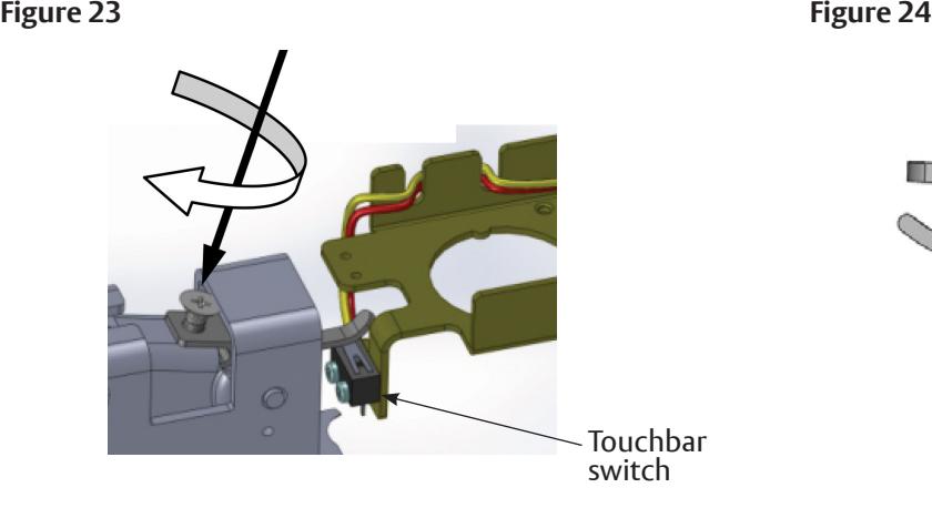
- a. If the tail of the switch activator is lower than the Touchbar switch, carefully pull up the tail by hand until it is slightly above the switch. Lift gently to prevent damage to either the switch or the activator arm.
- b. If the tail of the switch activator is too high to make contact with the Touchbar switch, insert a thread forming screw M2.5 x 5 as shown in Figure 23. Turn the screw as needed in order to lift the front of the activator off the metal; this should lower the tail enough to ensure proper switch contact (Figure 24).
-
4. Alarm Will Not Sound
- Battery not well connected.
- Battery needs to be replaced.
- Alarm is not armed. Turn key clockwise.
-
5. Alarm Sounds when Keyswitch is Activated
- Activator may not be installed correctly. Refer to Troubleshooting step 3.
- Tamper switch (Figure 23) may not be closing when alarm end cover is installed. Make sure the leaf is being depressed by the mechanism frame as shown on Figure 21.
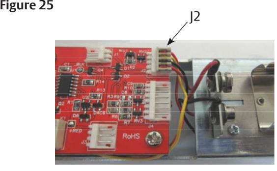
- J2 connector may be disconnected or loose (see Figure 25).
-
6. Alarm Chirps Every 30 Seconds
- Low battery indicator, replace battery.
Note: For other issues, please refer to Installation Instructions 80-9470-7116-000.