ASSA ABLOY ACCENTRA 680F, 681F, and 684F Offset Pull Trim Installation Instructions_80-8470-0680-000
Open the original PDF document
View PDF680F, 681F and 684F Exit Device
Trim
Installation Instructions

For use with 7100 Series Exit Device (Wood and Metal Doors)
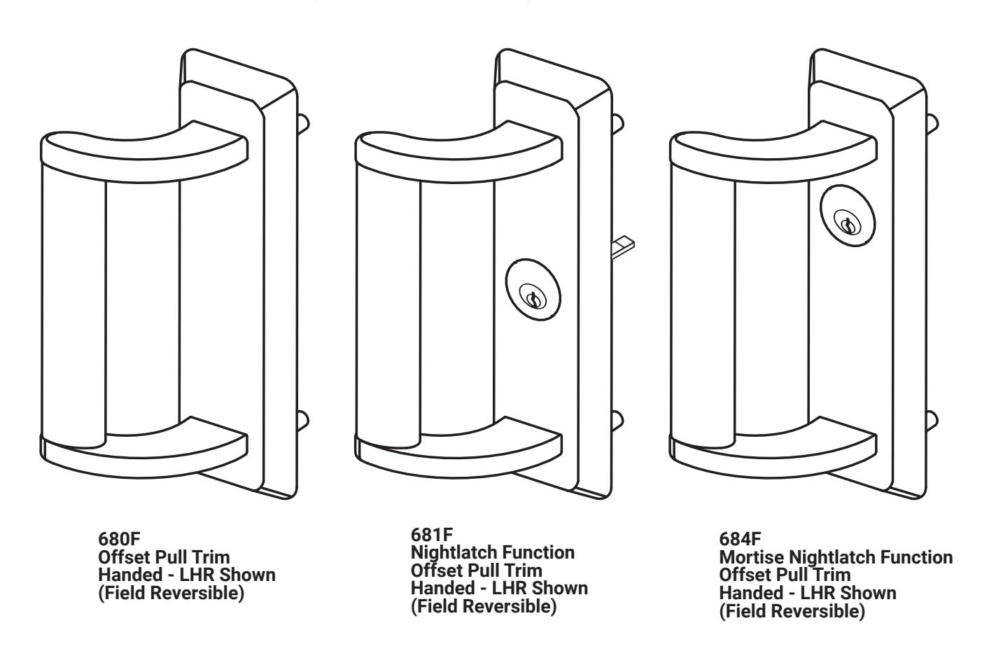
For Handing, see "Trim Assembly" on page 2.

This product can expose you to lead which is known to the state of California to cause cancer and birth defects or other reproductive harm. For more information go to www.P65warnings.ca.gov.
⚠ WARNING
Attention Installer: Any retrofit or other field modification to a fire rated opening can potentially impact the fire rating of the opening, and ASSA ABLOY makes no representations or warranties concerning what such impact may be in any specific situation. When retrofitting any portion of an existing fire-rated opening, or specifying and installing a new fire-rated opening, please consult with a code specialist or local code official (Authority Having Jurisdiction) to ensure compliance with all applicable codes and ratings.
1-855-557-5078 Ext. 2 • www.accentra-assaabloy.com
Experience a safer and more open world

680F, 681F and 684F Exit Device Trim
Installation Instructions
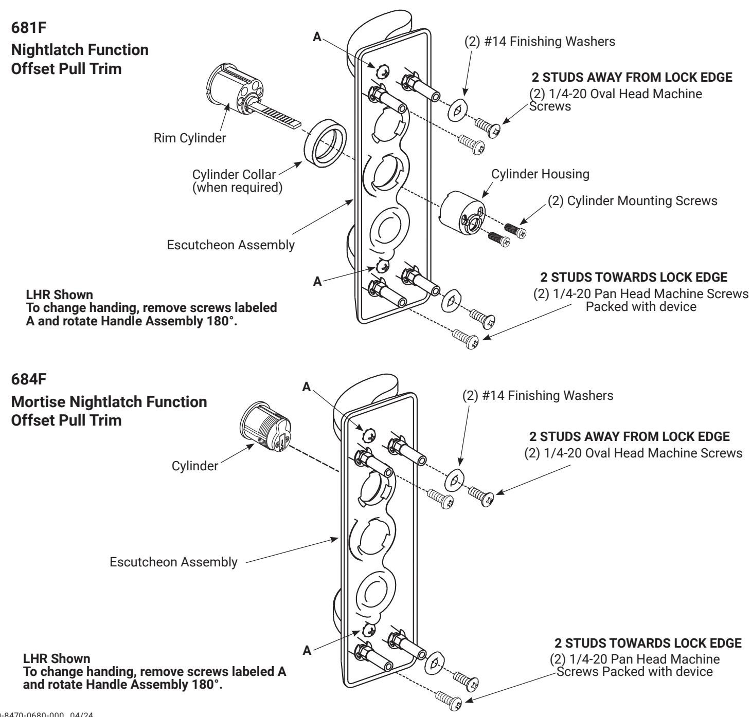
Trim Assembly
1. Check cylinder components.
Note: Refer to ASSA ABLOY cylinder chart in catalog for collar sizing.
-
2.
Assemble cylinder.
- a. Insert cylinder housing prongs into matching notches of escutcheon. Pass cylinder tailpiece thru cylinder collar (when required) and hole in cylinder housing.
- b. Fasten cylinder using (2) mounting screws. DO NOT OVERTIGHTEN SCREWS.
80-8470-0680-000 04/24
1-855-557-5078 Ext. 2 • www.accentra-assaabloy.com
680F, 681F and 684F Exit Device
Trim
Installation Instructions
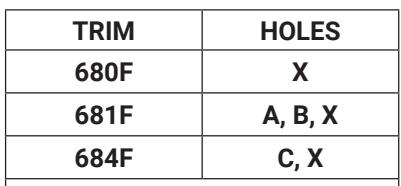
For Holes Marked X See Below
METAL DOORS
Inside Face: 5/16" (8) Dia. Outside Face: 1/2" (13) Dia.
WOOD DOORS
1/2" (13) Dia. Thru
Dimensions given in Inches (mm)
Caution: Office copiers and facsimile machines may change the size of a drawing and make the template inaccurate to use as a door marker. If this is not the original template packed with the trim, use only the holes on the door (do not use template as a door marker).
| (17) |
(17)
X |
||
| C | |||
| CL | |||
|
1/2
(13) B Dia. Thru |
VERTICAL
REFERENCE |
CUT LINE | |
| 11/16 |
X
11/16 |
||
| 11/16 |
11/16
A |
1-1/2 (38) Dia.
1-1/4 (32) Deep 1-1/2 (38) Dia. 1-1/4 (32) Deep HORIZONTAL REFERENCE (Device and Trim) (Device and Trim) (17) (17) |
80-8470-0680-000 04/24

Installation Instructions
- 1. Check box for contents. See page 2 for components.
- 2. After marking door inside face for device location (Device Instructions), transfer Vertical Reference Centerline from inside to outside door face. Follow steps a and b below.
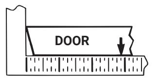
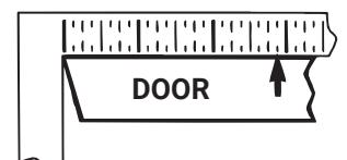
- a. MEASURE INSIDE LINE LOCATION.
- b. TRANSFER DIMENSION TO OUTSIDE FACE.
- 3. Transfer Horizontal Reference Centerline from inside to outside door face.
- 4. Align trim template and tape to outside door face.
- 5. Spot holes and prepare door for trim.
- 6. Mount trim to door thru holes B. Fasten finger tight only with (2) screws and washers seating on door as shown in Figure 1.
-
7. Continue according to trim type:
-
For 681F Nightlatch Trim: Cut trim tailpiece as shown in
Figure 2. Seat device so that the trim tailpiece
- Figure 2. Seat device so that the trim tailpiece penetrates cam slot as shown in Figure 1.
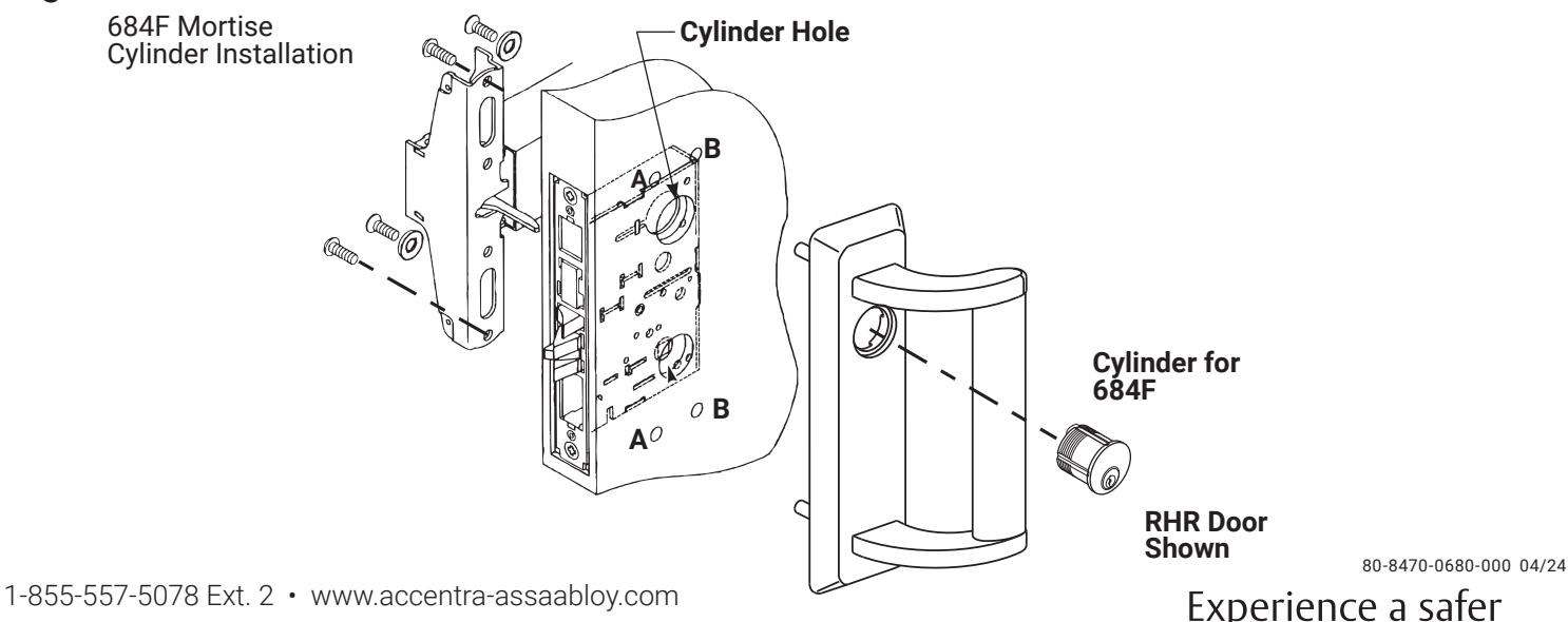
- For 684F Mortise Nightlatch Trim: Insert and thread cylinder into Mortise Lock until seated within escutcheon recess with keyway positioned vertically and with plug in lower cylinder as shown in Figure 3. Tighten cylinder locking screw thru mortise lock front.
-
For 681F Nightlatch Trim: Cut trim tailpiece as shown in
Figure 2. Seat device so that the trim tailpiece
- 8. Continue as shown in device instructions.
Figure 1
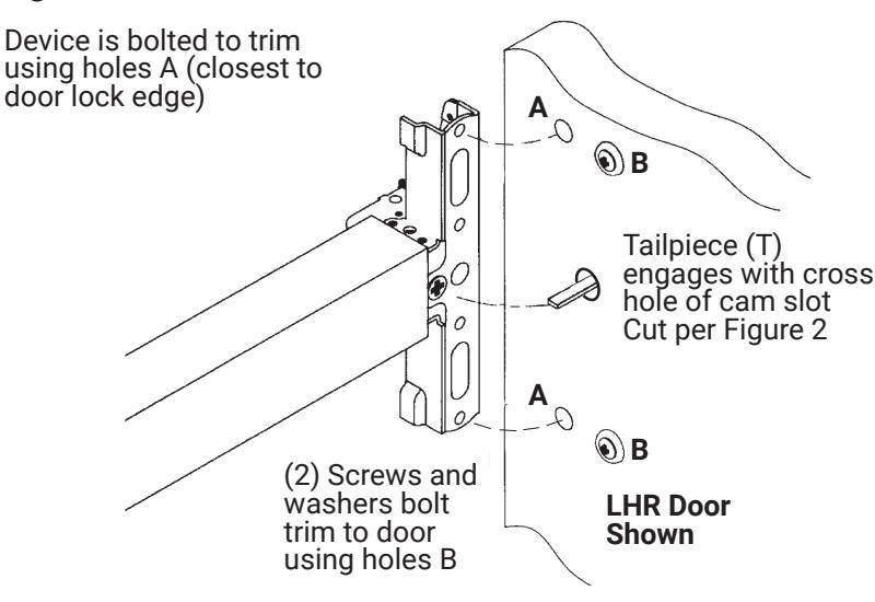
Figure 2
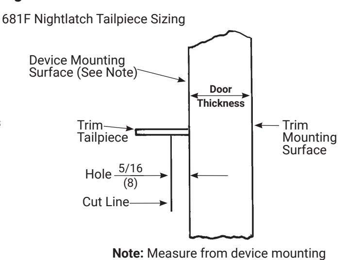
surface (door face or shim surface)
Figure 3
Copyright © 2023,2024, ASSA ABLOY ACCENTRA™ Access and Egress Hardware Group, Inc. All rights reserved. Reproduction in whole or in part without the express written permission of ASSA ABLOY Access and Egress Hardware Group, Inc. is prohibited.
Experience a safer and more open world