ASSA ABLOY ACCENTRA 6400LN Series Cylindrical Locks Monolock Replacement Installation Instructions_80-9260-0007-010
Open the original PDF document
View PDF6400LN Series Monolock Replacement
Installation Instructions
Tools Required
- 2-1/8" (54mm) hole saw
- 5/16" (8mm) drill bit
- 7/64" (2.5mm) drill bit
- Chisel & hammer
- 3/8" or 1/2" drill
- #2 Phillips screw driver
- 1" (26mm) boring bit
- Handle removal tool (supplied)
1. Drill Door (if necessary)
Refer to template 7150-2001 for door prep cut out.
- 1. Drill 2-1/8" (54mm) dia. Hole (A) and (2) 5/16" (8mm) holes (B) through door.
- 2. Cut 1-3/4" (44.5) slot (C) through from edge of door into 2-1/8" (54mm) hole.
- 3. Cut notch (D) at back of 2-1/8" (54mm) hole inside and outside.
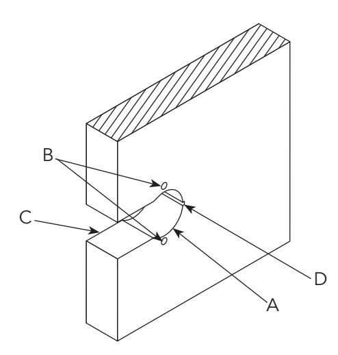
Important: The accuracy of the door preparation is critical for the proper functioning and security of this lever handle lock. Misalignment can cause premature wear and tear and a lessening of security.

WARNING
This product can expose you to lead which is known to the state of California to cause cancer and birth defects or other reproductive harm. For more information go to www.P65warnings.ca.gov.

WARNING
80-9260-0007-010 10/23 Attention Installer: Any retrofit or other field modification to a fire rated opening can potentially impact the fire rating of the opening, and Assa Abloy makes no representations or warranties concerning what such impact may be in any specific situation. When retrofitting any portion of an existing fire-rated opening, or specifying and installing a new fire-rated opening, please consult with a code specialist or local code official (Authority Having Jurisdiction) to ensure compliance with all applicable codes and ratings.
1-800-235-7482 • www.assaabloy.com
2. Install Lock
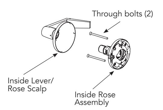
a. Disassembly
Remove inside lever/rose scalp, through bolts and rose assembly to disassemble.
b. Install Lockbody/Latch Outside Assembly
Fit lockbody/latch assembly in door, aligning latch bevel with door swing. If required, latch may be reversed.
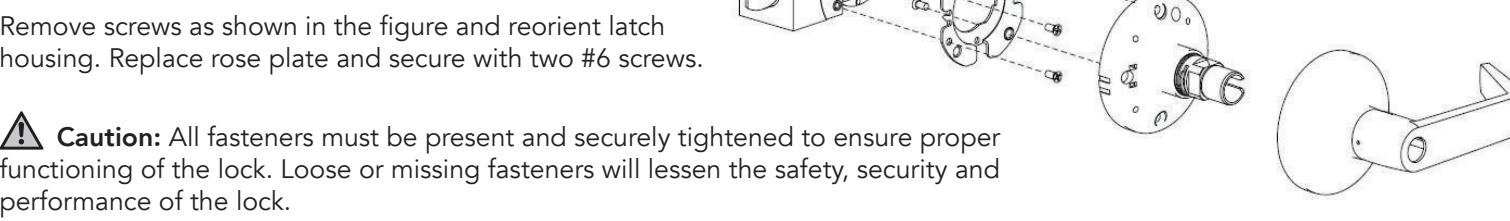
To reverse latch:
housing. Replace rose plate and secure with two #6 screws.
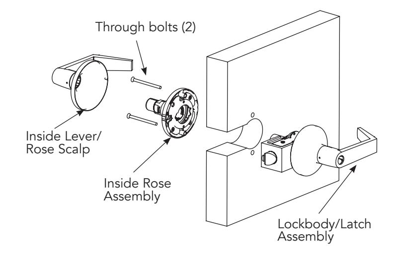
c. Install Inside Components
1. Slide inside rose assembly onto lockbody. See figure.
Note: The grove must line up with the drive lug on the spindle. Fasten rose assembly with two through bolts.
- 2. Place rose scalp on rose assembly.
- 3. Install lever by snapping into place. Pull to ensure it is properly seated.
80-9260-0007-010 10/23